In multi-hop communication systems, two-way relaying is one of the solutions to mitigate the spectral efficiency loss caused by a half-duplex transmission. In this paper, a simple two-way relaying scheme is proposed for two-hop two-user multiple input multiple output (MIMO) systems. In the proposed system, a base station and a relay station (RS), both equipped with two antennas, form a point-to-point MIMO channel, while the RS and two single-antenna mobile users form a point-to-multipoint multiuser (MU)-MIMO channel. Numerical examples show that the proposed system achieves a significant sum rate gain as compared to a one-way relaying system as the distance between a relay and the two users decreases. We also show that although we can expand the proposed scheme to more than two users, its performance gain as compared to that of one-way relaying decreases with an increase in the number of users.
Next-generation wireless communication systems will demand enhanced link capacity and larger coverage. One of the solutions to meet these demands is to use space-division multiple access in a multiuser multiple input multiple output (MU-MIMO) system, which can achieve a multiplexing gain even when each user has a small number of antennas [1-3]. However, the problem arises when the users are far away from the base station (BS) and there are many obstructions between the BS and the users, such as in an urban cell edge area, where the users experience significant path loss and shadowing. The conventional solution to overcome this coverage shrinking problem is to increase the density of the BS or the repeater. Unfortunately, additional BS deployment is impractical due to its considerably high cost. Moreover, the repeater has the problem of amplifying interference and finds it difficult to perform complicated signal processing.
One of the practical schemes to enhance the coverage area in a cellular network is fixed relay station (RS)-based multi-hop communication [4, 5]. In this system, the BS and the RS form a point-to-point MIMO channel, while the RS and the users form a point-to-multipoint MU-MIMO channel. Deploying the RS with multiple antennas in a cell edge area, where the nearby users experience significant shadowing, enables the system to achieve a high data transmission rate at the BS and the users [6]. In addition, since the fixed RS can perform more complex operations than a mobile relay, the RS can take over a portion of the operations in the BS [7]. Thus, it is possible to reduce the complexity of the BS by using the RS as a sub-BS. However, the problem of a relay system is that all the terminals in this system operate in the half-duplex mode; this leads to a loss in the spectral efficiency [8]. Conventional techniques to solve this problem include opportunistic relaying, two-path relaying, and two-way/bi-directional relaying [8-17]. Among them, in this study, we consider a two-way relaying system where a relay simultaneously transmits the uplink data symbols to the BS and the downlink data symbols to the users [10-15].
The coded two-way relaying schemes have been shown in [10, 11] by using bit-wise and symbol-wise XOR operations at the RS, respectively. A combination of two-way relaying and cooperative relaying has been proposed in [12]. In [13, 14], an information-theoretic approach for various two-hop two-way relaying schemes has been introduced by showing that the sum rate can be increased significantly as compared to the one-way relaying scheme. In [15], the two-hop two-way relaying-based MU-MIMO system has been proposed, where the decode-and-forward operation is performed at the RS, while the successive interference cancelation is performed by the BS and the users. However, the author in [15] did not describe the transmitting signal construction at the RS in detail. In addition, the feedback load and the computational complexity of the proposed scheme in [15] are very high.
In this paper, we propose a low-feedback-load and lowcomplexity two-way relaying scheme for a two-hop two-user MIMO system. In the proposed scheme, one needs three phases to transmit the uplink and downlink data symbols and the operation of the first two phases is the same as in [15]. In the third time slot, the RS decodes the received signal and constructs the transmitting signal by using singular value decomposition (SVD) and QR decomposition and simultaneously transmits this signal to the BS and the users. We also propose an optimal power allocation algorithm at the RS for the uplink and downlink data symbols.
The rest of this paper is organized as follows: Section II introduces the system model and notations, and Section III describes the process of the proposed scheme, computes its sum rate, and proposes an optimal power allocation. Section IV shows the simulation results of the proposed scheme in comparison with the conventional schemes. Finally, Section V presents the conclusion.
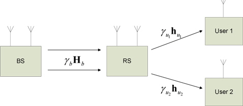
The considered two-hop two-user MIMO system is as illustrated in Fig. 1. There are only two users in this system, and the direct path between the BS and both the users is blocked due to the path loss and shadowing. Also, the time division duplex (TDD) mode is assumed, where the channels are assumed to be constant during one TDD frame but change independently between different frames. Both the BS and the RS are assumed to have two antennas, and each user has a single antenna. The matrix
In the proposed scheme in [15], a TDD frame is equally divided into three time slots. In the first and the second time slots, the BS transmits two data symbols to the RS by using the space time block code [18]. At the same time, user 1 and user 2 transmit the uplink data symbols to the RS in the first and the second time slots, respectively. While one of the two users, say user 1, transmits the uplink data symbol, the other user listens to the transmission of user 1. Then, the received signal vector at the RS in the
and
The noise terms, (
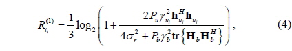
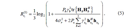
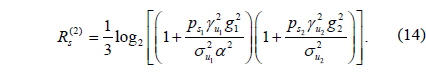
After the transmissions of the first and the second time slots, the RS decodes the downlink and uplink data symbols by using minimum mean square estimation and successive interference cancelation (MMSE-SIC) [19] depending on the two decoding ordering methods. For example, at first, the RS decodes the uplink data symbols by treating the downlink data symbols as interference and subtracts the uplink data symbols from the received signal vector and then, decodes the downlink data symbols without interference. In this case, the achievable sum rates of the downlink and uplink transmission, and , are given as [20]
and
where tr {·} denotes the trace operator.
Similarly, if the RS first decodes the downlink data symbols and then, decodes the uplink data symbols, and are given as
and
In the third time slot, the RS executes the water-filling algorithm [20] to transform uplink data symbols and the dirty paper code (DPC) [21] into the downlink data symbols, which are denoted as b
Note that the BS and the users need to know the perfect channel state information (CSI) of the other side to cancel the interference, which leads to a high feedback load. In addition, although executing the DPC at the RS achieves the optimal sum rate for the MIMO broadcast channel, it may be difficult to implement this in the practical system and its complexity may be very high.
>
B. Proposed Two-Way Relaying Strategy
For the first two time slots, the operation of the proposed scheme is the same as that in [15]. Let
The application of the SVD to the channel matrices H
where U, V , and Q are the unitary matrices, Σ has nonzero diagonal elements placed in the descending order (λ1 > λ2 > 0), and is the lower triangular matrix whose diagonal terms,
Let and where
where D(
However, if
At the BS, the received signal is multiplied by the unitary matrix V
where n
where n
Before transmission, the RS feeds back the information of the correlation matrix U
Using this feedback information, the BS and the users execute the SIC to obtain r
and
Note that the feedback load of the proposed protocol is considerably lower than that obtained in the previous work. Perfect channel knowledge of the other path H
The results of the electromagnetic simulations for the lumped element and the distributed design show that the attenuation characteristics of the lumped design are superior to those of the distributed one.
>
C. Sum Rate of the Proposed Scheme
After transmission of the third time slot, the sum rate of the uplink data symbols at the BS can be computed from (11), as follows:
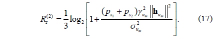
In addition, the sum rate of the downlink data symbols at the both users can be computed from (12), as follows:
However, since additional power is used for presubtraction as in (8), there may be a situation in which the rate of the downlink data symbol is higher than the sum rate of the downlink data symbols of both users when the RS only transmits the downlink data symbol of the user with the largest channel gain . This situation occurs when the correlation of the two uplink channel vectors, i.e., is high, and thus,
Therefore, we need check whether
Then, the corresponding sum rate of the downlink data symbol can be calculated as
Consequently, the total system sum rate can be achieved in a TDD frame as
>
D. Optimal Power Allocation at RS
In this paper, only the power allocation (PA) at the RS is considered since the BS and the users need to know the perfect CSI of two channel matrices, H
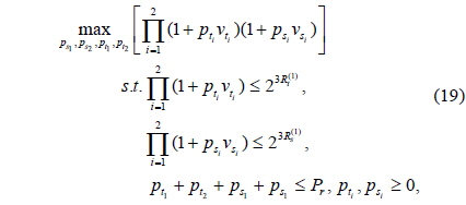
Based on the sum rate of the downlink and uplink data symbols and , which is achieved by using a certain decoding order, the optimal PA for
where , and This optimization problem can be solved by the following algorithm:
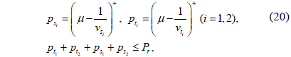
• Step 1: Using the water-filling algorithm, solve the sum rate optimization problem in (19) by considering only the power constraints as
where
• Step 2: Since the power of the RS is enough to meet the sum rate of the downlink and the uplink data symbols at the RS, and , respectively, find the optimal PA by solving the following problem:
where
Then, the algorithm is completed.
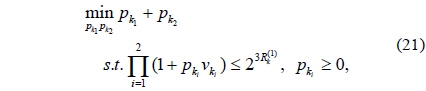
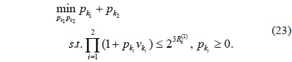
• Step 3: Let
The solution can be found as
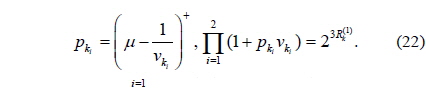
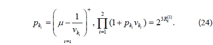
Then, solve the following problem to calculate and , where
The solution of (25) can be found as
Then, the algorithm is completed.
On the other hand, the optimal PA for
where . This optimization problem can be solved by the similar processing for the proposed algorithm.
It should also be noted that the RS determines the decoding order to maximize the total sum rate if the RS can estimate the channels perfectly. For this reason, the RS needs to execute the power loading algorithm twice since there are two decoding ordering methods.
In this section, various Monte-Carlo simulation results are illustrated by averaging more than 10,000 channel realizations. It is assumed that the noise variances are the distance between the BS and the users, d, is kept constant as 2 km; the distance between the RS and each user is
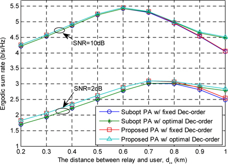
Fig. 2 shows the ergodic sum rate of the proposed scheme calculated on the basis of the optimal PA for a low and a high signal-to-noise ratio (SNR). To show the optimality of the proposed PA, the sub-optimal PA is illustrated, which achieves a near-optimal sum rate at a high SNR. In the suboptimal PA, at first, the lower bound of the cost function
Then, the following optimization problem is solved by geometrical programming.
Fig. 2 shows that the proposed PA achieves the optimal sum rate of the system since sub-optimal PA achieves the optimal sum rate as SNR reaches infinity. Note that the gap between the two PA schemes at a low SNR is caused by the lower bound optimization of sub-optimal PA. Besides, Fig. 2 shows that fixing the decoding order to decode the uplink data symbol at the first time and the downlink data symbol at the next time can provide the near-optimal sum rate as the distance between the RS and the user decreases.
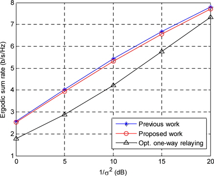
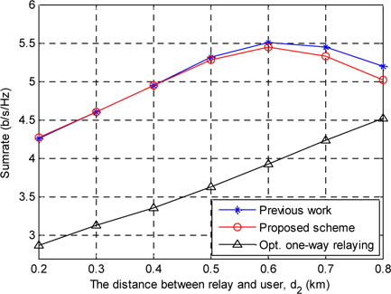
In Figs. 3 and 4, the proposed scheme is compared to the previous work presented in [15] and the optimal one-way relaying scheme in order to demonstrate the performance gain of the proposed scheme. In the optimal one-way relaying scheme, a TDD frame is equally divided into four time slots. In the first and the second time slots, the BS transmits the downlink data symbols to the RS, and the users transmit the uplink data symbols to the RS. The RS decodes the downlink and uplink data symbols by using MMSE-SIC. In the third time slot, the RS transmits the decoded uplink data symbol to the BS by using the waterfilling algorithm. Finally, the RS transmits the decoded downlink data symbol to the users by using DPC in the fourth time slot. It is assumed that the optimal PA is performed at the RS for all the schemes.
Fig. 3 illustrates the sum rates versus of the three different schemes for 1 /
This is because as
Two-way communication at the RS is one of the solutions to overcome the disadvantage of the time resource consumption due to the half-duplex constraint. A problem of this scheme is the degradation of the system sum rate mainly due to the interference. In the proposed scheme, the RS constructs the transmitting signal vector by employing SVD and QR decomposition, where the feedback load at the BS and the users is considerably lower than that in the previous work described in [15]. Simulation results show that the proposed protocol can achieve a significant sum rate gain as compared to the one-way relaying scheme. In addition, the DPC used in [15] has some difficulties for practical implementation. In this aspect, the proposed scheme can be easily implemented in various circumstances. Although we can expand the proposed scheme to more than two users, its performance gain as compared to one-way relaying decreases with an increase in the number of users. This is because each user needs one time slot for transmitting the uplink data symbol to the RS and the power consumption of the interference pre-subtraction for the downlink transmitting signal at the RS increases with an increase in the number of user.