A novel design of a simple circular ring with open-ended monopole antenna for wireless local area network (WLAN) applications is proposed in this article. The proposed antenna consists of an open-ended circular ring and 50-Ω microstrip feed-line. The proposed antenna is capable of generating two separate resonant modes with good impedance-matching conditions. A prototype of the proposed antenna is designed, fabricated, and measured. Acceptable agreement between the measurement and simulation results is achieved. Experimental results show that the proposed antenna has operating bandwidths of 1.99–3.04 GHz and 5.08–6.1 GHz with a return loss of less than -10 dB, covering the required bandwidths of the 2.4/5.2/5.8-GHz WLAN standards. This is a microstrip antenna for IEEE 802.11a/b wireless local area networks applications. Meanwhile, the two-dimensional (2D) radiation patterns and three-dimensional (3D) gain performance of the antenna are also observed and discussed.
The rapid advances in the wireless communication industry demand novel designs that can be used in more than one frequency band and that will allow size reduction. Wireless local area networks (WLANs), wireless printers, and the PCMCIA (Personal Computer Memory Card International Association) card, for instance, utilize the 2.4- GHz band. Moreover, major advances have recently been made in WLAN communications, and to meet the IEEE 802.11a, HiperLAN, and 802.11b WLAN standards, many related products have been designed in such a way as to make them capable of dual-band operations in the 2.4 GHz (2.4–2.484 GHz) and the 5.2/5.8 GHz (5.15–5.95 GHz) bands.
A demand for dual-band antennas has thus emerged, and consequently, a number of experimental and theoretical studies have been conducted on multiband antennas. With an increase in the popularity of WLAN communication, the demand for a printed monopole antenna designed with a low-profile, light-weight, flush-mounted, and simple structure has increased. Recently, multiband antennas for WLAN applications have been reported [1-11]. Among all these antennas, printed monopole antennas play an important role due to their attractive features of simple structure, low profile, and reasonably good performance. In particular, several studies on the circular ring monopole antenna have been conducted [12-18].
The circular ring, printed monopole antenna [12], and the M-shaped antenna surrounded with a ring monopole [13] for wideband operations have been developed. Further, the band-notched circular ring monopole antenna [14-16], the coplanar waveguide (CPW) dual ring loop antenna for dualband operation [17], and a ring monopole ultra-wideband (UWB) antenna with band-notched [18] have been proposed.
In this study, a novel circular ring with an open-ended monopole antenna with a strip suited for dual-band WLAN applications was designed. The proposed antenna comprises a circular ring with an open-ended monopole antenna. By appropriately selecting the dimensions of the proposed antenna, we can achieve good dual broadband bandwidth and radiation characteristics suitable for WLAN 2.4/5.2/5.8- GHz operations. The detailed design considerations and experimental results of the proposed monopole antenna for WLAN operation are presented and discussed below.
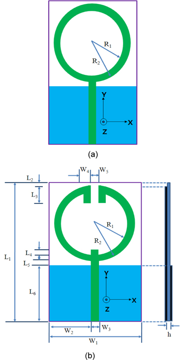
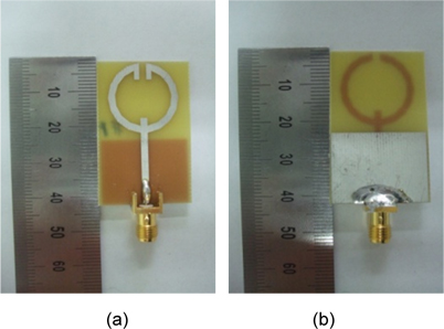
Fig. 1 shows the geometry of the proposed WLAN monopole antenna to achieve a dual-band frequency operation. Fig. 1(a) shows the geometry of the conventional circular ring antenna and Fig. 1(b) shows the proposed circular ring open-ended monopole antenna for WLAN applications. In this design, the total size of the substrate was 21.0 mm × 45.0 mm (
>
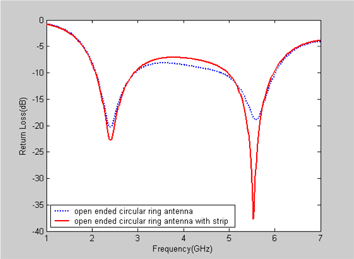
A. Effect of the Open-Ended Circular Ring
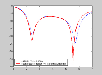
Fig. 2 shows the return loss of a conventional circular ring and the open end of the circular ring. In the 2.4- and 5-GHz bands, as can be seen in the figure, the impedance bandwidth and return loss characteristics varied slightly. It can be seen in the figure, however, that in the case of the open-ended circular ring antenna with a strip, the return loss characteristics were better than those in the case of the conventional circular ring antenna. Thus, to design an optimal dual-band WLAN operation, we introduce an openended circular ring antenna with a strip.
>
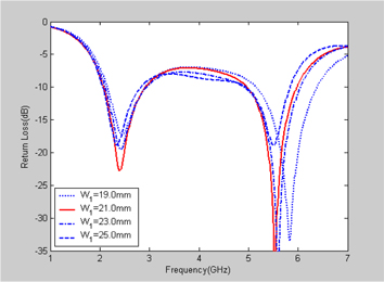
B. Effect of the Ground Plane
Fig. 3 shows the return loss for different values of the ground plane (
>
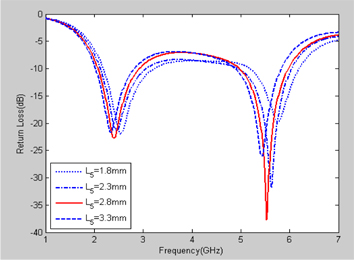
C. Effect of the Gap between the Ground Plane and the Circular Ring Open-Ended Antenna, L5
Fig. 4 shows the return loss for different gaps (
>
D. Effect of the Strip in the Open-Ended Circular Ring
A strip was introduced into the open-ended circular ring to alter the input impedance characteristics. Fig. 5 shows the return loss with and without a strip in the open-ended circular ring. The impedance bandwidth and return loss characteristics worsened when there was no strip in the open-ended circular ring. This indicates that the strip plays an important role in the impedance matching of the proposed antenna. The optimal values of the strip width (
The proposed antenna structure has several design parameters that can handle the resistance and the reactance of the antenna input impedance. As such, the dimensions of the proposed antenna were set as follows:
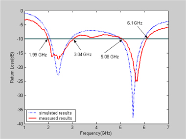
A prototype of the optimized antennas was fabricated and measured for the return loss, radiation pattern, and gain. Fig. 7 shows the measured and simulated return loss of the proposed antenna for a multioperation wireless communication application. The frequency response of the return loss of the proposed antenna was measured using an Anritsu MS4644A vector network analyzer at Silla University. The results demonstrate that simulated data and measured data have a generally acceptable agreement. It can be seen in the figure that there is a slight difference between the simulation and the measurement results. This is probably due to the influence of the cable connected to the fabricated antenna in the measurement procedure. Further, this discrepancy between the measurement data and the simulation results could be due to the effect of the SMA port. To confirm the accurate return loss characteristics of the designed antenna, it is recommended that the manufacturing and measurement process be performed carefully. There are two resonant modes that are excited at approximately 2.425 and 5.665 GHz, respectively, with wide impedance band-widths. The lowest resonant mode has a 10-dB impedance bandwidth of 1,050 MHz (1.99–3.04 GHz), which covers the 2.4-GHz WLAN bands. The second resonant mode has an impedance bandwidth of 1,020 MHz (5.08–6.1 GHz), which satisfies the required bandwidth of the 5.2/5.8-GHz WLAN bands. Clearly, the design prototype of the proposed antenna has sufficient bandwidth to cover the needs of the 2.4- and 5- GHz WLAN bands (2.4–2.484 GHz and 5.15–5.825 GHz, respectively).
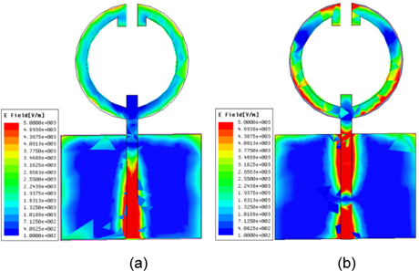
Theoretically, HFSS was used to evaluate and verify the two resonant frequencies of 2.42 and 5.63 GHz, which mainly depended on the lengths of the open-ended circular ring. Fig. 8(a) and (b) show the surface current density excitations along the open-ended circular ring antenna in the cases of the two resonant frequencies of 2.42 and 5.63 GHz, respectively. As shown in Fig. 8(a), the 2.4-GHz band surface current density excitations along the open-ended circular ring was observed when the resonant frequency was 2.42 GHz. Thus, it is implied that the excitation of the 2.4- GHz bands is mainly contributed by the open-ended circular ring. As shown in Fig. 8(b), however, larger surface current density excitations flowed along the bottom of the openended circular ring antenna when the resonant frequency was 5.575 GHz. As we can see in this figure, the 5-GHz band is more strongly excited than the 2.4-GHz band in the case of the open-ended circular ring antenna.
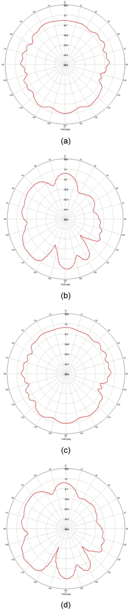
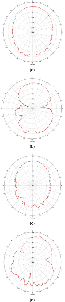
Fig. 9 shows the measured 2D far-field radiation patterns in the E-plane (x-z plane) and the H-plane (y-z plane) at the 2.4- and 2.45-GHz bands. Fig. 10 shows the measured 2D far-field radiation patterns in the E-plane (x-z plane) and the H-plane (y-z plane) at the 5.3- and 5.7-GHz bands. From the perspective of these radiation patterns, the proposed antenna displays omni-directional radiation characteristics in the Hplane and monopole-like radiation pattern characteristics in the E-plane at the considered frequencies.
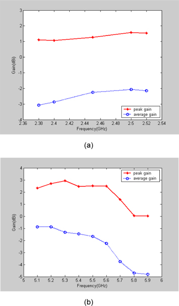
Fig. 11(a) and (b) show the 3D measured antenna peak and the average gain for the frequencies across the 2.4- and 5-GHz bands. The 2.4-GHz band had an antenna peak gain level of approximately 1.07 to 1.58 dBi in Fig. 11(a), and the 5-GHz band, approximately 0.02 to 2.93 dBi in Fig. 11(b).
The 2.4-GHz band had an antenna average gain level of approximately -3.07 to -2.06 dBi in Fig. 11(a), and the 5- GHz band, approximately -4.8 to -0.87 dBi in Fig. 11(b). The 2D antenna gain had a peak value of 1.58 dBi at 2.5 GHz. At 5.3 GHz, the 2D maximum peak gain was 2.93 dBi and at 5.6 GHz, 2.48 dBi. As a result, the gain of the proposed antenna within the operating bands satisfies the requirements for WLAN systems
In this article, we proposed a simple circular ring openended monopole antenna for dual-band WLAN operations. With the use of the open-ended circular ring, the impedance bandwidth needed to meet the requirements of WLAN in the 2.4/5.2/5.8-GHz bands was achieved. Various parameters of the proposed antenna were optimized via simulation (HFSS) and tested. Parametric studies of the proposed antenna were conducted and the mechanisms of the dual-band operation were discussed. This proposed monopole antenna had -10 dB impedance bandwidths of approximately 1,020 and 1,050 MHz (1.99–3.04 and 5.08–6.1 GHz) or approximately 10.44% and 18.25%. The experiment results showed that good impedance matching was achieved. Omni-directional radiation pattern characteristics for frequencies over the WLAN bands were also obtained for the proposed antenna. The proposed antenna’s measured peak gain varied between 1.07 and 1.58 dBi in the case of the 2.4-GHz band and 0.02 and 2.93 dBi in the case of the 5-GHz band. Because of its low cost, light weight, and compact size, the proposed antenna is very suitable for WLAN applications.