This paper presents a modified TEM horn that improves radiation characteristics at a low frequency region. The proposed antenna consists of an asymmetric TEM (ATEM) horn and a loop structure with an elliptical shape. The bandwidth and gain at low frequency region can be enhanced by using the ATEM horn configuration and adding a loop structure with an elliptical shape to the ATEM horn. The bandwidth of the proposed antenna is from 2.14 to over 20 GHz, whereas that of the conventional TEM horn is from 2.7 to over 20 GHz, where the dimensions of both antennas are the same except for the thickness of the loop structure. The physical and electrical dimensions of the proposed antenna are 60 mm × 62.5 mm × 64 mm (width × height × length) and 0.428 λL × 0.445 λL × 0.456 λL, where λL corresponds to the lowest frequency of the bandwidth. The realized gain of the proposed antenna is improved by 0.802 dB on average at the low frequency region (2 to 8 GHz), where the maximum gain increase is 2.932 dB when compared to a conventional TEM horn.
Ultrawideband (UWB) antennas have been researched widely for many years due to increased demands in communication, electromagnetic compatibility (EMC) measurement, and radar systems [1,2]. Among various UWB antennas, the TEM horn is widely used due to its merits of wide bandwidth, low dispersion, directive radiation pattern, and ease of construction [1]. However, a conventional TEM horn has relatively larger dimensions compared to other UWB antennas [3]. The size of TEM horns can be reduced by applying a loading resistance and resistive sheet to reduce the reflections at the end of the apertures [4]. These types of antennas can achieve electrically small sizes due to the enhanced reflection characteristics; however, the radiation efficiencies degrade because of the resistive materials. In [5], a TEM horn with a square loop structure is introduced. The presented antenna also has improved bandwidth when compared to the conventional TEM horn because of the reduced reflection at the end of the aperture. In addition, the gains at the low frequency region are enhanced by routing currents behind the horn. The associated magnetic dipole moment can be oriented to combine with the electric dipole moment to orient the low frequency radiation in the forward direction [5]. However, even though the antenna has improved gains when compared to a conventional TEM horn at the low frequency region, the low frequency gains are still small, which has a negative effect on the gain flatness of the realized gain property.
In this paper, we propose a modified TEM horn that realizes wide bandwidth and improved gain at the low frequency region. The proposed antenna consists of an asymmetric TEM (ATEM) horn and a loop structure with an elliptical shape.
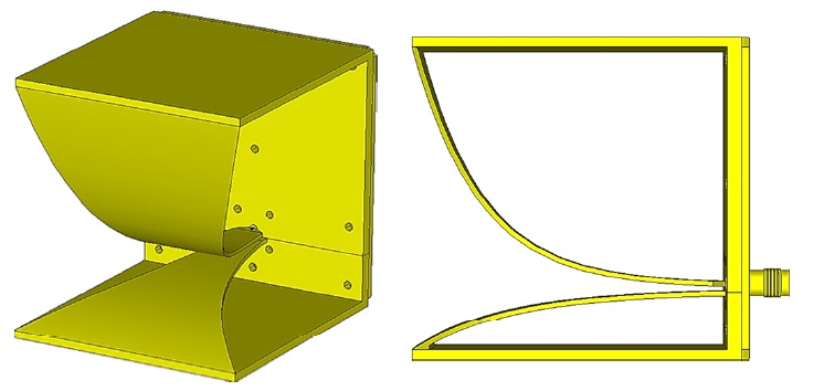
An asymmetric configuration can improve a bandwidth of the antenna by extending the length of the effective electric field on the aperture [6]. Fig. 1 shows the symmetric and the asymmetric TEM horns, where both antennas have the same dimension of 60 mm × 60 mm × 60 mm (width × height × length). The
2. ATEM Horn with Loop Structure
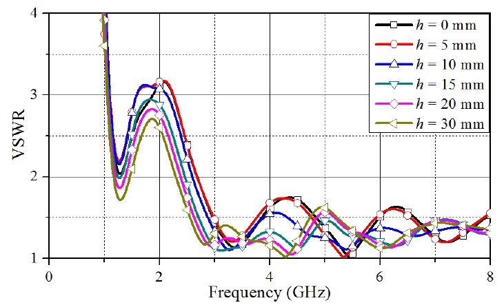
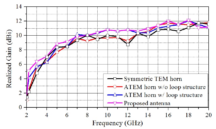
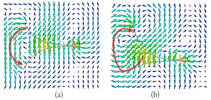
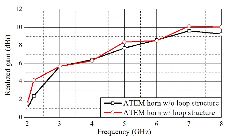
We enhance the realized gains of the ATEM horn at low frequency region by applying a loop structure to the ATEM horn, as shown in Fig. 4. The dimension of the antenna is 60 mm × 62.5 mm × 64 mm, where the dimension difference with the ATEM horn is due to the thickness of the added loop structure. The realized gain of the ATEM horn can be enhanced by combining the associated magnetic dipole moment and the electric dipole moment, which leads the low frequency radiation in the forward direction [5]. Fig. 5 depicts the simulated results of the realized gains of the ATEM horns according to the existence of the loop structure. Adding the loop structure improves the average gain by 0.5 dB, where the maximum increased gain is 1.75 dB at 2.2 GHz. It verifies that the realized gains at a low frequency region can be enhanced by adding the loop structure to the ATEM horn.
3. ATEM Horn with Modified Loop Structure
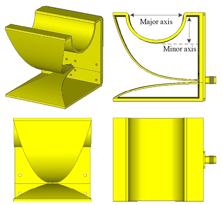
Even though the ATEM horn with the loop structure realizes improved low frequency gain, the gain is still low, which has a negative effect on the gain flatness. We enhance the low frequency gains of the ATEM horn with loop structure by inserting an elliptical shape into the loop structure, as shown Fig. 6. The inserted shape in the loop structure provides additional design parameters that may be tailored in order to control the antenna radiation pattern [7]. The elliptical shape has an optimum configuration for realizing the highest gain at the boresight of the antenna because the shape affects the main beam direction. The values of the major and the minor axis are selected as 43.5 and 29.5 mm, respectively, to realize the highest gain at the boresight of the antenna. The dimension of the proposed antenna is the same as that with the ATEM horn with the loop structure (60 mm × 62.5 mm × 64 mm).
Fig. 7 shows the simulated VSWR results of the proposed antenna. The bandwidth of the antenna is from 2.14 to over 20 GHz, which verifies that the antenna with a loop structure has extended bandwidth toward the low frequency region when compared to an antenna without a loop structure. Fig. 8 illustrates the simulated realized gains of the symmetric TEM horn, the ATEM horn, the ATEM horn with loop structure, and proposed antenna. It shows that the proposed antenna has improved gain at the low frequency region (2 to 8 GHz). The average gain is improved by 0.802 dB, where the maximum increased gain is 2.932 dB at 2.2 GHz when compared to a symmetric TEM horn.
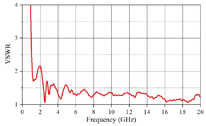
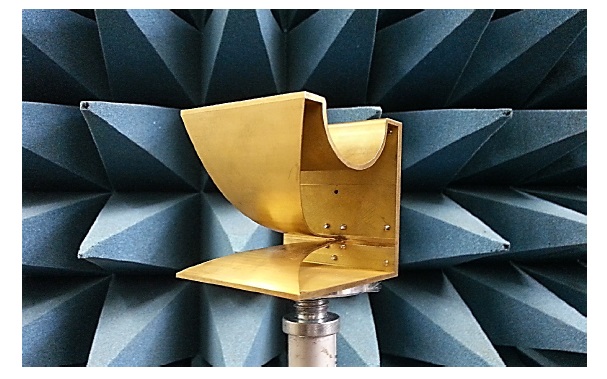
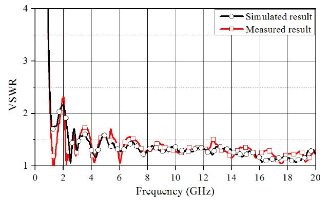
Fig. 9 shows the configuration of the fabricated antenna. The antenna is made of brass and its bandwidth is from 2.14 to over 20 GHz for VSWR < 2, as shown in Fig. 10. It shows that the measured VSWR result is well matched to the simulated results across the whole frequency range.
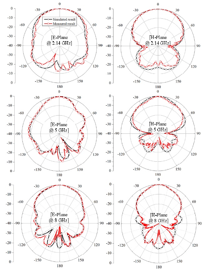
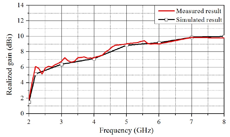
Fig. 11 depicts the measured radiation patterns on the E-and H-planes at 2.14, 5, and 8 GHz and Fig. 12 shows the measured realized gain at the boresight in the low frequency region (2 to 8 GHz). The simulated and measured results are well matched. The realized gains at higher frequencies are not determined due to the limitations of the measurement environment.
This paper presents a modified TEM horn for enhanced radiation characteristics at the low frequency region. The bandwidth of the conventional symmetric TEM horn is improved by applying an ATEM horn. In addition, to enhance the realized gain at low frequency region, a loop structure with an elliptical shape is added to the ATEM horn. The bandwidth of the proposed antenna is extended by 26% toward the low frequency region and the realized gain is improved by 0.802 dB, on average, where maximum increased gain is 2.932 dB at the low frequency region when compared to the conventional TEM horn.