검색 전체 메뉴
PDF
맨 위로
OA 학술지
Multiband-Notched UWB Antenna Using Folded Slots in the Feeding Structure
  • 비영리 CC BY-NC
  • 비영리 CC BY-NC
ABSTRACT
Multiband-Notched UWB Antenna Using Folded Slots in the Feeding Structure
KEYWORD
Bandstop Filter , Folded Slot , Printed Circular Monopole , Ultra-Wideband
  • Ⅰ. INTRODUCTION

    The Federal Communication Commission of the United States of America approved the utilization of the 3.1-10.6 GHz unlicensed band for commercial ultra-wideband (UWB) communication in 2002 [1]. Since then, many types of antennas have been developed for UWB applications [2-5]. Nevertheless, the UWB antennas face many challenges, including establishment of wideband impedance matching, radiation stability, compact size, and low manufacturing cost. Furthermore, owing to the overlap of the UWB band and extant narrow band applications, such as the worldwide interoperability for microwave access application (WiMAX: 3.3-3.7 GHz) band, the wireless local area network (WLAN: 5.15-5.825 GHz) band, and the International Telecommunication Union (ITU: 7.725-8.275 GHz) band, UWB antennas with the notched-band characteristic must avoid interference. A variety of methods have been presented to achieve the band notch characteristic in which a pair of slots is etched onto a radiating patch of a monopole antenna to provide good rejection in the 5-GHz WLAN band [6]. A CPW-fed monopole antenna [7] was presented with a slotted/added rectangle on the opposite side of the substrate to provide a band-notched function. Split ring resonators were etched onto the radiating patch of a UWB antenna for the band notches [8,9]. In most of these designs, notch functions were achieved by implementing slots on the radiating elements or ground plane of the antenna. However, this technique cannot be applied to antennas that lack a large area for implementing the slots, such as log-periodic, spiral, or Vivaldi antennas. Recently, other methods, such as utilizing the electromagnetic band-gap structures [10], asymmetric coupled-lines [11], and capacitively loaded loop resonators [12] have been employed in the feeding structure of the UWB antenna to obtain notched bands at the desired frequency. However, these techniques introduce an additional complexity of the feeding configuration.

    This paper describes a multiband-notched UWB antenna with a simple primary radiating element of a printed circular monopole. The multiband notch characteristic is completely engineered in the feeding structure by using multiple bandstop filters, which consist of three folded-slots: one slot is etched onto the ground plane, and other two are etched onto the microstrip line. The slots are distinctly assigned for notches at the 3.5-GHz WiMAX, 5-GHz WLAN, and 8-GHz ITU bands. An ANSYS-Ansoft high-frequency structure simulator (HFSS) was used for simulations throughout this work.

    Ⅱ. ANALYSIS OF BANDSTOP FILTERS WITH A FOLDED SLOT

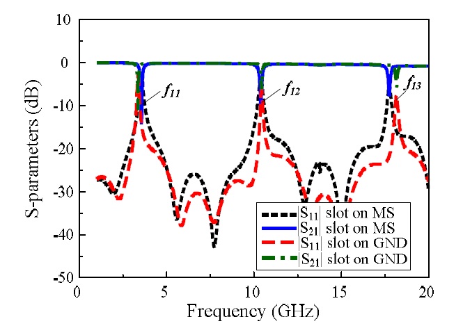
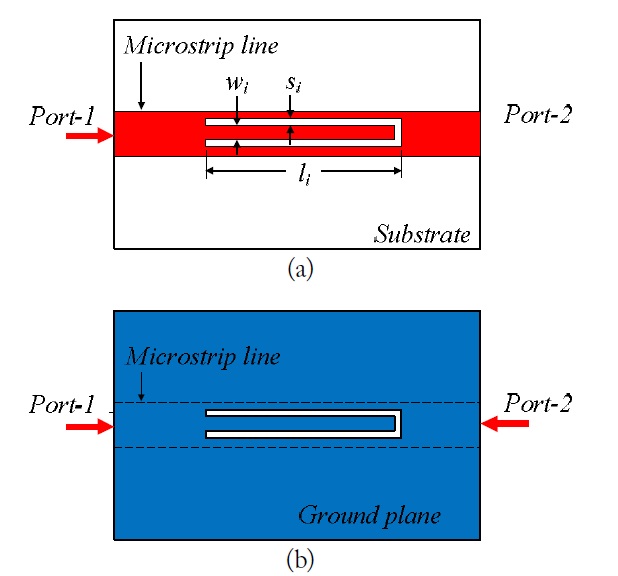
    Fig. 1(a) and (b) show the geometries of the bandstop filter with a folded-slot on the microstrip line and the ground plane. The microstrip line was designed on an RT/Duroid 5880 substrate (
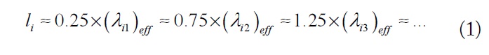
εr = 2.2, tan δ = 0.009, and h = 0.7874 mm) with a characteristic impedance of 50-Ω. The filter was modeled as a transmission line with the port-1 at the input and the port-2 at the output, as shown in Fig. 1. Both designs with the folded slot on the microstrip line or ground plane exhibited bandstop characteristics, which are controlled by the slot shape. The slot length (li) mainly determines the resonance frequency, while the spacing between slots (wi) and gap size (si) mainly determines the bandwidth, as reported in [13]. Extending the frequency range of interest, we observed that these designs yielded several stopbands, which are periodic, as shown in Fig. 2. The slot lengths needed to achieve the stopbands at the desired frequency can be given by

    image

    Here, i1)eff, i2)eff, and i3)eff are the effective wavelengths at the first, second, and third stopbands, respectively. Fig. 2 also shows a comparison of transmission and reflection characteristics between the filter with folded-slot etched on the ground plane and the microstrip line. Their stop-bands were slightly different, but their periods are almost the same. These results indicate that the filter with a folded slot on the ground plane or the microstrip line has multiple stop-bands. The folded slots are employed in the feeding structure of UWB antenna in order to create notch bands at the desired frequency.

    Ⅲ. MULTIBAND-NOTCHED UWB ANTENNA DESIGN AND CHARACTERISTICS

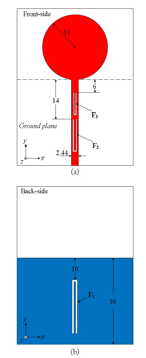
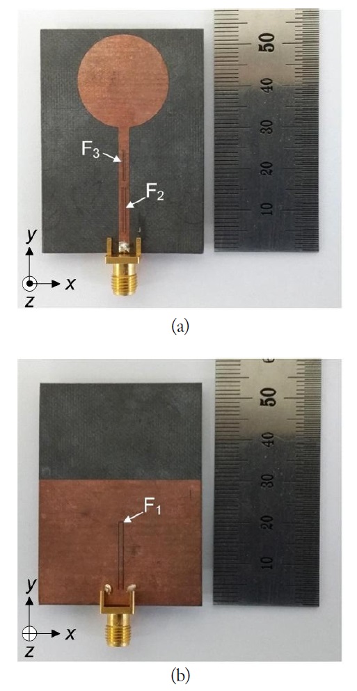
    Fig. 3 shows the geometry of the multiband-notched UWB antenna. The antenna was realized with a simple circular monopole built on a 54 × 40-mm RT/Duroid 5880 substrate (εr = 2.2, tan δ = 0.009, and h = 0.7874 mm) and fed by a 50-Ω microstrip line. The multiband-notched characteristic was obtained by inserting three folded slots (F1 is etched on the ground plane, whereas F2 and F3 are etched on the microstrip line), described in the previous section, into the feeding structure of the antenna. The first stopbands generated by the F1, F2, and F3 slots were distinctly assigned for notches at the 3.5-GHz WiMAX, 5-GHz WLAN, and 8-GHz ITU bands, respectively. The optimized design parameters for the three folded slots are given in Table 1.

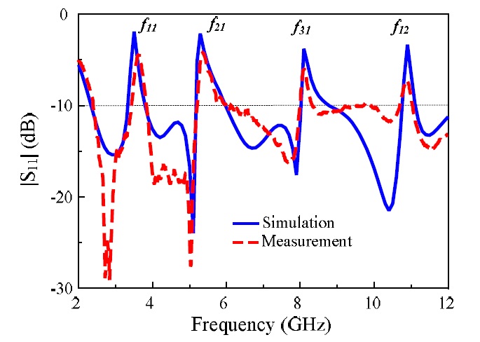
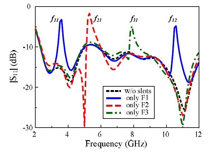
    The individual roles of each slot embedded in the feeding structure of the UWB antenna, and their simulated |S11|, are illustrated in Fig. 4. Without slots, the UWB antenna has |S11| < -10 dB from 2.4 GHz to 12 GHz, and no notched band exists. Two notches are present at 3.5 and 10.9 GHz with only the F1-slot, a notch at 5.3 GHz with only the F2-slot, and a notch at 8.1 GHz with only the F3-slot. The proposed antenna employs all three slots in the feeding structure for the multiband-notch.

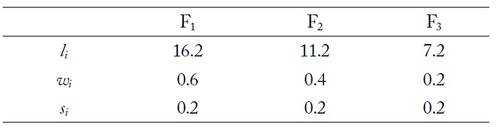
    [Table 1.] Optimized design parameters of folded-slots for multiple stopbands (unit in mm)

    label

    Optimized design parameters of folded-slots for multiple stopbands (unit in mm)

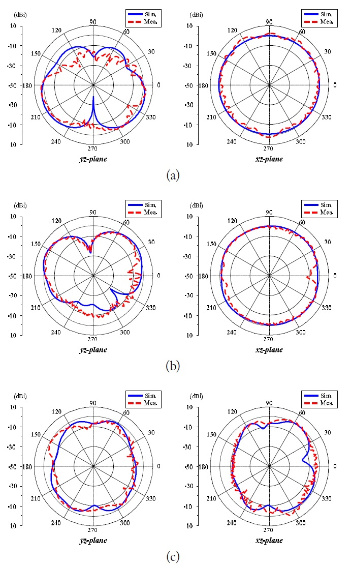
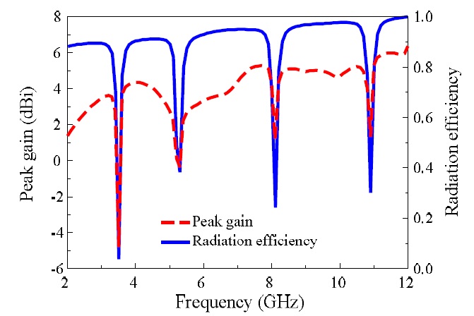
    This multiband-notched UWB antenna was fabricated and measured for performance verification. The antenna was built on both sides of an RT/Duroid 5880 substrate with a copper thickness of 17 μm. A 50-Ohm SMA connector was used as a microstrip-to-coaxial line transition (not included in the simulation) in the fabricated sample. A photograph of the fabricated antenna is shown in Fig. 5. A comparison between the simulated and measured |S11| of the UWB antenna is shown in Fig. 6. Agreement between the simulation and the measurement is observed. Both results yielded impedance matching bandwidth covering the UWB band (3.1-10.6 GHz) for |S11| < -10 dB and three notched bands at 3.5-GHz WiMAX, 5-GHz WLAN, and 8-GHz ITU. Additionally, the higher notched band appeared at 10.9 GHz, which is the second stopband of the F1 slot. Fig. 7 shows the radiation patterns of the multiband-notched UWB antenna in the E- and H-planes at 4.5, 7.0, and 9.5 GHz. The radiation patterns are omnidirectional at all checked frequencies, as with a conventional monopole antenna. The HFSS-predicted peak gain and radiation efficiency values are shown in Fig. 8 as a function of the frequency. As designed, a significant drop in these values is observed within the notched bands. Additionally, the antenna yielded stable radiation with a peak gain of approximately 4 dBi and a radiation efficiency of greater than 90% within the bandwidth of interest.

    Ⅳ. CONCLUSION

    A UWB antenna has been introduced that has a multiband-notched characteristic at the 3.5-GHz WiMAX, 5-GHz WLAN, and 8-GHz ITU bands. Implementation of folded slots in the feeding structure achieves a notch characteristic without adding additional complexity to the antenna. This technique can also be widely applied to the feeding structure of other types of UWB antennas, such as logperiodic, Vivaldi, and spiral antennas.

참고문헌
  • 1. 2002 "Revision of Part 15 of the Commission’s Rules regarding ultra-wideband transmission system" google
  • 2. Park S. Y., Oh S. J., Park J. K. 2010 "A simple CPW-fed UWB antenna design" [Journal of the Korea Electromagnetic Engineering Society] Vol.10 P.13-17 google cross ref
  • 3. Ta S. X., Park I. 2013 "Wideband double dipole quasi-Yagi antenna using a microstrip-to-slotline transition feed" [Journal of Electromagnetic Engineering and Science] Vol.13 P.22-27 google cross ref
  • 4. Ta S. X., Choo H., Park I. 2012 "Wideband doubledipole Yagi-Uda antenna fed by a microstrip-slot coplanar stripline transition" [Progress in Electromagnetics Research B] Vol.44 P.71-87 google cross ref
  • 5. Chen Z. N. 2013 "Development of ultra-wideband antennas" [Journal of Electromagnetic Engineering and Science] Vol.13 P.63-72 google cross ref
  • 6. Ta S. X., Chien D. N., Park I. 2011 "WLAN band rejection MIMO-UWB antenna with enhanced isolation coefficient" [in Proceedings of the International Symposium on Antennas and Propagation] google
  • 7. Zhu Y., Zhang F. S., Lin C., Jiao Y. C., Zou R. 2011 "Design of band-notched structure for UWB applications" [Electronics Letters] Vol.47 P.235-236 google cross ref
  • 8. Fanli Z., Lee J., Kim C., Choi J. 2010 "Design of a UWB antenna with band-notch function" [Journal of the Korea Electromagnetic Engineering Society] Vol.10 P.39-44 google cross ref
  • 9. Tang M. C., Xiao S., Deng T., Wang D., Guan J., Wang B., Ge G. D. 2011 "Compact UWB antenna with multiple band-notches for WiMAX and WLAN" [IEEE Transaction on Antennas Propagation] Vol.59 P.1372-1376 google cross ref
  • 10. Yazdi M., Komjani N. 2011 "Design of a band-notched UWB monopole antenna by means of an EBG structure" [IEEE Antennas and Wireless Propagation Letters] Vol.10 P.170-173 google cross ref
  • 11. Lin C. C., Jin P., Ziolkowski R. W. 2011 "Single, dual and tri-band-notched ultrawideband (UWB) antennas using capacitively loaded loop (CLL) resonators" [IEEE Transactions on Antennas Propagation] Vol.60 P.102-109 google cross ref
  • 12. Lee J. H., Sung Y. J. 2013 "Band-notched ultra-wideband antenna with asymmetric coupled-line for WLAN and X-band military satellite" [Journal of Electromagnetic Engineering and Science] Vol.13 P.34-37 google cross ref
  • 13. Woo D. J., Lee T. K., Lee J. W., Pyo C. S., Choi W. K. 2006 "Novel U-slot and V-slot DGSs for bandstop filter with improved Q factor" [IEEE Transactions on Microwave Theory and Techniques] Vol.54 P.2840-2847 google cross ref
OAK XML 통계
이미지 / 테이블
  • [ Fig. 1. ]  Two kinds of bandstop filter with a folded-slot on the (a) Microstrip line and (b) ground plane.
    Two kinds of bandstop filter with a folded-slot on the (a) Microstrip line and (b) ground plane.
  • [ Fig. 2. ]  Comparison of transmission and reflection characteristics of the bandstop filter with a folded-slot (F1) etched on the microstrip line (MS) and ground plane (GND).
    Comparison of transmission and reflection characteristics of the bandstop filter with a folded-slot (F1) etched on the microstrip line (MS) and ground plane (GND).
  • [ Table 1. ]  Optimized design parameters of folded-slots for multiple stopbands (unit in mm)
    Optimized design parameters of folded-slots for multiple stopbands (unit in mm)
  • [ Fig. 3. ]  Geometry of the multi-notched ultra-wideband antenna (unit in mm) including three slots in the feeding structure. (a) Front side, (b) back side.
    Geometry of the multi-notched ultra-wideband antenna (unit in mm) including three slots in the feeding structure. (a) Front side, (b) back side.
  • [ Fig. 4. ]  Simulated |S11| value of the ultra-wideband antenna with different feeding structures.
    Simulated |S11| value of the ultra-wideband antenna with different feeding structures.
  • [ Fig. 5. ]  Fabricated antenna. (a) Front-view and (b) back-view.
    Fabricated antenna. (a) Front-view and (b) back-view.
  • [ Fig. 6. ]  Measured and simulated |S11|.
    Measured and simulated |S11|.
  • [ Fig. 7. ]  Comparison between the high-frequency structure simulator (HFSS)-predicted and measured radiation patterns Eplane (left) and H-plane (right) for the multiband-notched ultra-wideband antenna: (a) 4.5 GHz, (b) 7.0 GHz, and (c) 9.5 GHz.
    Comparison between the high-frequency structure simulator (HFSS)-predicted and measured radiation patterns Eplane (left) and H-plane (right) for the multiband-notched ultra-wideband antenna: (a) 4.5 GHz, (b) 7.0 GHz, and (c) 9.5 GHz.
  • [ Fig. 8. ]  High-frequency structure simulator (HFSS)-predicted peak gain and radiation efficiency of the multiband-notched ultrawideband antenna.
    High-frequency structure simulator (HFSS)-predicted peak gain and radiation efficiency of the multiband-notched ultrawideband antenna.
(우)06579 서울시 서초구 반포대로 201(반포동)
Tel. 02-537-6389 | Fax. 02-590-0571 | 문의 : oak2014@korea.kr
Copyright(c) National Library of Korea. All rights reserved.