Since 2001, a series of five irradiation test campaigns for atomized U-Mo dispersion fuel rods, KOMO-1, -2, -3, -4, and -5, has been conducted at HANARO (Korea) in order to develop high performance low enriched uranium dispersion fuel for research reactors. The KOMO irradiation tests provided valuable information on the irradiation behavior of U-Mo fuel that results from the distinct fuel design and irradiation conditions of the rod fuel for HANARO. Full size U-Mo dispersion fuel rods of 4-5 g-U/cm3 were irradiated at a maximum linear power of approximately 105 kW/m up to 85% of the initial U-235 depletion burnup without breakaway swelling or fuel cladding failure. Electron probe microanalyses of the irradiated samples showed localized distribution of the silicon that was added in the matrix during fuel fabrication and confirmed its beneficial effect on interaction layer growth during irradiation. The modifications of U-Mo fuel particles by the addition of a ternary alloying element (Ti or Zr), additional protective coatings (silicide or nitride), and the use of larger fuel particles resulted in significantly reduced interaction layers between fuel particles and Al.
Uranium-molybdenum (U-Mo) alloy fuel exhibits excellent irradiation stability and has a higher uranium density than the widely used low enriched uranium (LEU) fuel U3Si2; therefore, U-Mo is considered the most promising candidate for conversion of highly enriched uranium (HEU) cores in research and test reactors to LEU cores[1-5]. The development of U-Mo dispersion fuel began in 1996 and is ongoing because the qualification of plate-type U-Mo fuel under high power conditions, which is required for high performance research and test reactors, has not yet been completed[6-8]. Numerous high power irradiation tests of U-Mo dispersion fuels have been performed, primarily in the USA and Europe, e.g., RERTR and AFIP at the ATR, FUTURE, E-FUTURE, SELENIUM at the BR2, IRIS at the OSIRIS, and UMUS at the HFR-Patten[9-17].
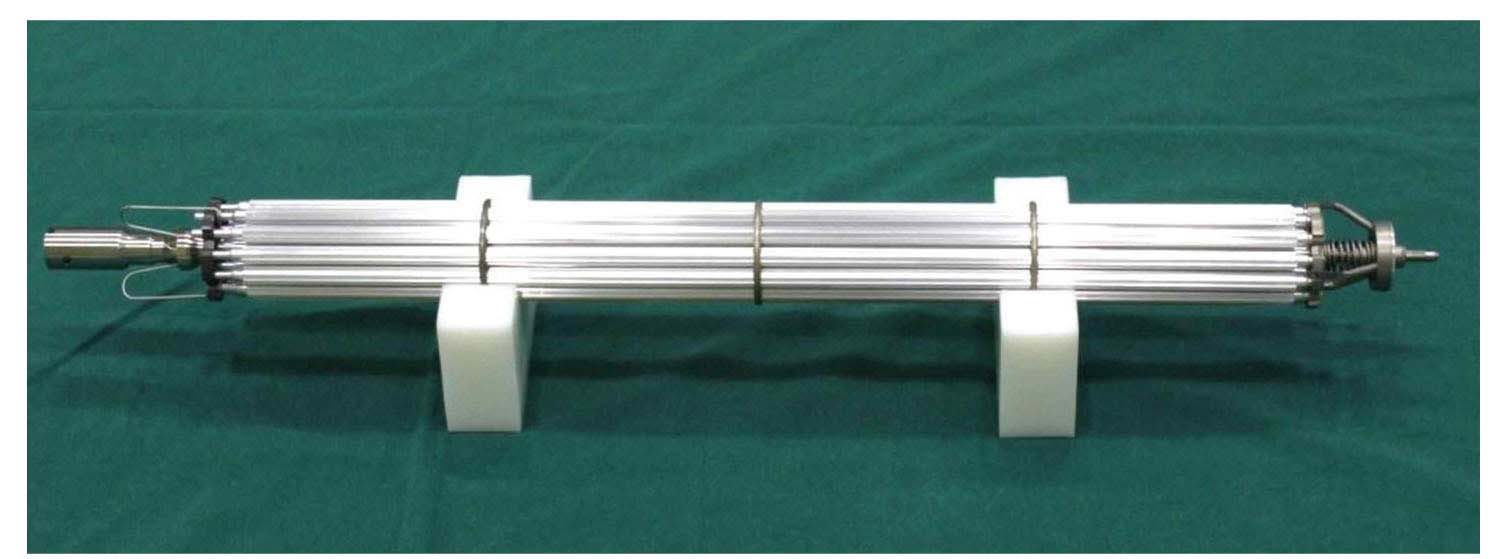
In Korea, the KOMO irradiation tests have been conducted at HANARO in Korea Atomic Energy Research Institute (KAERI) to qualify the rod-type dispersion fuel with atomized U-Mo powder dispersion in an Al matrix [18-20]. The objectives of the KOMO irradiation tests are to prepare for the possible upgrade of the HANARO core, to reduce the volume of spent fuel generation, and to improve fuel development capabilities. Details of the KOMO irradiation tests from KOMO-1 to KOMO-5 are summarized in Table 1, and the typical shape of the irradiation test fuel assembly is presented in Fig. 1.
The post-irradiation examinations (PIE) of the irradiated KOMO test samples were conducted at the Irradiated Materials Examination Facility (IMEF) in KAERI. The fuel swelling, interaction layer (IL) thickness, and oxide thickness were characterized according to different fuel fabrication parameters and irradiation conditions through observing the microstructural changes of the irradiated fuel samples. An overview of all KOMO irradiation test results and in-depth analyses are beneficial to extending understanding of the irradiation behavior of U-Mo fuel because the irradiation conditions of the KOMO tests are distinct compared with plate fuel tests: the KOMO test fuel has significantly higher fuel temperatures at similar fission rates.
2. SIGNIFICANT RESULTS FROM THE KOMO IRRADIATION TESTS
2.1 KOMO-1 Irradiation Test Results
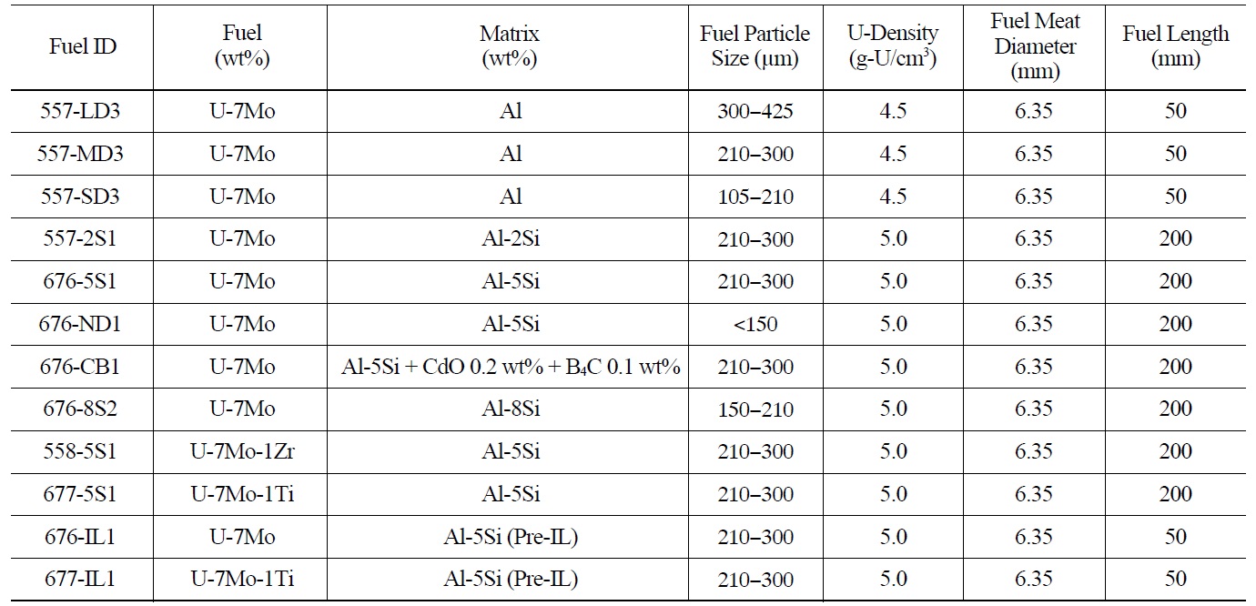
The KOMO-1 test aimed at the qualification of the full size U-Mo dispersion fuel rods for the possible upgrade of HANARO[20-21]. 10 fuel rods with four different types were selected for the irradiation test; the details of these rods are listed in Table 2. Two different Mo contents (7 and 9 wt.%)
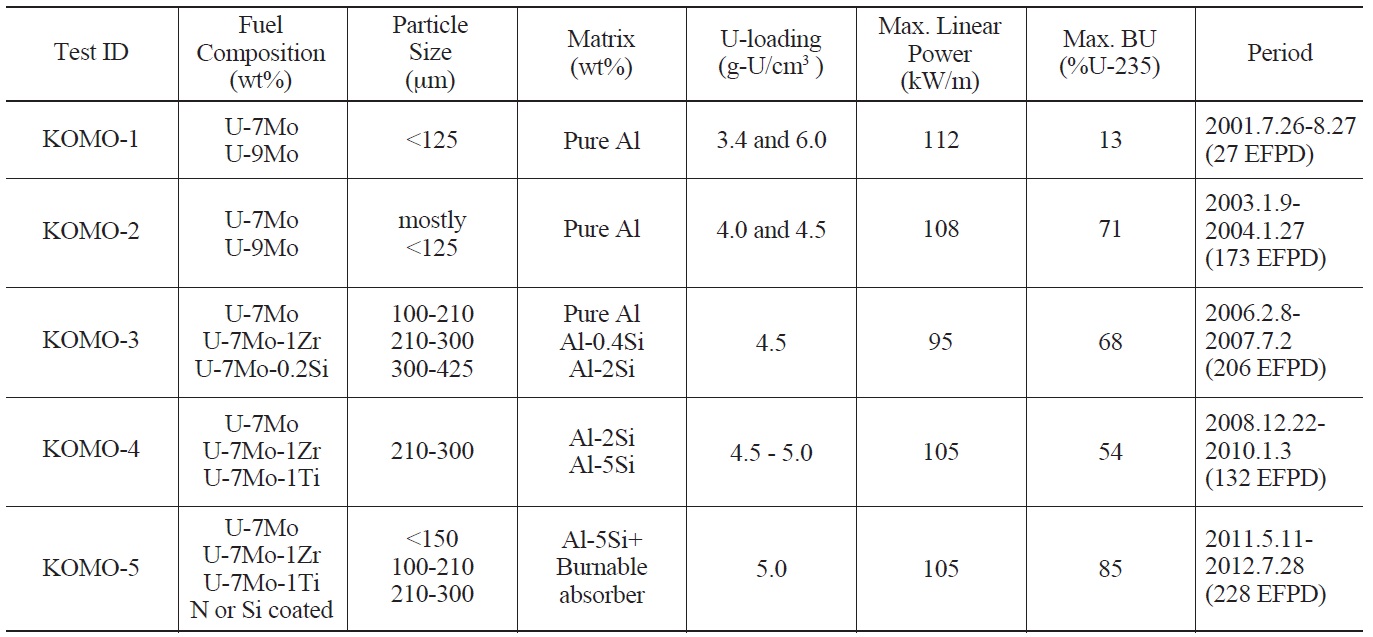
[Table 1.] Parameters of the KOMO Irradiation Tests at HANARO

Parameters of the KOMO Irradiation Tests at HANARO
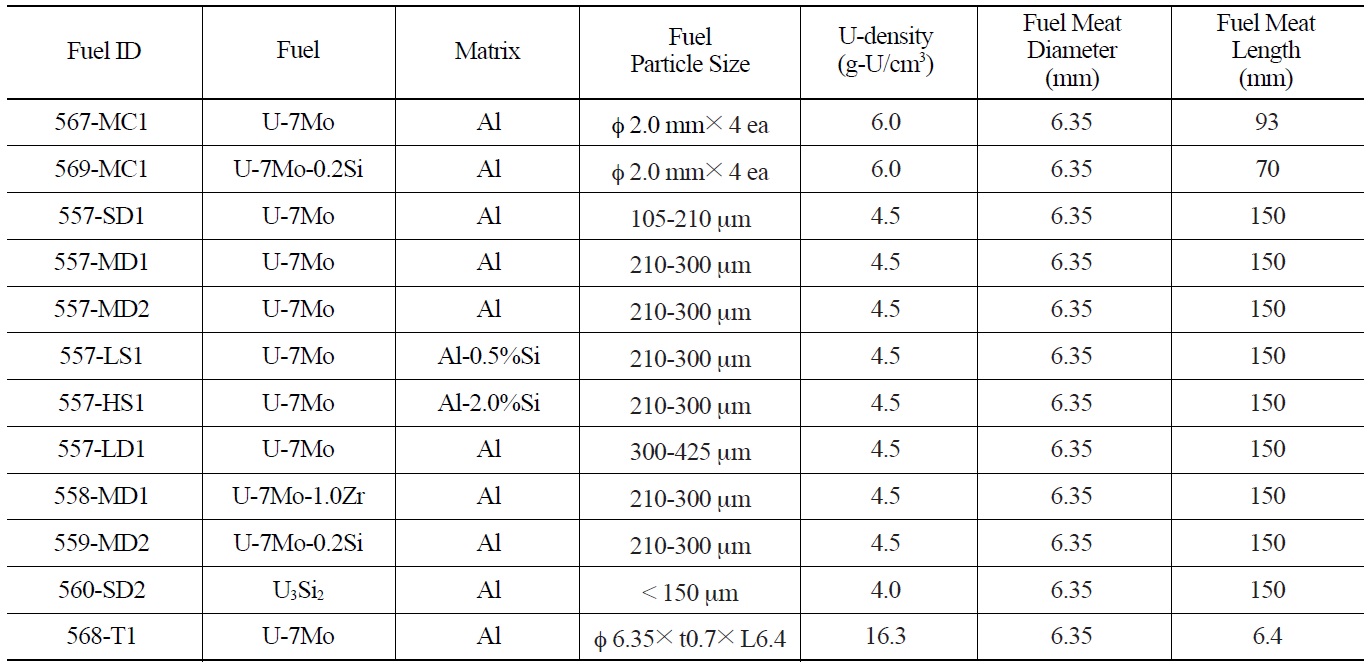
[Table 2.] Irradiation Conditions of the KOMO-1 Test Fuels
Irradiation Conditions of the KOMO-1 Test Fuels
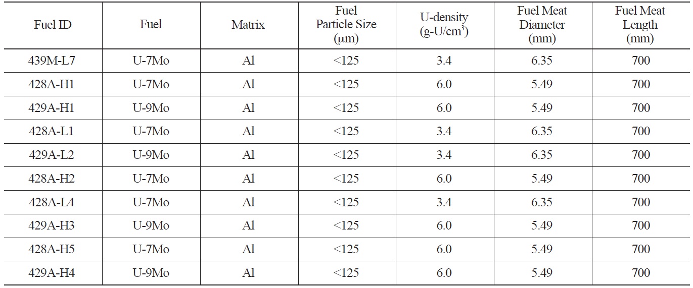
and two different uranium loadings (3.4 and 6 g-U/cm3) were adopted. A uranium density of 3.4 g-U/cm3 for the U-Mo dispersion fuel is equivalent to the uranium density of the U3Si dispersion fuel currently used in HANARO in terms of neutronics, which is 3.15 g-U/cm3. The fuel meat diameter of a standard fuel rod is 6.35 mm and the diameter reduced for higher density fuel is 5.49 mm, where the fuel meat indicates the zone with the mixture of U-Mo and Al. The length of fuel meat is 700 mm and the maximum particle size of the U-Mo powder is smaller than 125 μm, as proposed in the conventional U3Si2 fuel specifications[22].
The test fuel assembly containing 10 U-Mo dispersion rods was loaded in the OR-5 hole at HANARO on June 26, 2001. The U-Mo fuel assembly was discharged from the HANARO core on August 27, 2001, right after detecting high coolant radioactivity. On the cladding of the fuel rod with 6.0 g-U/cm3 irradiated at the highest power, an axial cleavage was observed. The U-Mo test rods were irradiated for 26.6 effective full power days (EFPD). Calculation of the linear power of the failed fuel region indicated that the maximum power was 107.1 kW/m. The peak burnup of the failed fuel rod was calculated to be 12.9 at.% depletion of the initial enrichment of 19.75% U-235 in low enriched uranium (hereafter, 12.9% U-235).
The smooth cleavage surface at the failure zone was associated with the debonding of the cladding along the weak interface formed during the co-extrusion process. The fuel meat cross-section of the region where the cleavage occurred exhibited the Al matrix being almost depleted due to interaction between the fuel particles and Al, except in the fuel meat periphery. However, the fuel cross-section at the axial top position of the fuel rod exhibited little interaction due to the low temperature at low power.
The volume expansion (or swelling) of fuel meat occurs through interaction product formation of the Al matrix with the fuel particles, fission gas bubble formation, and
[Table 3.] Swellings of Fuel Meats Measured using the Immersion Method
Swellings of Fuel Meats Measured using the Immersion Method
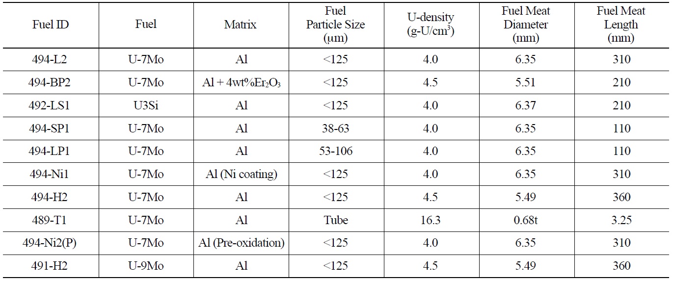
[Table 4.] Irradiation Conditions of the KOMO-2 Test Fuels

Irradiation Conditions of the KOMO-2 Test Fuels
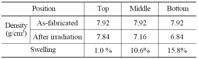
lattice swelling by solid fission products[23]. The swelling by the fuel-Al interaction primarily occurs as a result of the formation of a low density interaction product[24]. The fuel meat swelling was measured using the immersion method and the results are presented in Table 3. The high powered region (bottom) exhibited significantly higher swelling than the low powered region (top).
Although the failure of the full-sized U-Mo dispersion fuel with 6.0 g-U/cm3 U-density was associated with a fabrication defect in the cladding, the U-density of the later tests was maintained at or below 5.0 g-U/cm3 for safety. Because the IL growth of U-Mo and Al was significant in the 6.0 g-U/cm3 U-Mo dispersion fuel and because the IL has low thermal conductivity, the fuel temperature under normal operation was too high and reached an unacceptable level. Hence, the fuel temperature is considered as critical as other safety evaluation parameters. The calculated beginning-of-life (BOL) temperature was approximately 270 ℃ at the fuel meat center of the highest powered fuel rod. The volume expansion caused by the IL growth, which is primarily affected by the temperature, was greater than the fission product-induced swelling that resulted from the fission gas bubble growth and lattice expansion. The fission product-induced swelling was low due to the low burnup of approximately 13% U-235.
2.2 KOMO-2 Irradiation Test Results
In the second irradiation test, the uranium densities of the U-Mo dispersion fuels were lowered from 6.0 g-U/cm3 to 4.5 g-U/cm3 or 4.0 g-U/cm3 in order to avoid the problem of severe IL formation[25-27]. One U-Mo monolithic ring with Al cladding was also included. As shown in Table 4, a standard fuel rod with a diameter of 6.35 mm, containing U-7 wt.% Mo dispersion fuel with 4.0 g-U/cm3, and a reduced fuel rod with a diameter of 5.49 mm, containing U-7Mo dispersion fuel with 4.5 g-U/cm3, were prepared. The two U-7Mo dispersion fuel rods with different U-Mo particle sizes were loaded in order to examine the effect of the U-Mo particle size. Two U-7Mo dispersion fuel rods with pre-oxidized cladding or Ni-coated cladding were included in order to investigate the influence of the cladding surface treatment. A U-7Mo dispersion fuel rod with a burnable absorber of 4 wt.% Er2O3, a U-9 wt.% Mo dispersion fuel rod, and a U3Si dispersion fuel rod were also loaded.
The irradiation test assembly was loaded in the OR-5 hole of HANARO on January 9, 2003, and was discharged on March 7, 2003 for a visual inspection. After being reloaded on June 5, 2003, the irradiation test assembly was finally discharged on January 27, 2004. The average burnup was calculated to be 60.8% U-235 and the maximum local burnup was 71.2% U-235.
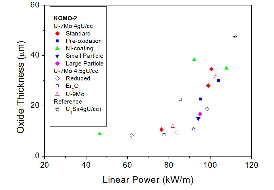
The measured thickness of the cladding oxide layer exhibited an approximately linear correlation with the power, if the low power data are neglected, as shown in Fig. 2. The effect of the surface treatments on the oxidation were negligible because the pre-oxidation-treated fuel rod (494-Ni2(P)) and Ni-coated fuel rod (494-Ni1) exhibited a thicker oxide layer formation.
The swelling of the irradiated fuel meat was measured using optical microscopic observations of the diameter change of the fuel meat after irradiation. The fuel meat swellings measured were in the range of 5.3 to 16.3%. The swelling data exhibited a linear correlation with the BOL temperature. The use of large fuel particles was effective in reducing the swelling. It is not certain that the lower fuel swelling in the fuel with a burnable absorber addition was due only to the lowered power.
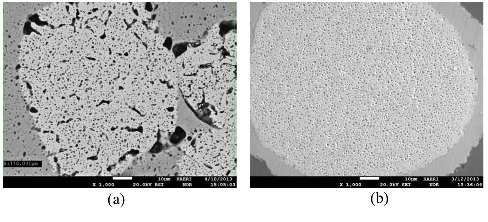
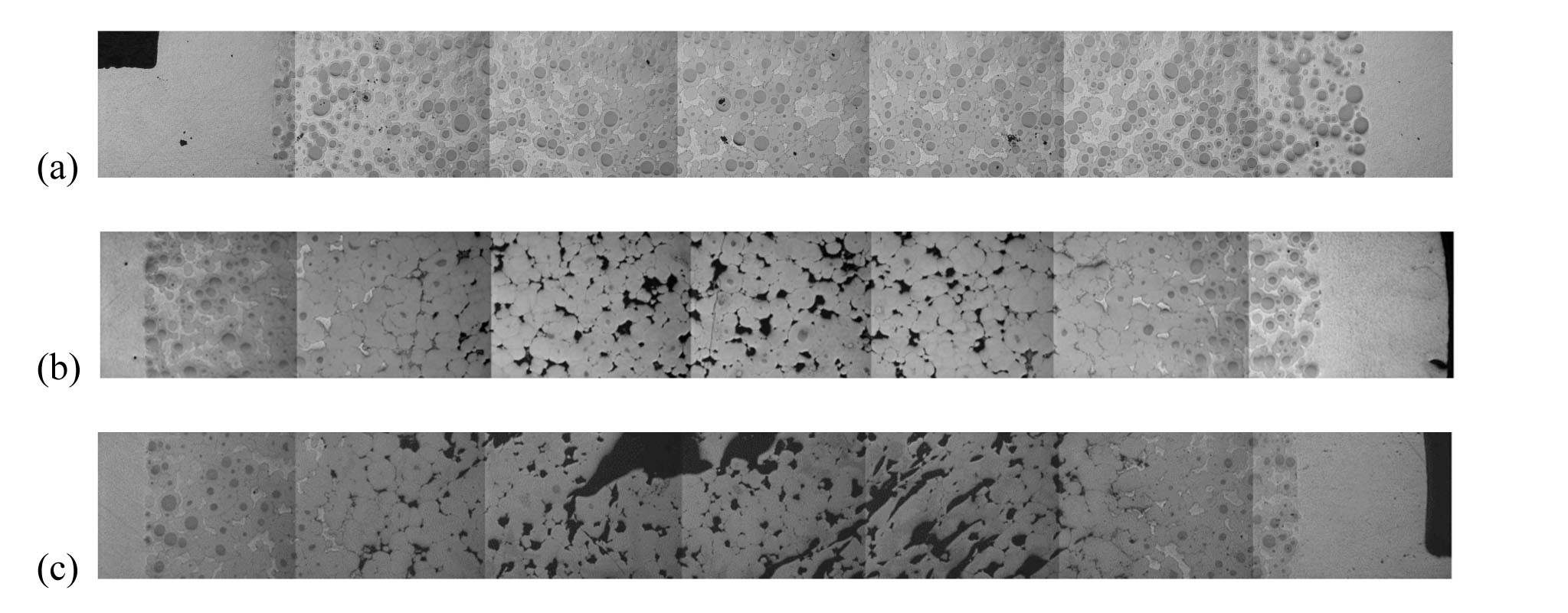
Figure 3 presents the optical micrographs of the crosssection of the 4 g-U/cm3 U-7Mo dispersion fuel rod at three different locations with local burnups of 50%, 62%, and 68%. When the local burnup was greater than 62%, almost all of the U-Mo fuel and the entire Al interacted to form a U-Mo-Al reaction phase. Pore-like voids were observed in the central region of the fuel meat, which was possibly due to a density change resulting from a complete reaction between U-Mo and Al. However, in the periphery area of the fuel rod, pore-like defects were not observed even after 68% burnup. The U-7Mo dispersion fuel with larger-than-standard size fuel particles (~80 μm) exhibited a sound microstructure: pore-like defects were not observed, which contrasts with other dispersion fuels with small sized fuel particles (~50 μm), as shown in Fig. 4. The U- 9Mo dispersion fuel rod exhibited a more stable performance than U-7Mo.
In the KOMO-2 irradiation test, the active feedback of the IL growth and fuel temperature was significant because it affected the final microstructure of the U-Mo dispersion fuel. Because the thermal conductivity of the fuel meat is primarily determined by the volume fraction of the Al matrix, the consumption of the Al matrix significantly reduces the meat thermal conductivity when the IL growth is high at a high temperature[28]. Generally, the temperature history of the research reactor fuel during irradiation is not required because it is not sufficiently high to generate performance issues; however, the PIE results of KOMO-2 demonstrated that the fuel temperature must be known. The KOMO-2 test rods demonstrated that the fuel temperatures increased with burnup due to the IL growth, although the power decreased during the test. Due to the larger specific interfacial area between the U-Mo particles and the Al matrix for the fuel meat with smaller U-Mo particles, the fuel meat formed a larger volume fraction of ILs than that with the larger U-Mo particles in the same irradiation conditions[29-30]. Therefore, the use of larger fuel particles is recommended for reducing the IL growth.
2.3 KOMO-3 Irradiation Test Results
The KOMO-3 test examined several remedies for solving the problem caused by the IL growth between UMo and Al in U-Mo/Al dispersion fuel[31-32]. The remedies include the use of U-Mo fuel particles larger than the standard size, the addition of a small amount of Zr in the U-Mo, and the addition of a small amount of Si in the matrix Al. The uranium density was 4.5 g-U/cm3 and the particle size ranged between 210 and 300 μm.
[Table 5.] Irradiation Conditions of the KOMO-3 Test Fuels

Irradiation Conditions of the KOMO-3 Test Fuels
The irradiation test assembly consisting of 12 different fuel rods, as given in Table 5, was loaded in a HANARO reactor on February 8, 2006, and discharged on July 2, 2007, after 206 EFPD of irradiation. The maximum linear power of the dispersion fuels with 4.5 g-U/cm3 was slightly lower than that of the KOMO-2 fuels with the same uranium density. The average burnup was calculated to be ~54 at.% U-235 and the peak burnup was estimated to be ~68% U-235.
Because the burnup is constant for each fuel meat cross-section while the temperature differs radially, the effect of the temperature was investigated. In addition, the effect of the burnup was investigated between the two cross-sections because the fuel temperature at the crosssection periphery for the higher burnup location was the same as that of the fuel center of the cross-section for the lower burnup location.
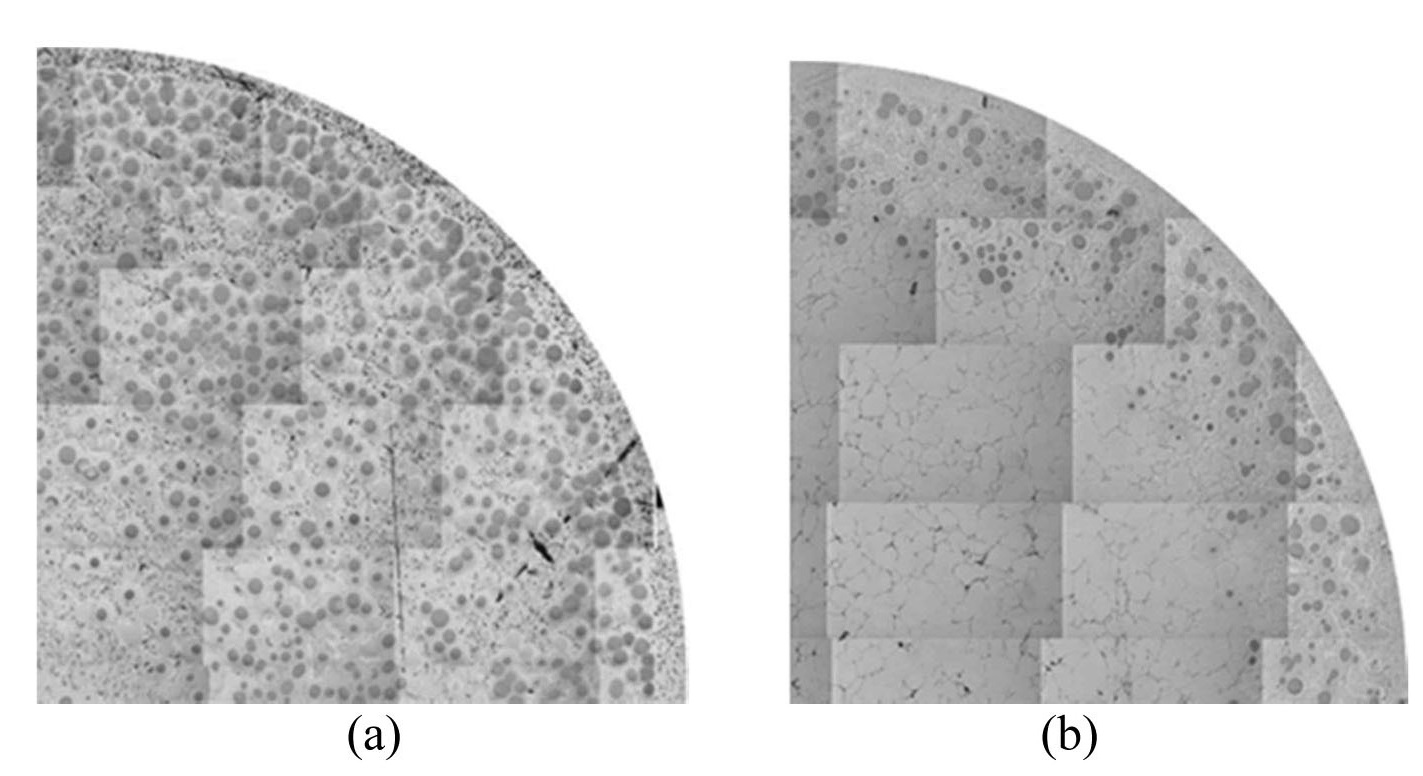
When compared with the KOMO-2 results (494-L2 and 494-H2) where U-Mo powders with normal size ranges (<125 μm) were used, the U-7Mo/Al dispersion fuel (4.5 g-U/cm3) containing large U-Mo particles (210-300 μm) exhibited better irradiation performance, as determined using the evolution of microstructures. The fuel with the larger fuel particles demonstrated that the ILs have not been developed extensively, as shown in Fig. 6(a). The use of large U-Mo particles reduces the total interfacial area between the U-Mo and Al matrix and, as shown in the irradiated microstructure, it results in a relatively small fraction of IL. This consequently leads to a smaller increase of fuel temperature during irradiation.
The U-7Mo/Al has an IL thickness of ~70 μm at the center and ~25 μm at the periphery, whereas the U-7Mo-1Zr and U-7Mo/Al-2Si have decreased IL thicknesses of 40-50 μm. The U-7Mo-1Zr/Al fuel exhibits a thinner IL
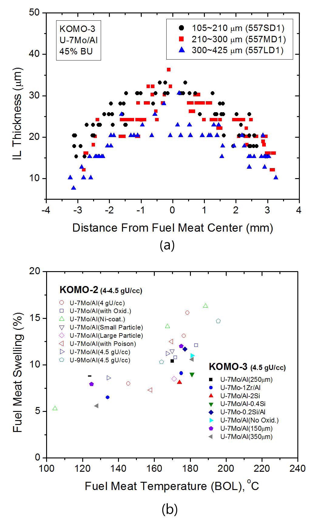
thickness (~50 μm) than that of the U-7Mo/Al fuel. The IL thickness of the U-7Mo/Al-2Si fuel is ~40 μm. Fuel swelling in the range of 8.1-10.4% was measured, which is considerably lower than the KOMO-2 results, as shown in Fig. 6(b).
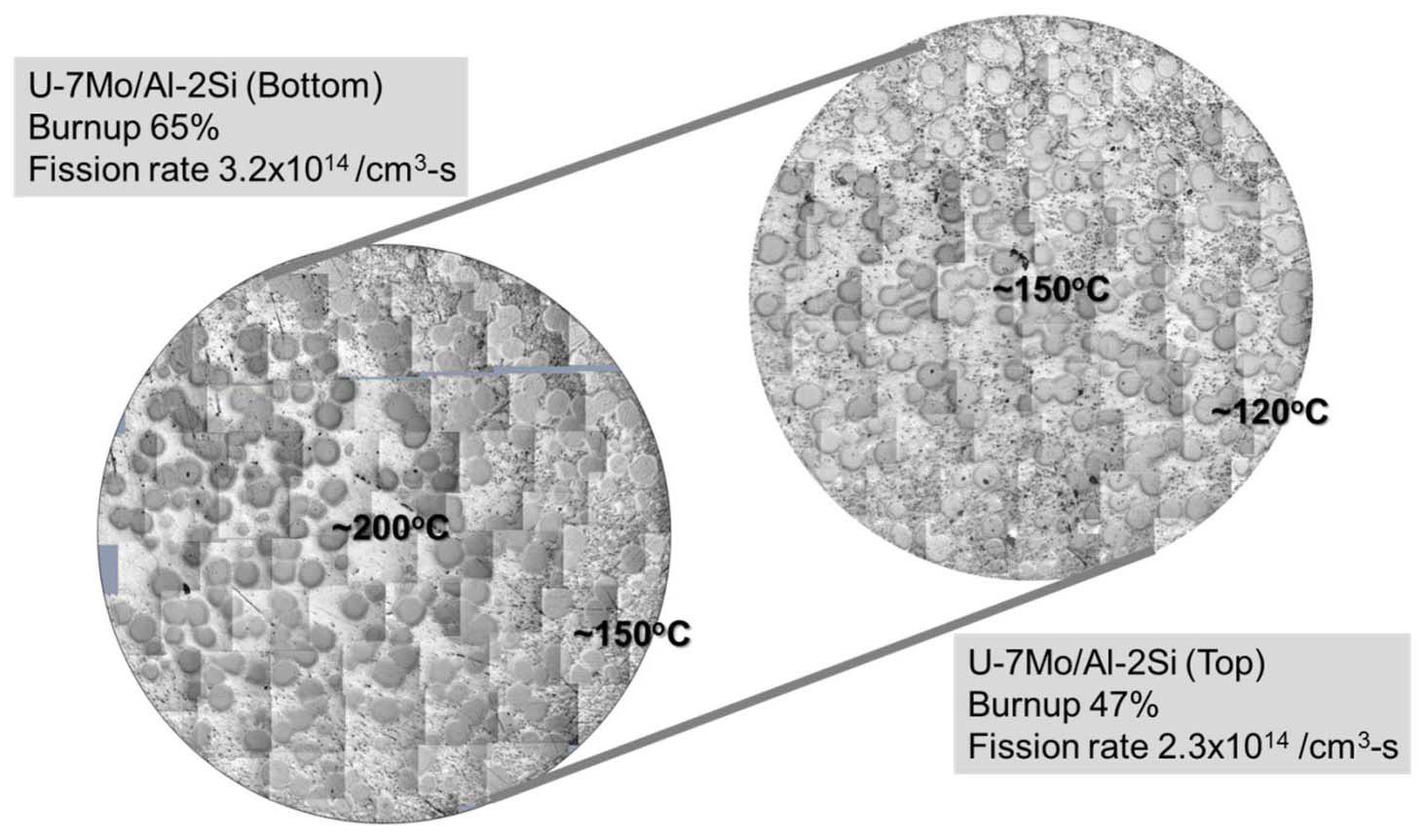
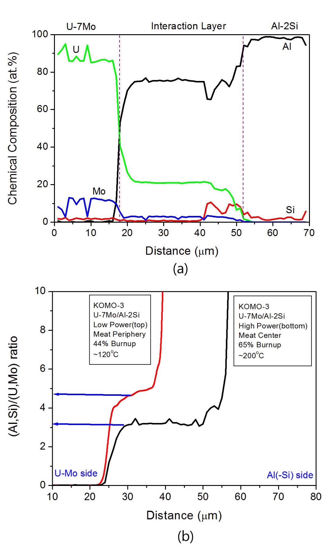
Accumulation of Si in the ILs of the irradiated U-7Mo/Al-2Si fuel was observed as shown in Fig. 7(a). While the out-of-pile annealing tests demonstrated that the Sirich layer was observed on the U-Mo side[33], the Si was accumulated on the Al side during the irradiation. When the IL compositions were measured at the fuel meat center with higher irradiation temperatures and at the meat periphery with lower irradiation temperatures, the U-7Mo/Al fuel had ILs with a composition of (U,Mo)Al3 at high temperatures and (U,Mo)Al4 at low irradiation temperatures, as shown in Fig. 7(b).
The calculated centerline temperature peaked at ~200 ℃ after 37% U-235 burnup. The prediction for a similar fuel (494-H2, 4.5 g-U/cm3) from the KOMO-2 test demonstrated that the peak temperature was ~480 ℃. Because the use of large U-Mo particles was the only difference from the KOMO-2 tests, the significantly lower fuel temperature is attributed to the effect of using the large fuel particles. The effect of large U-Mo fuel particles can be further enhanced through simultaneous modifications of the fuel with Zr or Ti and the matrix with Si.
The KOMO-3 test samples demonstrated that the reduced IL formation resulted from the use of larger U-Mo particles with a size range of 105 to 425 μm, which is unconventional. The temperature of the dispersion fuel with large U-Mo particles was not significantly affected by the formation of IL up to 70 μm, because the IL volume fraction remained insignificant. Both the addition of Zr in the U-Mo and the addition of Si to the Al matrix exhibited positive effects retarding the IL growth. The compositional analyses demonstrated that the addition of Si does not always reduce the (Al,Si)-(U,Mo) ratio, because the ratio is a function of the irradiation temperature and a higher ratio was observed in a low temperature region[34]. The Si distribution was not uniform throughout the IL and more Si was accumulated at the interaction/matrix boundary. However, the higher Si content measured in the U-Mo side in a higher temperature region necessitated out-of-pile annealing in order to form Si-rich preformed layers[35,36].
2.4 KOMO-4 Irradiation Test Results
The primary objectives of the KOMO-4 tests were determining the optimum Si content in the matrix and
[Table 6.] Details of the KOMO-4 Test Fuel Rods
Details of the KOMO-4 Test Fuel Rods
examining the effect of a third element addition (Ti or Zr) to U-Mo with a combination of the Al-Si matrix at high temperatures of ~200 ℃[37]. Seven 5.0 g-U/cm3 U-Mo- X (X = Zr, Ti)/Al-xSi (x = 2, 5, 8 wt.%) dispersion fuels and three 4.5 g-U/cm3 U-7Mo/Al dispersion fuels with different fuel particle sizes (105-210 μm, 210-300 μm, and 300-425 μm) were tested. In addition, two pre-irradiation annealed samples were investigated for the effectiveness of pre-irradiation-formed Si-rich layers on the U-Mo particles.
Details of the KOMO-4 test fuels are listed in Table 6. The irradiation test assembly was loaded in the OR-3 hole at HANARO on December 22, 2008, and it was discharged on January 3, 2010, after 132.1 EFPD of irradiation. From the KOMO-4 tests, the test assembly maintained its directionality over the irradiation cycle in order to obtain precise power histories of the each fuel rod.
The average burnup was calculated to be 47.1% and the maximum local burnup was 55%. The maximum linear power of the dispersion fuels with mostly 5.0 U-density was slightly higher than that of the KOMO-3 fuels that had 4.5 g-U/cm3. The swelling was measured from the diameter change measurements before and after irradiation, in which 3.9-8.8% (ΔV/V) were obtained for all test samples. The thicknesses of the oxide layers at the cladding surface were measured to be in the range of 40-50 μm after ~50% U-235 burnup.
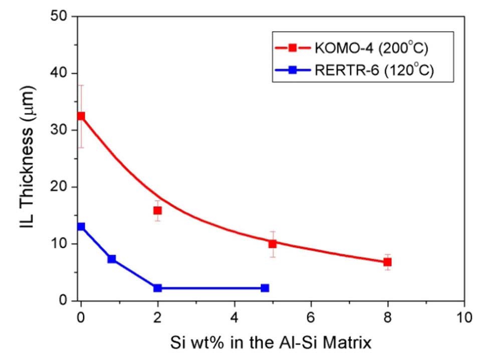
In general, the cross-section microstructures of the KOMO-4 fuel meats at a local burnup of ~50% U-235 indicate that neither extensive IL phases between U-Mo and the matrix, nor pore-like defects were formed. The IL thickness in the U-7Mo/Al-xSi (x = 0, 2, 5, 8 wt.%) decreased with an increasing Si content in the Al matrix, as shown in Fig. 8[38].
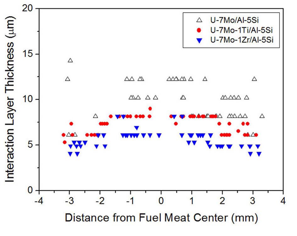
The additions of Ti and Zr to the U-Mo both reduced the IL growth further. Figure 9 demonstrates that the IL thicknesses of the U-7Mo-1Ti/Al-5Si and U-7Mo-1Zr/Al- 5Si fuels were ~8 μm and ~6 μm, respectively, which is slightly lower than the IL thickness of the U-7Mo/Al-8Si fuel[39].
The preheated U-7Mo/Al-Si and U-7Mo-1Ti/Al-5Si samples with a Si-rich IL with a thickness of 8-10 μm were irradiated and the IL grew slightly more (~5 μm) during irradiation. The electron probe micro-analysis (EPMA) also revealed that the initial 40 at.% Si in the preformed layer in the pre-annealed U-7Mo/Al-5Si sample was attenuated uniformly to less than 20 at.% Si as the IL grew further during the irradiation.
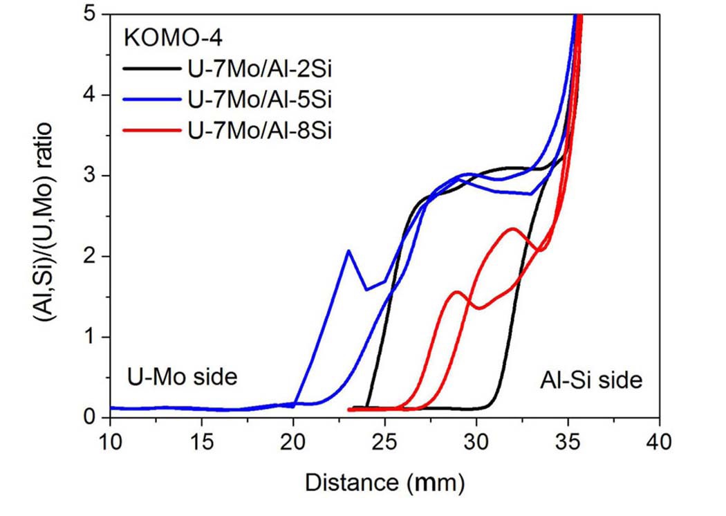
The EPMA analysis of the ILs of the irradiated UMo/ Al-Si samples was conducted and demonstrates that the Si creates a mount near the matrix. Nevertheless, it remains effective in reducing the IL growth. The EPMA analysis also revealed that the (Al,Si)/(U,Mo) ratio in the IL was less than 3 in the samples with additional Si, as shown in Fig. 10.
The effects of the Si addition to the Al matrix on the interaction was demonstrated clearly in the KOMO-4 tests as varying the Si content from 2 to 8 wt.% resulted in a progressive decrease in the IL thickness. This indicates that 5 wt.% of Si is not sufficient for limiting the IL growth when the ILs maintain their growth during the irradiation. When the Si addition to the Al matrix was combined with the alloying of Ti or Zr in the U-Mo, a synergic effect in reducing the interaction was obtained. The behavior of the fuel rod samples with preformed Si-rich layers was not significant.
2.5 KOMO-5 Irradiation Test Results
The primary objectives of the KOMO-5 tests were qualification of full-sized 5 g-U/cm3 U-7Mo-(Ti,Zr)/Al- 5Si fuel rods with burnable absorbers (B4C, CdO, Er2O3) and investigation of the irradiation behavior of silicidecoated or nitride-coated U-7Mo particles[40,41].
The KOMO-5 test was irradiated in HANARO for 238 EFPD from May 23, 2011, to July 28, 2012[42]. The average and maximum burnups for the full-size fuel rods were calculated as 71% and 85%, respectively. The KOMO- 5 test assembly consisted of 12 dispersion fuel rods; Table 7 lists the design parameters of the KOMO-5 test samples. Four full-size fuel rods with a length of 700 mm and a diameter of 5.49 mm contained burnable absorbers, including B4C, CdO, and Er2O3 in combination. Five fuel rods with silicide-coated or nitride-coated U-Mo or U-Mo-Ti and three pre-irradiation annealed fuel rods were also prepared.
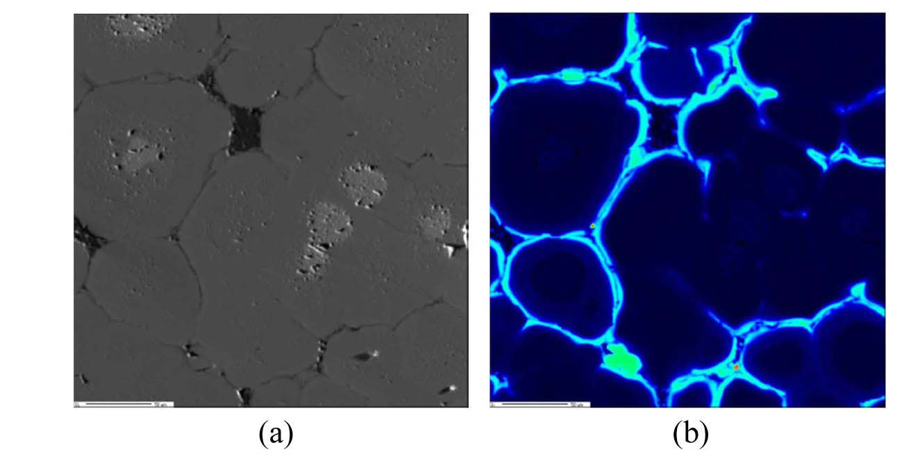
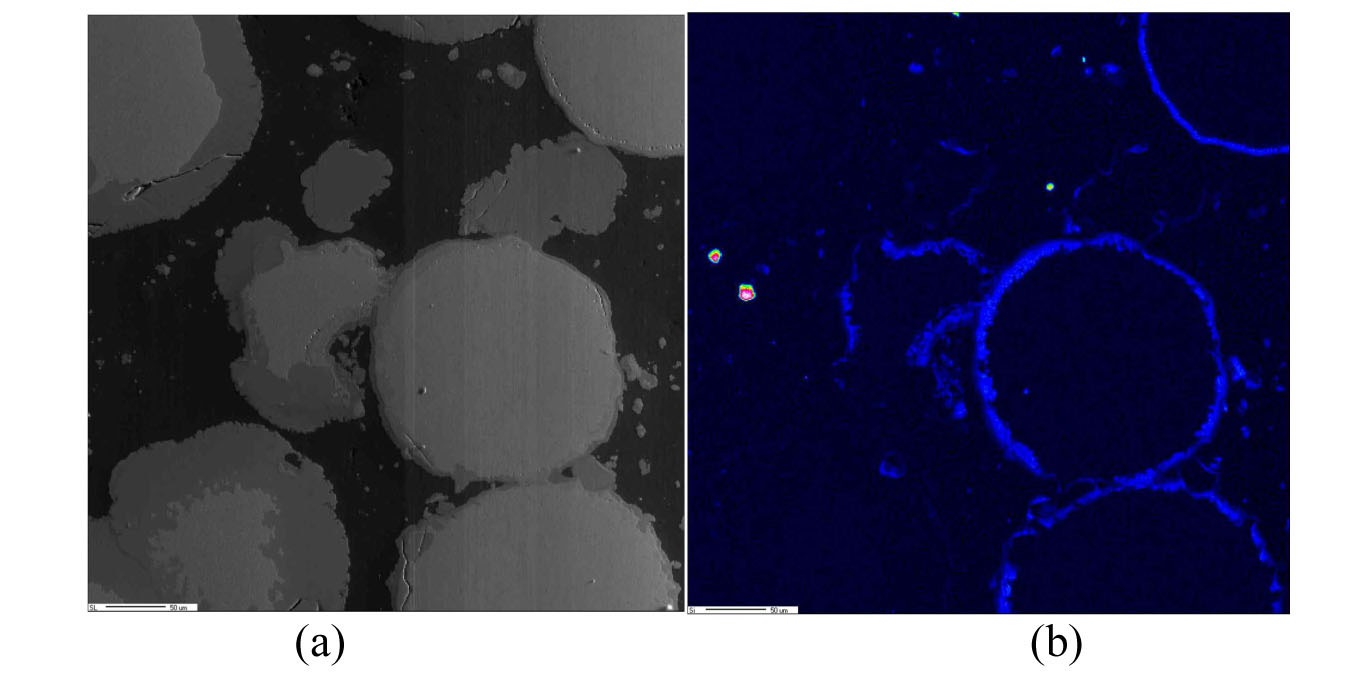
Full consumption of the Al matrix was observed at the fuel meat center of the U-7Mo/Al-5Si fuel rod with an average U-Mo particle size of 70 μm when it was irradiated to 83% U-235 burnup, while the silicide-coated or nitride-coated U-Mo dispersion fuels did not exhibit significant interaction development around the U-Mo particles in a pure Al matrix. The EPMA analyses of the ILs demonstrated that the Si in the Al-Si matrices accumulated at the outer rim of the ILs as shown in Fig. 11.
[Table 7.] Details of the KOMO-5 Test Fuel Rods

Details of the KOMO-5 Test Fuel Rods
In the dispersion fuel sample with silicide-coated UMo, a mixed distribution of thick ILs and thin ILs was observed as seen in Fig. 12. When compared with the IL thicknesses of the well-coated particles, the silicide-coated particles had thinner ILs than the nitride-coated particles. The ILs in the silicide-coated U-7Mo/Al-2Si and silicidecoated U-7Mo-1Ti/Al samples were significantly more uniform than those in the silicide-coated U-7Mo/Al sample.
Figure 13 compares the scanning electron cross-section images of the full-sized fuel rods of U-7Mo/Al-5Si (83% U-235) and U-7Mo-1Ti/Al-5Si (83% U-235). The U-7Mo- 1Ti/Al-5Si exhibited smaller fission gas bubbles and thinner IL thicknesses than the U-7Mo/Al-5Si. The IL thickness of the U-7Mo-1Ti/Al-5Si was only ~10 μm, while it was ~40 μm for the U-7Mo/Al-5Si.
The KOMO-5 results demonstrated that the Si accumulated at the IL-Al boundary accumulated as the IL grew, so the Si always remained at the boundary. It was observed that the silicide coating layer on the U-Mo particles better
blocked the interdiffusion of Al than the nitride coating layer. The addition of Ti or Zr not only had a positive effect on reducing the IL growth, but it also appeared to have an advantageous effect in suppressing the fission gas bubble swelling in the U-Mo fuel.
The KOMO irradiation tests of atomized U-Mo dispersion fuel rods at HANARO successfully demonstrated the sound fuel performance of the U-Mo dispersion fuels of 4-5 g-U/cm3 up to 85% U-235 burnup at irradiation temperatures of ~200 ℃. Moreover, the systematic postirradiation examinations of the KOMO test fuel samples added important data regarding the irradiation behavior of atomized U-Mo dispersion fuels. The significant observations from the KOMO tests are summarized as follows.
Rod-type U-Mo dispersion fuel has not exhibited breakaway swelling resulting from the active coalescence of fission gas bubbles in the amorphous ILs due to the higher mechanical constraints of the rod design than those of the plate design.
The KOMO tests provided valuable data that were obtained for higher temperatures at similar powers, i.e., fission rates, than those available from the plate fuel tests.
The Si in the Al-Si matrices accumulated at the outer rim of the ILs instead of spreading evenly across the ILs as was seen in the out-of-pile tests. A higher Si addition in the Al matrix resulted in a stronger suppressing power on the IL growth.
The (Al,Si) to (U,Mo) ratio in the IL of the U-Mo/Al-Si dispersion fuel was lower than that in the U-Mo/Al dispersion fuel at the same temperature. The ratio is known to be dependent on the fuel temperature. The lower (Al,Si) to (U,Mo) ratio is believed to be more advantageous because it is stronger in suppressing pore formation in the IL.
The addition of Ti or Zr to the U-Mo when combined with the addition of Si to the Al matrix was more effective in reducing the IL growth than the Si addition to the Al matrix alone.
The beneficial effect of using large U-Mo particles in reducing the IL growth was confirmed repeatedly in the KOMO tests. Therefore, if the industrial fabrication of uniform dispersion of large particles is feasible, we recommend their use.
The nitride-coated and silicide-coated U-Mo particles exhibited a reduction in the IL growth. Between these, the silicide-coated particles performed better. Therefore, further study in this method is worthwhile together with development of a better coating technology.


![Variation of the Oxide Thicknesses with the Linear
Power of the Fuel Rods in the KOMO-2 Test[26].](http://oak.go.kr/repository/journal/12978/OJRHBJ_2013_v45n7_847_f002.jpg)
![Optical Micrographs of 4.0 g-U/cm3 U-7Mo Dispersion Fuel Rods (494-L2) at Three Locations with Different Powers and
Burnups: (a) 50%, (b) 62%, and (c) 68% [27].](http://oak.go.kr/repository/journal/12978/OJRHBJ_2013_v45n7_847_f003.jpg)
![Effect of Fuel Particle Size on IL Formation during
Irradiation: (a) Coarse U-Mo Particles and (b) Fine U-Mo
Particles[27].](http://oak.go.kr/repository/journal/12978/OJRHBJ_2013_v45n7_847_f004.jpg)

![(a) Radial Distribution of the IL Thicknesses of the
Irradiated U-Mo/Al Dispersion Fuels using Different-size U-Mo
Particles. (b) The Variation of Fuel Swelling with Fuel
Meat Temperatures[32].](http://oak.go.kr/repository/journal/12978/OJRHBJ_2013_v45n7_847_f006.jpg)
![(a) Compositional Analysis Results of U-7Mo/Al-2Si
(557-HS1) at Fuel Meat Center. (b) Comparison of the (Al,Si)
to (U,Mo) Ratios of a Low Power Cross-section and a High
Power Cross-section[35].](http://oak.go.kr/repository/journal/12978/OJRHBJ_2013_v45n7_847_f007.jpg)