검색 전체 메뉴
PDF
맨 위로
OA 학술지
Development of a Four-way Interface for Online Capillary Isoelectric Focusing-Electrospray-Mass Spectrometry (CIEF-ESI-MS)
  • 비영리 CC BY-NC
  • 비영리 CC BY-NC
ABSTRACT
Development of a Four-way Interface for Online Capillary Isoelectric Focusing-Electrospray-Mass Spectrometry (CIEF-ESI-MS)
KEYWORD
CIEF-ESI-MS , Interface , Carbonic anhydrase I , Fourier transform mass spectrometry
  • Introduction

    Conventional isoelectric focusing allows separating the amphoteric compounds such as peptides, proteins in slab gels according to their isoelectric point (pI).1 Capillary isoelectric focusing (CIEF) was first introduced by Hjerten et al.2 in 1985, which was performing isoelectric focusing within a fused silica capillary without slab gels. A mixture of carrier ampholytes and analytes is loaded into a separation capillary. Separation is based on the focusing of analytes and carrier ampholytes at locations of inherent isoelectric points within a pH gradient across the capillary under high voltage. There are three discrete steps for performing CIEF, loading, focusing and mobilization. Sample mixed with carrier ampholytes is loaded through the whole column from the inlet to the outlet. After sample loading, focusing proceeds with applying high voltage across the capillary. The pH gradient forms by solutes migration to the appropriate position along the gradient and analytes are separated by their pI values. After the focusing was completed, it is necessary to mobilize or elute the contents of the capillary past a detector installed at the end of capillary (outlet bounce). CIEF is an alternative to the traditional slab gel electrophoresis because it allows fast and automated analyses with high resolution and requires small sample amount.

    Coupling CIEF with mass spectrometry (MS) by electrospray ionization was first demonstrated by Tang et al.3 The CIEF-ESIMS has been more powerful techniques providing information for protein structures and characterization based on their pI and molecular weights,3-8 which is analogous to the conventional two-dimensional (2D) polyacrylamide gel electrophoresis (PAGE). However, in spite of its potential advantages and applications for protein analysis, online CIEF-MS coupling using ESI interfaces presents several technical difficulties. First, most of the traditional CIEF reagents are not ESI compatible, such as strong inorganic acids and bases which are usually used for catholyte and anolyte. They can be replaced by volatile organic acids and bases for ESI-MS. Another big challenge was the carrier ampholytes that were coeluted with analytes, as they would suppress ionization of analytes and create spectral interferences. Coaxial sheath flow was introduced to interfacing capillary electrophoresis mass spectrometry (CE/MS) to enhance the performance of spray and reduce many of CE/MS limitations.9,10 The coaxial sheath flow (1-5 μ L/min) of liquid establishes the electrical contact with the CE effluent to the cathode of CE, which also provides electrospray voltage. This coaxial sheath flow was also applied to the electrospray process for CIEF-ESI-MS interfacing by Tang and co-workers using the Finnigan MAT electrospray kit.3 In this case, the CIEF capillary inlet end was put into the anolyte reservoir and the outlet end which was mounted within the electrospray probe was put into the catholyte reservoir during focusing. Once the focusing was completed, the electric potential was turned off and the outlet reservoir was removed, and the outlet end was reinstalled into the electrospray needle. During the mobilization step, the sheath liquid flow is delivered by liquid sheath tubes and two HV power supplies were used for delivering the electric potentials at the inlet electrode and at the electrospray needle. Clake and Naylor developed another strategy producing a static ‘hanging’ drop of catholyte at the tip of spray needle for focusing.6 In the focusing stage, the capillary column, filled with sample and ampholyte solution, was installed to pass through the electrospray needle (sheath liquid line) with its tip a few milimeter outside the electrospray needle. Catholyte was delivered co-axially through the sheath liquid line enabling the formation of a static ‘hanging’ drop of catholyte at the tip of capillary column. During focusing, the hanging drop works as the catholyte reservoir for the CIEF. Once focusing was completed, the electrical potential was turned off and the sheath liquid line was flushed with sheath liquid solution (to be used for ESI). The end of capillary column was then repositioned to a distance of 0.5mm out of the spray needle. During analyte mobilization, the sheath liquid solution was co-axially delivered. Kuroda et al. installed the end of capillary through a modified stainless steel tubing in the laboratory-built CE system and was positioned ca. 0.5mm outside the outlet of the metal tubing.7 The coaxial sheath liquid was administered at a flow rate of 2 μ L/min through the metal tubing. These previous methods for interfacing CIEF and MS were preceded with electric discontinuity and reinstallation of the spray needle. Even in those cases, a line delivering catholyte liquid should be mechanically exchanged to a line for delivering sheath liquid.

    In this study, a new interface for CIEF and MS was developed using a four-way cross to deliver the catholyte and the sheath liquid within a single mechanical system. Four-way cross system does not need to stop the electricity neither to move the spray tip when starting the operation of CIEF/MS. In addition, the bare fused silica capillary was employed as a spray needle to produce stable electrospray as well as to guide the sheath liquid. The result in loading carbonic anhydrase I (CA I) onto the CIEF capillary column showed this new four-way cross interface and the new spray needle operated well providing a peak in electropherogram. Coupling with CIEF and FTMS showed a charge and isotopic distribution in mass spectrum.

    Experimental Section

      >  Materials

    Ammonium hydroxide and acetic acid were purchased from Sigma (St. Louis, MO, USA). Pharmalyte (pH 3-10; GE Healthcare) was used as a carrier ampholyte to generate a pH gradient at 25 kV. Samples were desalted using Millipore Amicon Ultra-0.5 mL centrifugal filter and premixed with the carrier ampholyte (final concentration of 1%, v/v). Then samples were centrifuged at 12000 rpm for 10 min and subjected to sonication to remove gas bubbles.

      >  CIEF-ESI-MS

    The column length was 100 cm (70 cm effective length for CIEF-UV). Ammonium hydroxide (~1%, v/v, pH ~9.5) solution was used as the catholyte and acetic acid (~1%, v/v, pH ~2.6) solution was used as the anolyte. The entire column was filled with the sample which was prepared with 1% ampholyte. CIEF experiments were performed using PRINCE Crystal 650 CE system (Emmen, Netherlands) and UV detection (Lambda 1010 UV-Vis; Bischoff, Germany) was carried out at 280 nm. A constant voltage of 25 kV was applied during focusing (20 min) and hydrodynamic mobilization (~25 mbar). Mass spectra were acquired by 12 T Fourier Transform Mass Spectrometer (FTMS, Agilent, Lake Forest, CA, USA) in positive mode with 1.6 s scan rate. Mass range of FTMS was performed in m/z 600~2000. Sheath liquid solution consisted of 40% methanol, 58% water and 2% acetic acid (v/v/v) and delivered at a flow rate of 2 μL/min by a syringe pump. 3.5 kV was applied to the four-way cross for ESI spraying which was monitored by a CCTV camera to check the shape and stability of ESI.

      >  Preparation of Coated Column

    Hydroxypropyl cellulose (HPC) powder was dissolved in water at room temperature to a final concentration of 5% (w/w). The polymer solution was left overnight to eliminate bubbles. The capillary column was filled with the HPC solution by a syringe pump, and the excess solution was drained out by using N2 gas at 30 psi. The polymer layer coated on the capillary inner wall was immobilized by heating from 60 ℃ to 140 ℃ at 5 ℃/min and then keeping at 140 ℃ for 20 min in a gas chromatographic oven with N2 gas at 30 psi.

    Results and Discussion

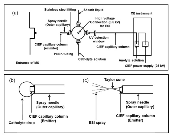
    Figure 1(a) demonstrates a diagram of the four-way interface for CIEF-ESI-MS. The new interface employed the four-way cross for delivering the catholyte and the sheath liquid separately. A CIEF capillary column was inserted from one port of the four-way cross and passed through the spray needle (sheath liquid line) installed at the opposite port of the four-way cross. The capillary column was fixed to protrude ca. 1 mm outside of the spray needle. The other two ports of the four-way cross were connected to lines delivering catholyte and sheath liquid separately. The catholyte or sheath liquid was delivered at a flow rate of 2 μL/min to the center of the four-way cross and flowed through the spray needle (inside the outer tube of CIEF capillary). For performing CIEF separation, the capillary column was filled with sample solution from the other end of the column (anode side). During focusing, catholyte was co-axially delivered to the end of spray needle for the formation of a “hanging drop” and the end of capillary column was soaked into the “hanging drop” (Figure 1(b)).

    The electric circuit for focusing was completed by applying high positive voltage (25 kV) at the anode side and grounding the cathode side (the body of four-way cross which is connected to the hanging drop by sheath liquid inside spray needle). In this experiment, a catholyte ‘hanging drop’ forms and drops away for every 6 minutes when the catholyte flow kept at 2 μL/min. Once focusing was completed, the mobilization step started with starting sheath liquid flow and stopping catholyte flow. In this way, liquid co-axially flowing through the spray needle was switched from catholyte to sheath liquid without manual exchanging of lines and electrical discontinuity. Then, 3.5 kV applied to the cross for producing ESI spray (Figure 1 (c)) with maintaining 25 kV at the anode side for keeping the pI gradient. Switching volume from catholyte to sheath liquid, which is composed of the volume from the center of the cross to the spray needle, was estimated to be 19 nL. The sheath liquid line can be switched from catholyte to sheath liquid within a minute. Therefore, in this design, CIEF focusing stage can be easily switched to the electrospray formation for MS detection of CIEF eluent without any mechanical changes of lines.

    In the early attempt for interfacing CIEF-MS, a commercial electrospray adapter kit or a modified metal tubing spray needle was employed to apply the high voltage for electrospraying.347 However, these metal spray needles

    had limitation to provide a stable spray with high voltage causing electric arching between the spray needle and the entrance for mass spectrometry in CIEF-MS system. In this study, a bare fused silica capillary was used as a spray needle (outer capillary). The inner dimension of the capillary spray needle (I.D. 530 μm) was larger than the outer dimension of CIEF capillary column (O.D. 360 μm), therefore the CIEF capillary column pass through and protrude beyond it at the ESI side. This double capillary needle system provided stable spray, enhanced the ionization efficiency and increased sensitivity.

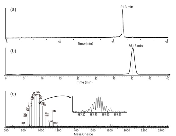
    Figure 2(a) shows a typical electropherogram of carbonic anhydrase I (CA I: pI 6.6, MW 28784) obtained by CIEFUV with typical setting and (b) shows a total ion electropherogram by CIEF-ESI-MS with newly designed four-way interface. An analytical capillary column (I.D. 50 μm, O.D. 360 μm) for CIEF separation was coated with 5% hydroxypropyl cellulose (HPC) solution twice and the method11 to coat a column is described in experimental section. Figure 2(b) proved that the new interface provides stable electrospray with overcoming limitations observed with previous systems using the metal tubing spray needle. Difference of migration time for CA I at 22.1 min by CIEFUV in Figure 2(a) and at 35.2 min by CIEF-ESI-MS in Figure 2(b) is due to the difference of effective length for CIEF-UV, as the detector was located at 30 cm from the end of the CIEF capillary. The hanging-drop focusing with four-way cross was well accomplished showing a peak in Figure 2(b). Figure 2(c) is the mass spectrum at 35.2 min showing charge state distribution from +36 (m/z 801) to +26 (m/z 1108) of CA I (m/z 1147 is an instrument noise). One of the charge state (+29, m/z 994) was enlarged in the circle of Figure 2(c) showing the isotopic mass distribution by FT/MS. It is noticed that the peaks for CA I on the electropherogram by CIEF-ESI-MS is somewhat wider than the peaks on the electropherogram by typical CIEFUV. Operational parameters, for examples rate of sheath flow, position of the tip of CIEF capillary at the ESI side, were under optimization to improve the separation resolution.

    Conclusions

    In summary, the new interface for online CIEF-ESI-MS was developed using the four-way cross. The fused silica capillary outer tubing facilitated the focusing and stable electrospray transferring catholyte or sheath liquid. The catholyte hanging-drop at the end of capillary column leaded the complete focusing shown on the reconstructed electropherogram of CA I. This single mechanical system with four-way cross could carry out CIEF-ESI-MS without washing the line, discontinuity of electric circuit and reinstallation of ESI tip. Coupling FT/MS with CIEF shows the isotopic mass distribution as well as the charge distribution of CA I in the mass spectrum. With further optimization of the operational parameters of the new interface, this online CIEF-ESI-MS can be performed for the complex protein samples by achieving protein separation according to their pI values.

참고문헌
  • 1. Righetti P. G. 1983 Isoelectric Focusing: Theory, Methodology and Applications google
  • 2. Hjerten S., Zhu M. D. 1985 [Journal of Chromatogr.] Vol.346 P.265
  • 3. Tang Q., Harrata A. K., Lee C. S. 1995 [Anal. Chem.] Vol.67 P.3515
  • 4. Tang Q., Harrata A. K., Lee C. S. 1997 [Anal. Chem.] Vol.69 P.3177
  • 5. Martinovic S., Berger S. J., Pasa-Polic L., Smith R. D. 2000 [Anal. Chem.] Vol.72 P.5356
  • 6. Clarke N. J., Naylor S. 2002 [Biomed. Chromatogr.] Vol.16 P.287
  • 7. Kuroda Y., Yukinaga H., Kitano M., Noguchi T., Nemati M., Shibukawa A., Nakagawa T., Matsuzaki K. 2005 [J. Pharm. Biomed. Anal.] Vol.37 P.423
  • 8. Mokaddem M., Gareil P., Varenne A. 2009 [Electrophoresis] Vol.30 P.4040
  • 9. Smith R. D., Olivares J. A., Nguyen N. T., Udseth H. R. 1988 [Anal. Chem.] Vol.60 P.436
  • 10. Pleasance S., Thibault P., Kelly J. 1992 [J. Chromatogr.] Vol.591 P.325
  • 11. Shen Y., Smith R. D. 2000 [J. Microcol. Separations] Vol.12 P.135
OAK XML 통계
이미지 / 테이블
  • [ Figure 1. ]  A schematic diagram of four-way interfacing for online CIEF-ESI-MS (a). A CIEF capillary column was placed through the four-way cross and extruded 1 mm from the spray needle which is bare fused silica capillary. The other ways of the cross were connected to sheath liquid and catholyte solution, respectively. Catholyte solution was delivered to the end of column and produced the “hanging-drop” catholyte during focusing step (b). The emitter of CIEF capillary column was soaked inside of the catholyte drop. After focusing was completed, the catholyte solution was stopped and the sheath liquid was delivered to the end of capillary column with applying 3.5 kV for ESI spray during mobilization step (c).
    A schematic diagram of four-way interfacing for online CIEF-ESI-MS (a). A CIEF capillary column was placed through the four-way cross and extruded 1 mm from the spray needle which is bare fused silica capillary. The other ways of the cross were connected to sheath liquid and catholyte solution, respectively. Catholyte solution was delivered to the end of column and produced the “hanging-drop” catholyte during focusing step (b). The emitter of CIEF capillary column was soaked inside of the catholyte drop. After focusing was completed, the catholyte solution was stopped and the sheath liquid was delivered to the end of capillary column with applying 3.5 kV for ESI spray during mobilization step (c).
  • [ Figure 2. ]  A typical electropherogram of CA I (pI 6.6, 0.1 mg/mL) acquired by CIEF-UV (a). A reconstructed electropherogram of CA I was acquired by four-way interfacing online CIEF-ESI-FTMS (b). The difference of migration time for CIEF-ESI-FTMS from that for CIEF-UV was due to the difference of effective length of analytical capillary column. The MS scan was accomplished over the m/z range 600 - 2500 with scan rate 1.6 s. The MS scan spectrum at retention time 35.15 min (c) showing the charge distribution of CA I from +36 to +26. The enlarged MS spectrum showed the isotopic distribution of charge state of [M+29H]29+ (m/z 994) indicating the resolution of FTMS.
    A typical electropherogram of CA I (pI 6.6, 0.1 mg/mL) acquired by CIEF-UV (a). A reconstructed electropherogram of CA I was acquired by four-way interfacing online CIEF-ESI-FTMS (b). The difference of migration time for CIEF-ESI-FTMS from that for CIEF-UV was due to the difference of effective length of analytical capillary column. The MS scan was accomplished over the m/z range 600 - 2500 with scan rate 1.6 s. The MS scan spectrum at retention time 35.15 min (c) showing the charge distribution of CA I from +36 to +26. The enlarged MS spectrum showed the isotopic distribution of charge state of [M+29H]29+ (m/z 994) indicating the resolution of FTMS.
(우)06579 서울시 서초구 반포대로 201(반포동)
Tel. 02-537-6389 | Fax. 02-590-0571 | 문의 : oak2014@korea.kr
Copyright(c) National Library of Korea. All rights reserved.