The VHTR (Very-High-Temperature Reactor) is considered one of the most promising candidates for Gen-IV nuclear energy systems. TRISO (TRi-structural ISOtropic)coated particle fuel which will be used in the VHTR, has been studied extensively around world. It consists of a microspheric UO2 fuel kernel surrounded by four coated layers; buffer, IPyC (Inner Pyrolytic Carbon), SiC, and OPyC (Outer Pyrolytic Carbon). TRISO fuel development is being progressed favorably and irradiation testing is being planned to support of a VHTR in Korea. The overall objectives of an irradiation testing are to develop an irradiation device for irradiation test of the coated particle fuels at HANARO (High-flux Advanced Neutron Application Reactor), and create the technology for PIE at KAERI (Korea Atomic Energy Research Institute); to irradiate fuel developed in conjunction with the coated particle fuel process development for a VHTR in Korea; to provide data supporting the development of an understanding of the relationship between fuel fabrication processes, fuel product properties, and irradiation performance; and to prepare specimens for heat up testing under the simulated accident conditions.
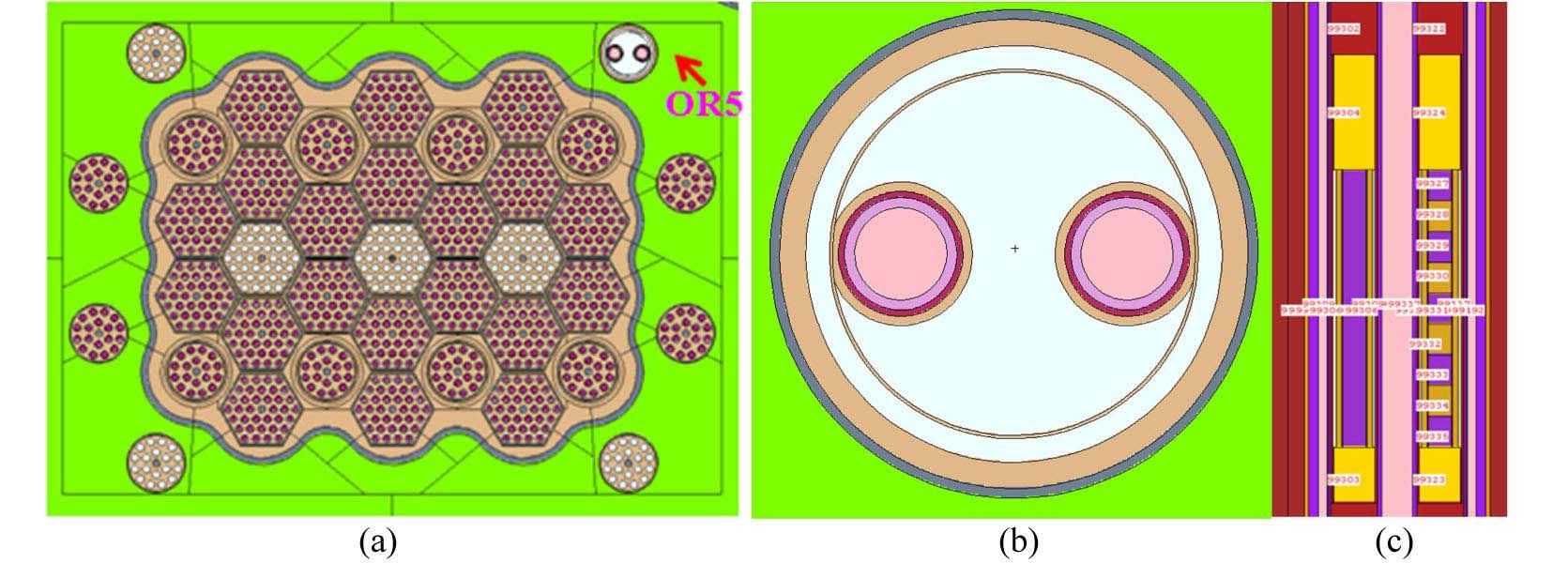
The first irradiation testing of TRISO-coated particle fuel will be carried out in HANARO. An irradiation device, which will contain two separate test rods, is designed for irradiation position and size, irradiation parameters (e.g., temperature and fluence). This device is being irradiated in the OR5 test hole of HANARO core, as shown in Fig. 1. Four OR test holes including OR5 have a nominal fast neutron flux of 1.2-1.5 x 10¹³ n/cm2-s and a thermal neutron flux of 2.0-2.5 x 10¹⁴ n/cm2-s [1].
The irradiation test of coated particle fuel in HANARO is performed with only passive temperature control and the experimental results will be determined after the irradiation by examination in a hot cell. That is, this irradiation testing will not be irradiated in an inert sweep gas atmosphere with individual on-line temperature monitoring and the control of each test rod. However, the irradiation tests, HFREU1 in HFR (High Flux reactor), Petten, Netherlands and AGR (Advanced Gas Reactor) in ATR (Advanced Test Reactor fuel development and qualification program), Idaho, USA, were both performed with on-line active temperature
control and fission product monitoring of the effluent gas, and post-irradiation tests are being carried out [2-31].
This paper describes the design and fabrication of an irradiation device for the irradiation testing of coated particle fuel in HANARO, and discusses the analytical results for the irradiation testing of coated particle fuel.
2. TEMPERATURE EVALUATION OF SPECIMENS
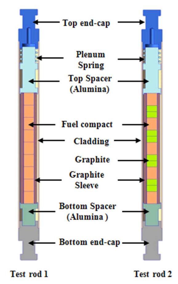
There are two kinds of test fuel rods in the irradiation device as shown in Fig. 2: test rod 1 has nine compacts, and test rod 2 has five compacts and eight graphite specimens. Each compact is a right cylindrical fuel compact nominally 8 mm in diameter, and 10 mm long, and graphite is nominally 8 mm in diameter and 5 mm long. These are loaded in graphite sleeves, which are nominally 8.6 mm in inner diameter and 90 mm long. Two cladding tubes are approximately 16 mm in diameter and 150 mm in height including the plenum space. For this irradiation testing two different types of graphite (matrix graphite for compact and structural graphite for VHTR) are contained to study the impact of graphite fabrication processing variables of graphite performance. Two graphite specimens are arranged between the fuel compacts in test fuel rod 2, as shown in Fig. 2. Table 1 presents the general specifications of the fuel compacts and graphite specimens that are being irradiated at HANARO.
A neutronic analysis was carried out to calculate the heat generation for a temperature evaluation of the test rods including the specimens, to design in detail the irradiation device, and to review the safety of the irradiation. The heat generation rate of TRISO-coated particle fuel and the gamma heat of the materials of the device were also obtained from a neutronic analysis. The model used for the neutronic analysis is shown Fig. 1. Assuming that central position of fuel compact, in which the number of coated particle fuel is 263, is axially located at 5 cm below
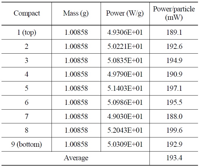
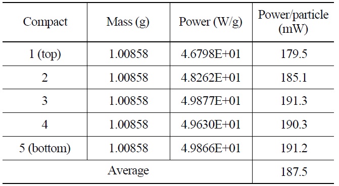
central position of HANARO fuel, calculated power a particle in fuel compact and calculated gamma heat of specimens and parts in rod 1 and rod 2 at MOC (Middle of Cycle) of equilibrium core of HANARO are listed in Table 2 and 3, and Table 4 and 5, respectively. As shown in Table 2 and 3, power per particle is in the range of 188.0 mW to 199.6 mW (average; 193.4 mW) in rod 1, 179.5 mW to 191.3 mW (average; 187.55 mW) in rod 2.
2.2 Temperature Calculation for Irradiation Sesting
Binary mixture of helium and neon, or helium and argon is actually vastly used to control temperature of specimen during irradiation testing of nuclear fuel in research reactor. For example, during irradiation testing of HFREU1/HFR-EU1bis in HFR and AGRs in ATR, temperatures were controlled with on-line monitoring by using mixtures of helium gas and neon gas [2-31]. Generally, thermal conductivity of helium gas is about three times that of neon gas, and about eight times that of argon gas at room
[Table 1.] Characteristics of Coated Particle Fuel and Graphite
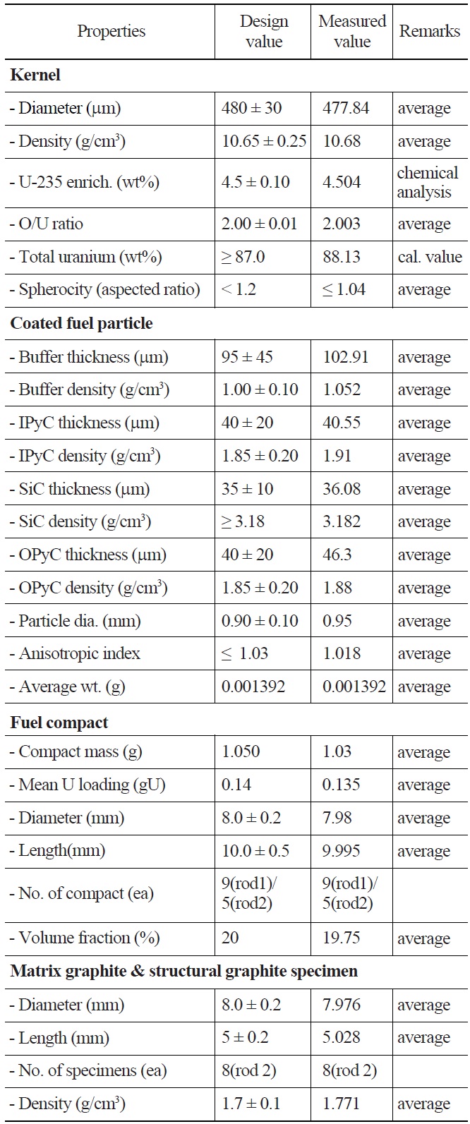
Characteristics of Coated Particle Fuel and Graphite
temperature. And thermal conductivity of these gases increases as temperature rises. But, at HANARO, argon gas use is restrained as far as possible because the release
[Table 2.] Power Per Particle of 9 Compacts in Rod 1

Power Per Particle of 9 Compacts in Rod 1
[Table 3.] Power Per Particle of 5 Compacts in Rod 2

Power Per Particle of 5 Compacts in Rod 2
of radio-activated argon-40 from test atmosphere to coolant during irradiation testing has a decisive effect on HANARO operation. As shown in Fig. 2, rod 1 contains nine fuel compacts, and rod 2 has five fuel compacts and eight graphite specimens. Two graphite specimens are between fuel compacts. To elevate the temperature of fuel compact above 1,000 ℃ at the beginning of the irradiation test, rod 1 is filled up with a mixed gas of 30 % He and 70% Ne. And, to increase temperature of graphite specimens at the beginning of irradiation test, rod 2 is filled up with a mixed gas of 10% He and 90% Ne.
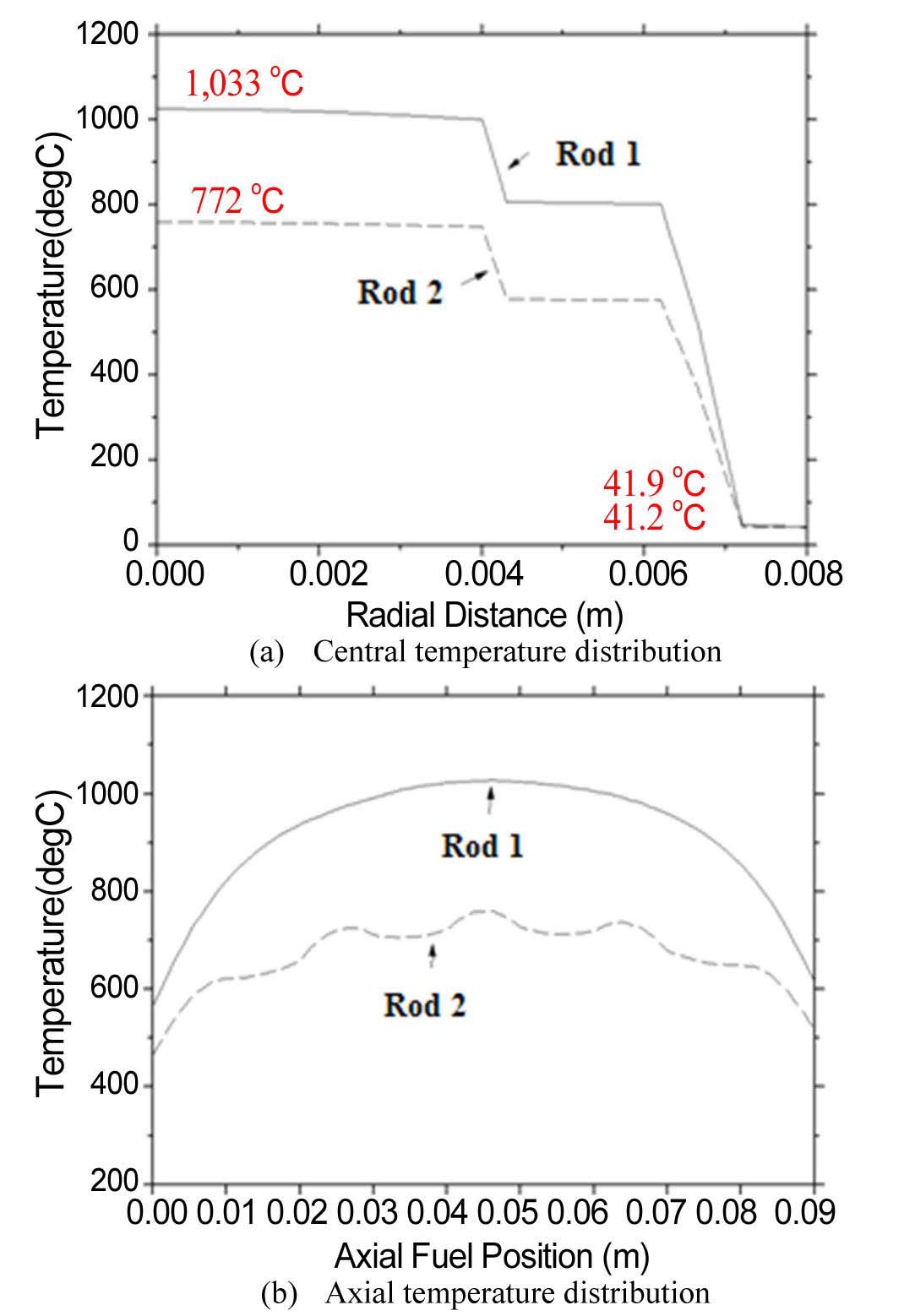
Temperatures were evaluated using COMSOL 4.3a [32]. During the BOC of the irradiation testing, the peak temperature of the fuel compact, which is axially located at the middle of test rod 1, is calculated to be about 1033 ℃ under the condition of a mixed gas of 30% He and 70% Ne, and the peak temperature in test rod 2 is about 772 ℃ under the condition of a mixed gas of 10% He and 90% Ne. The peak temperatures of the graphite sleeves in test rods 1 and 2 are estimated to about 800 ℃ and 580 ℃, respectively. The temperature distribution of these test rods are radially and vertically calculated as shown in Fig. 3.
[Table 4.] Gamma Heat of Rod 1 Table 5. Gamma Heat of Rod 2
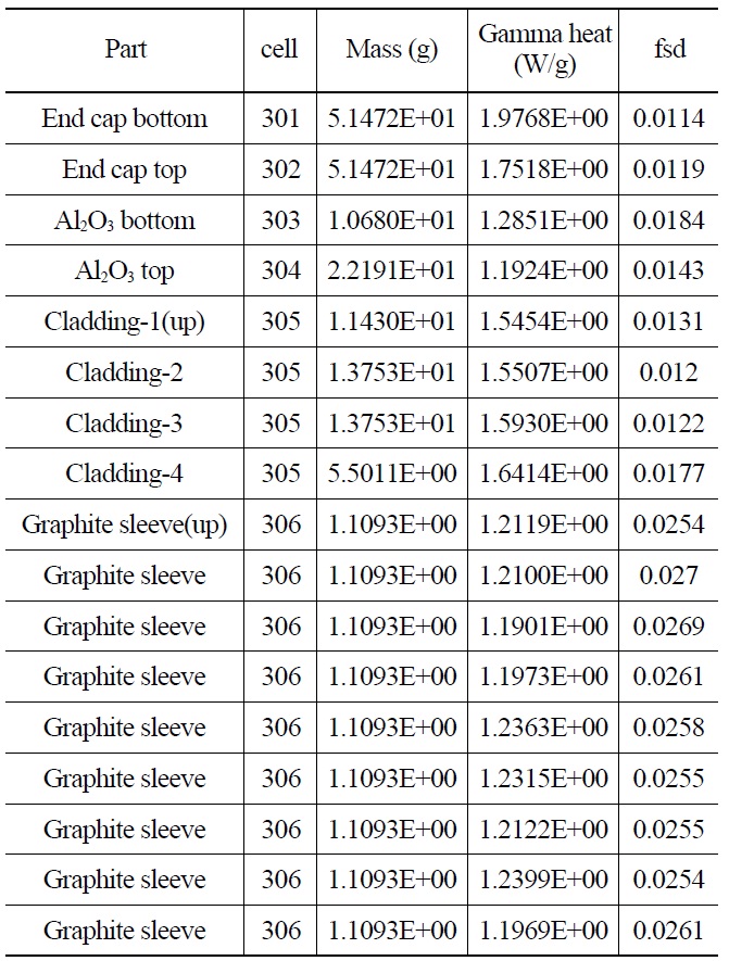
Gamma Heat of Rod 1 Table 5. Gamma Heat of Rod 2
[Table 5.] Gamma Heat of Rod 2
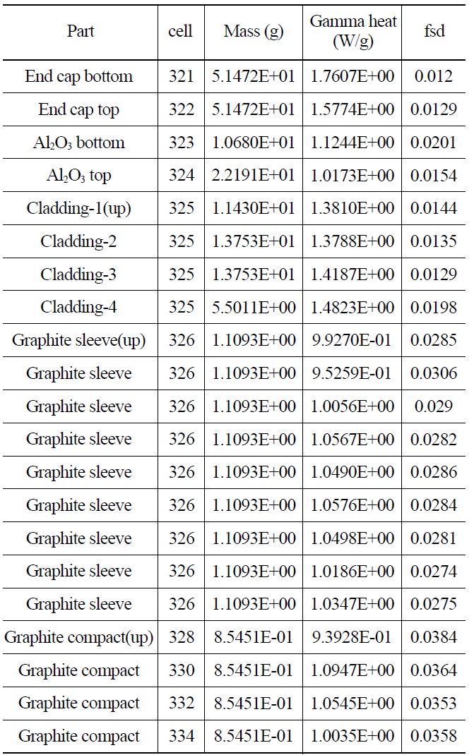
Gamma Heat of Rod 2
3. IRRADIATION SPECIMENS AND TEST RODS
3.1 Fuel Particles and Compacts
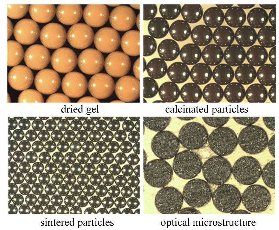
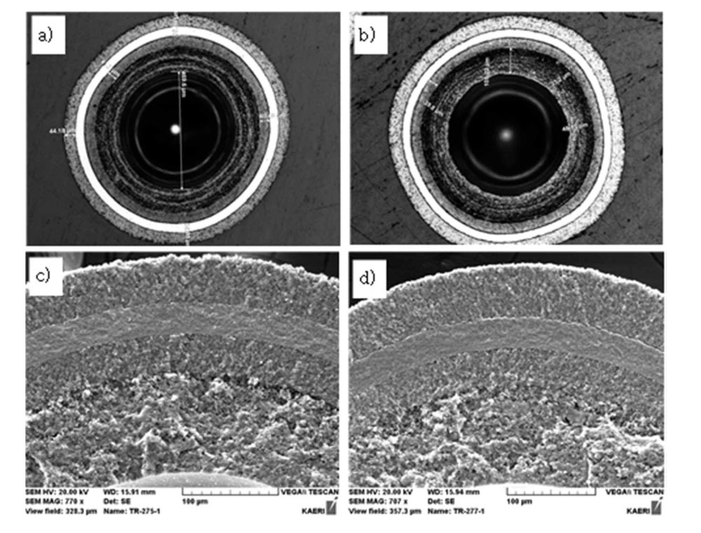
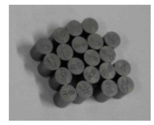
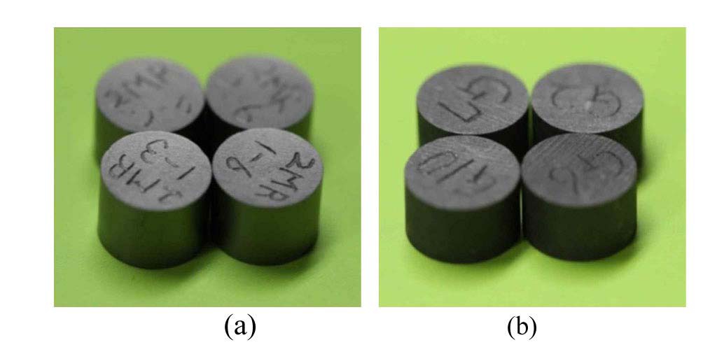
The fuel is comprised of 480 µm diameter LEU (Low Enriched Uranium) fuel kernels (with an enrichment of 4.5 wt% U-235), coated with TRISO coatings (i.e., a buffer layer, a layer of silicon carbide sandwiched between two pyrolytic carbon layers, IPyC, and OPyC) to make up the 900 µm nominal diameter TRISO-coated fuel particles. Fig. 4 shows typical photographs of dried gels, calcinated particles, sintered kernels, and optical microstructures of the kernels. Fig. 5 a) and 5 b) show cross-sections of TRISO fuel, and Fig. 5 c) and d) show SEM micrographs of the coating layers. Next, the fuel particles are over-coated with a thermo-set resin and pressed into fuel compacts that are then sintered to remove the volatile compounds in the resin. Each compact contains approximately 260 fuel particles with a mean uranium content of approximately 0.14 grams. Fig. 6 shows images of the fuel compacts
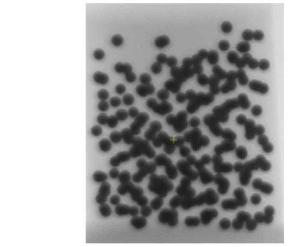
heat-treated at 1800 ℃. As shown in Fig. 6, the particles were pressed into right cylindrical compacts that were nominally 10 mm in length and 8 mm in diameter. The compacts are well-formed, with no apparent cracks or chips. In addition, the X-ray radiograph in Fig. 7 shows that the driver-fuel particles were distributed throughout the compact.
There are two kinds of graphite specimens: one is matrix graphite of a fuel compact, and the other is the structural graphite used in a VHTR. Graphite specimens have a right cylindrical shape that is nominally 5 mm in length and 8 mm in diameter. Fig. 8 shows photographs of the graphite specimens: matrix graphite and structural graphite. Matrix graphite and structural graphite specimens are located between the fuel compacts in test rod 2.
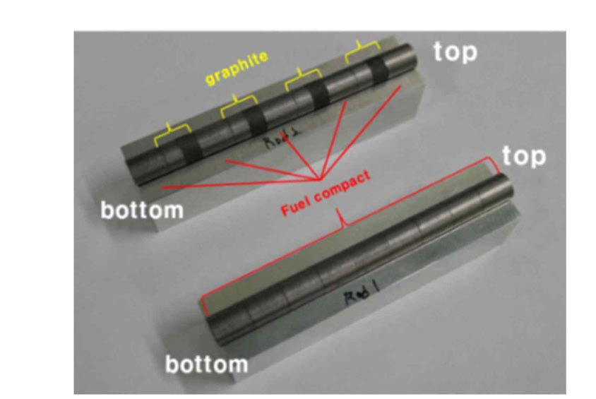
Fig. 9 shows photographs of the fuel compacts and graphite specimens for rods 1 and 2 before inserting in the graphite sleeve. These specimens are inserted into test rods 1 and 2, respectively.
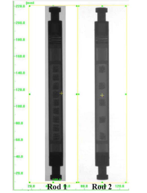
End-plugs of the test rods were welded by TIG welding, and using X-ray radiography, it was then verified that the internal layouts of the fuel compacts, graphite specimens, and other parts had no problems. Fig. 10 shows X-ray images of the assembled test fuel rods 1 and 2 before welding pin holes onto the end-plug of the test rods. In addition, after injecting mixed gas through the pin hole at the end-plug of test rods 1 and 2, pin holes were welded using laser welding. The integrity of the welded parts, end-plugs, and pin hole, was confirmed through PT (Penetration Test) test and He-leak test.
Before settling the detailed design of an irradiation device for the irradiation testing of TRISO-coated particle fuel at HANARO, three preliminary devices were designed and fabricated. In addition, out-of-pile testing including a measurement of the pressure drop, vibration, and endurance was performed. The validity of their designs was then confirmed. After approving the final design of the device for irradiation testing of coated particle fuel at HANARO according to the results of out-of-pile testing, the final device excluding the test fuel rods was manufactured. Additionally, the irradiation testing of coated particle fuel using this device was begun from August 2013.
4.1 Design and Fabrication of Mock-up Device
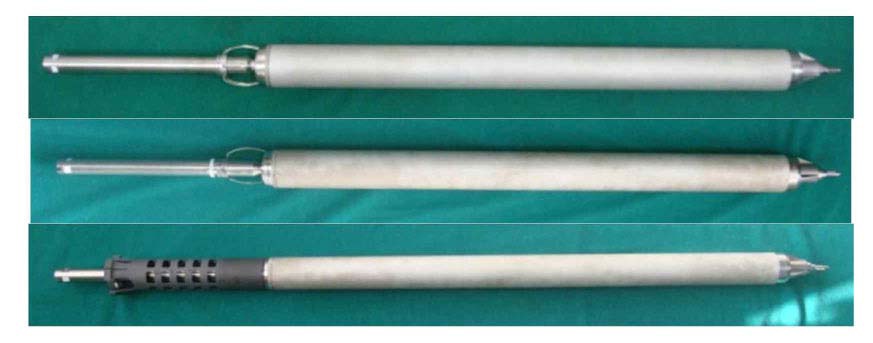
There were three kinds of mock-up irradiation devices, a 6-spring type, 3-spring type, and plug type, for coated particle fuel irradiation testing which consists of the bottom guide structure, the main body, and the top guide tube. The rod tip of the bottom guide structure is assembled with a receptacle in the reactor core, and the main body is a major part of the capsule in which the test rods are installed, and it includes an external tube of a cylindrical shell with a 56 mm external diameter, 2.0 mm thickness, and about 1,000 mm length. These designs were based on an instrumented capsule for nuclear fuel irradiation testing [33,34]. These devices have no central rod. The central rod is made with Zircaloy-4, which is generally an expensive material. No central rod is able to reduce manufacturing costs, and to increase space to install specimens. That is, there is a distinct difference between these devices and former devices for nuclear fuel irradiation testing. OR5 test hole (or flow tube) is embedded within the compass of the reflector tank, 2 m diameter and 1.2 m high Zircaloy-4 tank containing D2O. This test hole is made of Zircaloy-4, about 1.2 m high and 1 mm thick. Both ends of the tube are welded to top and bottom plates about 20 mm thick. The present design of non-instrumented irradiation devices for nuclear fuels, based on one of HANARO fuel assemblies, 18-element fuel assembly in circular array, have springs (3 or 6 spring made of Inconel or stainless steel) in the top of the devices. During irradiation duration using these devices, it is able to form the wear inside the test tube of continuously vibrating the springs due to flow-induced vibration. The issue that accumulated wear inside the test hole was able to influence on the integrity of the tube was consistently brought up. If D2O is leaked from the reflector tank to coolant by occasion of damage of the test tube, the leakage of D2O makes it difficult to continuously operate HANARO. In order to exclude the wear inside the test tube, the plug type design is adopted. The hardness of Zircaloy-4 is higher than that of Al 6061. Generally, in case of metallic material the harder the less wear. The plug, Al 6061 alloy, is contacted to the top plate, Zircaloy-4, of the reflector tank during irradiation duration. Therefore, there is no possibility to occur wear inside the test tube if the plug type device is used in irradiation testing of nuclear fuel. Three kinds of mockup devices on the basis of assembly drawings were prepared, as shown in Fig. 11.
4.2 Out-of-pile Testing using Mock-up Device
A. Pressure drop
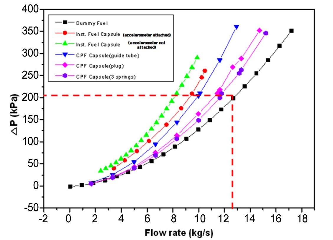
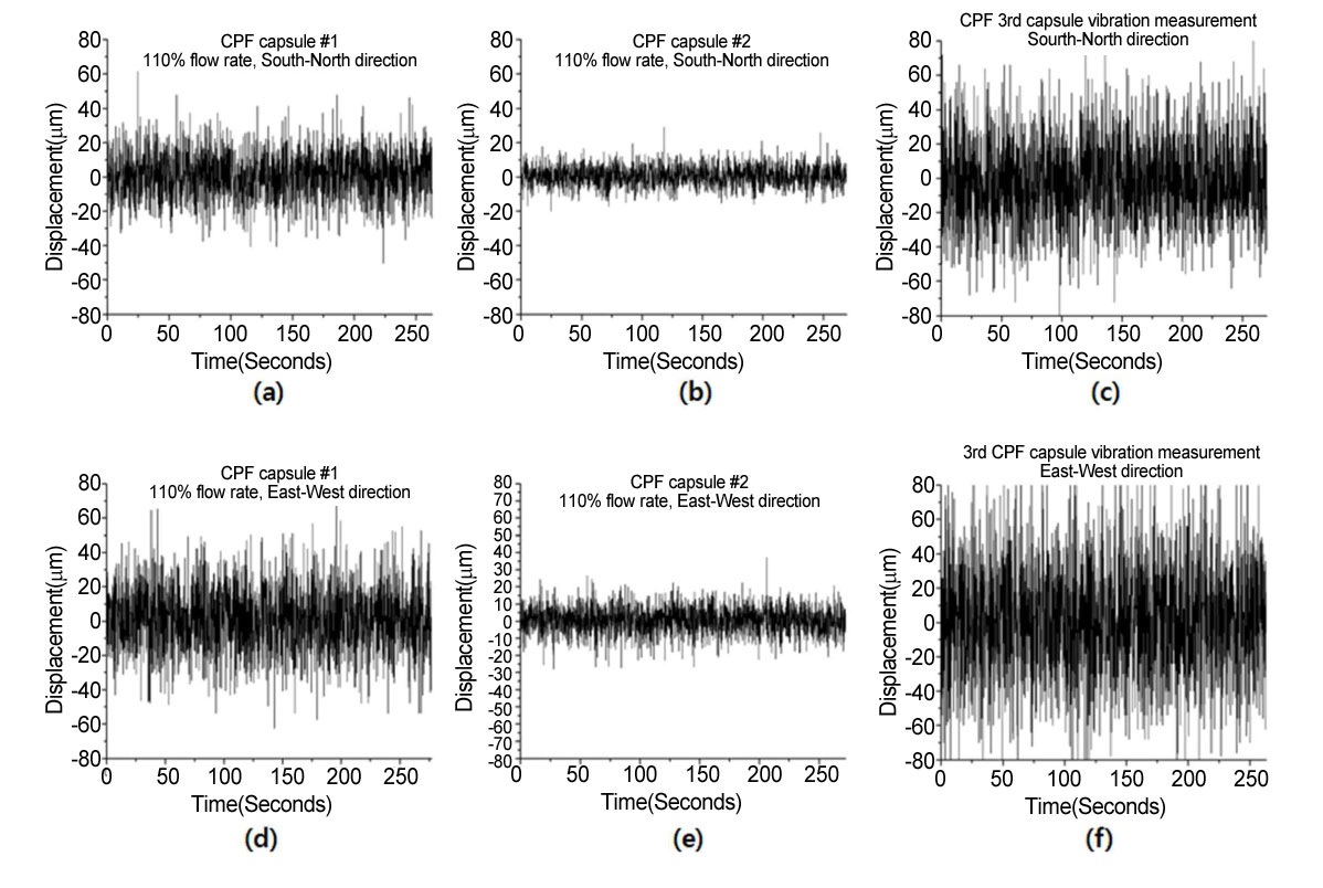
Out-of-pile tests including the measurement of the pressure drop and vibration, and an endurance test, were carried out using three mockup devices, as shown in Fig. 11. Compatibility with the test hole and requirements, such as the pressure drop (>200 kPa at 12.7 kg/sec of rated flow; see Fig. 12) and vibration (less than 300 µm at 110% of rated flow; see Fig. 13 and Table 6) were verified. As shown in Fig. 12, a pressure drop of the 6-spring type was 210 kPa at 12.7 kg/sec of rated flow; that of the 3-spring type, 209.4 kPa at 11.78 kg/s; and that of the plug type, 209.7 kPa at 11.45 kg/s.
B. Vibration displacement
Fig. 13 shows that the vibration displacement of the plug type was smallest; and that of the 3-spring type, the largest. In Table 6, the vibration displacement appeared qualitatively smaller in the order of plug type, 6-spring type, and 3-spring type. The maximum vibration displacements of the 6-spring type, plug type were 68 µm, 37.2 µm, and 126 µm, respectively. These are smaller than the 90 µm of the 18-element fuel assembly of a HANARO drive fuel [36]. However, the maximum vibration displacement of the 3-spring type was 126 µm. In addition, the RMS of the three types was 3.29 to 33.4 µm. These appeared to be smaller than the 19 to 43 µm of the 18-element fuel assembly of the HANARO drive fuel [36].
C. Endurance test
Endurance tests for each type of mock-up irradiation device were carried out for about 14 days, respectively. There was no significant evidence of any wear on all parts
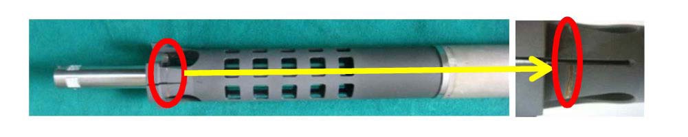
of the three types of mock-up irradiation devices. And then, an endurance test of the plug type device was also performed for about 143 days under the condition of a 110% rated flow of 12.7 kg/s. There was no significant evidence of any wear, with the exception of the top plug as shown in Fig. 14. The maximum width of wear is 1.3 mm, and the maximum depth is 0.06 mm.
4.3 Irradiation Device Preparation for Irradiation Testing
According to the results of out-of-pile tests described in section 4.2, the pressure drop of the plug type is the highest under the same coolant flow rate as shown in Fig. 13, and the vibration displacement is the smallest under the same coolant flow rate as listed in Table 6. And, no significant wear was apparent, with the exception of the top plug after endurance test under 110% of rated coolant flow for 143 days, as described above. Therefore, the plug type device was selected as the most promising design compared with 3-spring and 6-spring types for loading in an OR test hole of HANARO. A final detailed drawing of the plug type device was accepted, as shown in Fig. 15, and the components of the device, except the test rods, were fabricated
[Table 6.] Vibration Displacements of Maximum, Minimum and RMS [35]. (unit: μm)
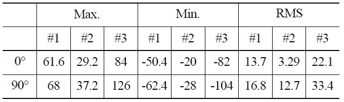
Vibration Displacements of Maximum, Minimum and RMS [35]. (unit: μm)
to load in the test hole, OR, of HANARO, as shown in Fig. 16.
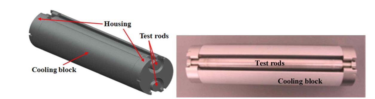
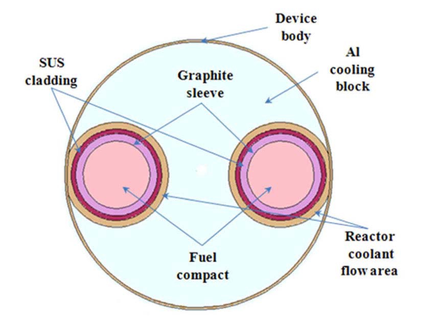
The device for irradiation testing consists of two separate test rods vertically centered in the HANARO core. One has nine compacts, and the other has five compacts and eight graphite specimens. A three-dimensional view and photograph of the sub-assembly for the test rods are shown in Fig. 17. A cooling block surrounds and separates the two test rods in the irradiation device. In addition, Fig. 18 shows a cross section of the irradiation device including two test rods.
This device, including the two test rods, is being loaded and irradiated at the test hole on August 2013 at HANARO. The device will then be operating for about 150 effective full-power days. The peak temperature of about 1030℃ will be achieved in BOC of the irradiation testing. After a peak burn-up of about 4 at% (atomic percentage) and a peak fast neutron fluence of about 1.7×10²¹ n/cm2, a PIE of the irradiated coated particle fuel will be performed at IMEF.
5. SAFETY ANALYSIS FOR IRRADIATION TESTING
Before performing the irradiation testing of the device for coated particle fuel, the safety analysis was carried out to make sure of the compatibility with the test hole of HANARO and the irradiation performance of coated particle fuel. The following are required items for a safety review;
-Hydraulic compatibilities with HANARO core; pressure drop (>200 kPa at rated coolant flow), vibration (<300 µm of vibration displacement), and endurance.
-Maximum surface temperature of test rod and maximum temperature of fuel compact under the hypothetical accidents.
-Reactivity effect from loading the irradiation device into the test hole.
The ONB (onset of nucleate boiling) and DNB (Departure from nucleate boiling) on the surface of the test rod must also be evaluated.
According to the results of a safety review for irradiation testing [38], it complies the design criteria of the test rod, and the criteria of an accident analysis of HANARO.
As outlined in this paper, KAERI has a plan to perform the first irradiation testing of coated particle fuel at HANARO to support the development of a VHTR in Korea. This testing will be carried out to demonstrate and qualify TRISO-coated particle fuel for use in a VHTR. The objectives of this irradiation testing are to provide data supporting the development of an understanding of the relationship between fuel fabrication processes, fuel product properties, and irradiation performance, and to prepare specimens for heat-up testing under accident conditions. During 2012, a mock-up irradiation device was prepared to carry out an out-ofpile test, and the test was performed. At the beginning of 2013, the final design of the irradiation device was accepted and the device was fabricated.
The irradiation device contains two test rods, one has nine fuel compacts, and the other has five compacts and eight graphite specimens. The fuel compacts will be irradiated in an inert gas atmosphere without on-line temperature monitoring and control combined with on-line fission product monitoring of the sweep gas. The irradiation device is being loaded and irradiated into the test hole OR5 in the HANARO core from August 2013. In addition, after a peak burn-up of about 4 at% and a peak fast neutron fluence of about 1.7×10²¹ n/cm2, a PIE of irradiated coated particle fuel will be performed.
Before performing the irradiation testing of the device for coated particle fuel, the safety analysis was carried out to make sure of irradiation performance of coated particle fuel. The following conclusion was made: the irradiation device for coated particle fuel has the compatibility with the HANARO core during irradiation testing. According to a performance review of the test rods, the design criteria of the test rod, and the criteria of the accident analysis of HANARO, are in compliance.


![Mockup Devices (from Top; 6-spring, 3-spring, and Plug Type) [35].](http://oak.go.kr/repository/journal/12953/OJRHBJ_2013_v45n7_941_f011.jpg)
![Effect of Pressure Drop on the Flow Rate [35].](http://oak.go.kr/repository/journal/12953/OJRHBJ_2013_v45n7_941_f012.jpg)
![Effect of Vibration Displacement on the Measured Directions 0° (a; 6-spring Type, b; 3-spring Type, c; Plug Type) and 90° (d; 6-spring Type, e; 3-spring Type, f; Plug Type) [35].](http://oak.go.kr/repository/journal/12953/OJRHBJ_2013_v45n7_941_f013.jpg)
![Vibration Displacements of Maximum, Minimum and RMS [35]. (unit: μm)](http://oak.go.kr/repository/journal/12953/OJRHBJ_2013_v45n7_941_T006.jpg)
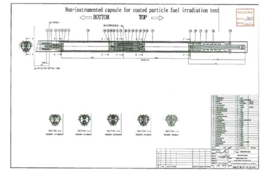
![Accepted Assembly drawing of Irradiation Device forIrradiation Testing of Coated Particle Fuel [37].](http://oak.go.kr/repository/journal/12953/OJRHBJ_2013_v45n7_941_f015.jpg)
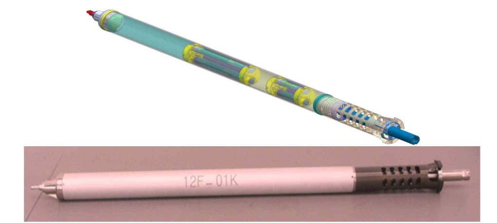
![Irradiation Device for Irradiation of TRISO-coatedParticle Fuel in HANARO [37].](http://oak.go.kr/repository/journal/12953/OJRHBJ_2013_v45n7_941_f016.jpg)