A full-sized model for the horizontally oriented metal cask containing 21 spent fuel assemblies has been considered to evaluate the internal natural convection behavior within a dry shield canister (DSC) filled with helium as a working fluid. A variety of two-dimensional CFD numerical investigations using a turbulent model have been performed to evaluate the heat transfer characteristics and the velocity distribution of natural convection inside the canister. The present numerical solutions for a range of Rayleigh number values (3×10⁶~3×10⁷) and a working fluid of air are further validated by comparing with the experimental data from previous work, and they agreed well with the experimental results. The predicted temperature field has indicated that the peak temperature is located in the second basket from the top along the vertical center line by effects of the natural convection. As the Rayleigh number increases, the convective heat transfer is dominant and the heat transfer due to the local circulation becomes stronger. The heat transfer characteristics show that the Nusselt numbers corresponding to 1.5×10⁶ < Ra < 1.0×10⁷ are proportional to 0.5 power of the Rayleigh number, while the Nusselt numbers for 1.0×10⁷ < Ra < 8.0×10⁷ are proportional to 0.27 power of the Rayleigh number. These results agreed well with the trends of the experimental data for Ra>1.0×10⁷.
A large increase in the number of casks for transport and/or storage of spent nuclear fuel is predicted in the future. The principal demand for storage or dual purpose (transport /storage) casks for interim storage of spent nuclear fuel prior to reprocess or permanent disposal is expected to be increased. The demand for an increase of interim storage is expected for both on-site and off-site storage facilities. Dedicated transport casks can also be used to transport fuels from spent fuel pools in the nuclear power plants to off-site interim storage, reprocessing, and final disposal sites.
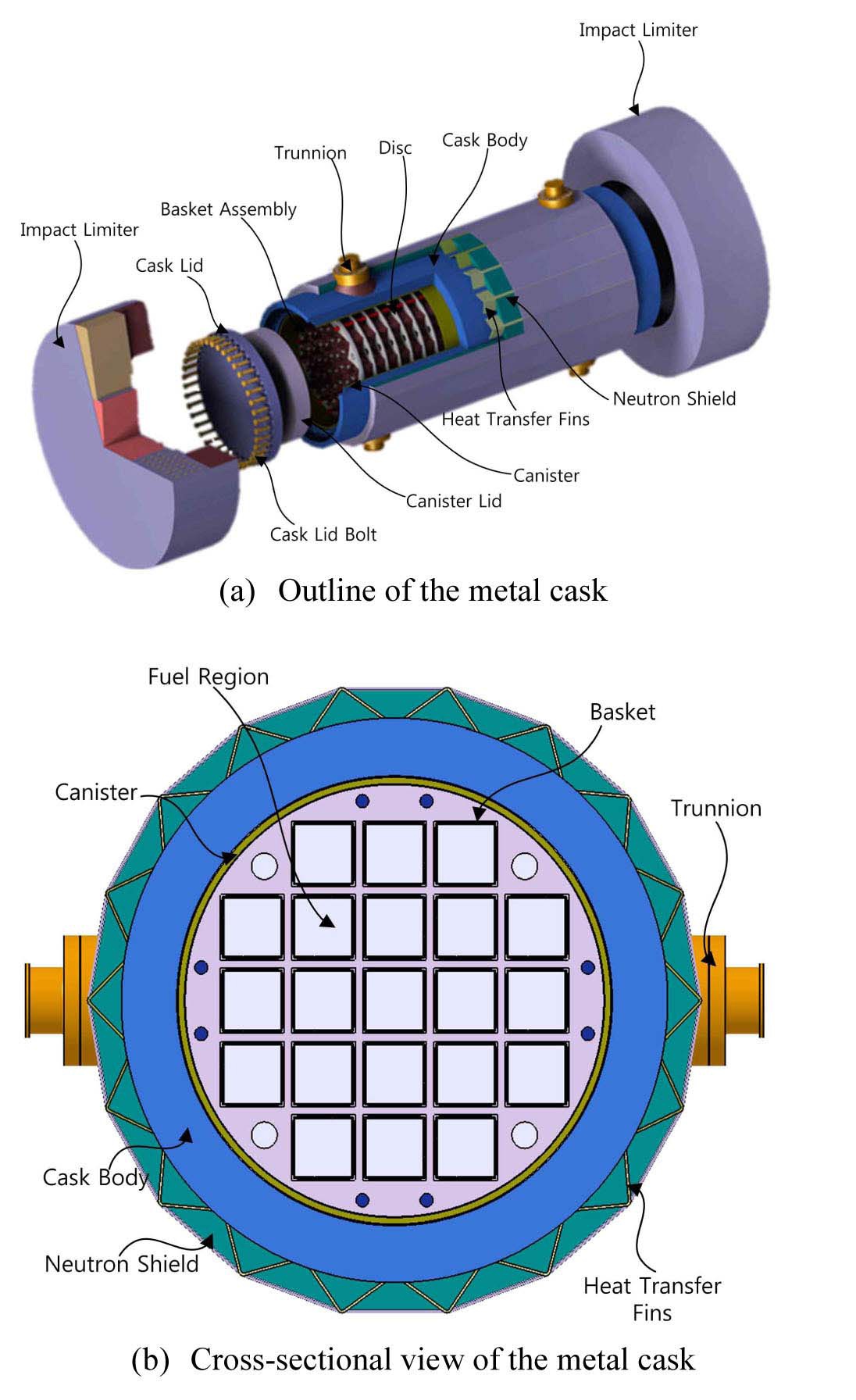
For the purpose of interim storage, a dual purpose metal cask containing 21 spent fuel assemblies is under development by Korea Radioactive Waste Management Corporation (KRMC) in Korea. The major components of this cask consist of a main body made of carbon steel, a stainless steel dry shielded canister (DSC) and stainless steel baskets to contain the spent fuel assemblies as shown in Fig. 1.
Since this dual purpose cask is used for transport and storage of the spent fuel assemblies, it essentially will be faced with the transport process, including installation on the transport vehicle. During this process, the decay heat generated in the metal cask is removed by conduction, convection and radiation heat transfer. It is well known that the natural convection heat transfer by buoyance driven helium flow within the canister of the cask is a significant heat transfer mechanism when the cask is transported in a horizontal orientation. Special attention is therefore paid to natural convection heat transfer inside the DSC.
A large number of studies on natural convection heat transfer have been performed for simple geometries, both experimentally and numerically.
A good example of the early studies on concentric and eccentric annuli can be found in the papers of Kuehn and Goldstein, in which they employed air and water inside an enclosure formed by two copper-made concentric horizontal cylinders for the experimental procedure and used a finite difference method for the numerical counterpart [1,2]. The Rayleigh number, based on the gap width, ranged from 2.11×10⁴ to 9.76×10⁵ and the authors found the fluid to behave in an unsteady pattern for Rayleigh number values higher than 1.0×10⁵ [1]. They also presented heat transfer results of the concentric geometry for Rayleigh numbers from 2.2×10² to 7.7×10⁷ which includes regions of conduction, laminar convection, and partially turbulent convection. Their results showed that the Rayleigh number based on the gap-width was about 106 for the turbulence transition. The annulus internal flow was characterized by a turbulent upward moving plum above the inner cylinder and a turbulent downward flow against the outer wall for Rayleigh number higher than the transition value [2]. Macleod and Bishop also performed experimental work and presented several measurements of overall heat transfer rates and profiles of the time-averaged and fluctuations of the temperature field for fully turbulent natural convection [3]. Furthermore, they presented an empirical equation which
correlates the heat transfer data that takes into account the Rayleigh number in the range of 2.2×10² to 7.7×10⁷. Their results indicated that the expansion number (β∆T) should be taken into account, regardless of the Rayleigh number, when predicting the heat transfer rates [3]. The work by Char and Hsu, on turbulence modeling of natural convection in cylindrical horizontal annuli, proposed a comparison of the different turbulence models, suggesting a better modeling practice [4].
Some studies on natural convection heat transfer in an enclosure with more complicated geometry, such as enclosed horizontal rod bundles, have been reported.
Canaan and Klein presented that natural convection heat transfer was experimentally investigated in an enclosed horizontal rod bundle, which characterizes a spent fuel assembly during the transport and some dry storage scenarios. The convective heat transfer correlations had been modified for radiation heat transfer using a numerical technique. They also suggested the conduction and convection regimes, distinguished by a critical Rayleigh number and the convection flow regime was turbulent flow condition [5]. Keyhani and Luo numerically investigated natural convection heat transfer in enclosed horizontal 4×4 arrays of heated rods with constant heat flux dissipation. The results indicated the enclosure Nusselt number increased as the order of the array N was increased from 3 to 9 and the reported correlations could be readily used to estimate the maximum temperatures in the arrays with the order from 3 to 9 [6].
However, most studies were focused on the natural convection within the spent fuel assemblies. Only a few studies have been performed on the natural convection heat transfer in an enclosure with many inner rectangular tubes such as DSC in a spent fuel transport cask.
Nishimura et al. conducted a heat transfer and flow visualization experiment on a one-fifth scale model to simulate a DSC with 24 PWR spent fuel assemblies, then the results of the thermal and fluid flow analysis were compared with the measurements. Their results indicated that the overall heat transfer coefficients were proportional to about a 0.27 power of the Rayleigh number when air is used as a working fluid [7]. Xie et al. performed a numerical investigation on natural convection heat transfer in a horizontally oriented dry storage system to store 24 spent fuel assemblies. The numerical predictions using commercial CFD codes were compared with the experimental data and heat transfer correlations were presented on three regimes of Rayleigh number [8].
The above-mentioned work was conducted for a scale model of actual dry storage containing 24 fuel assemblies with air as working fluid. However, the results of natural convection heat transfer for a scale model has not been compared with the actual dry storage using a numerical approach or other methods.
In our study, a full-sized metal cask model containing 21 spent fuel assemblies is considered as the numerical model to evaluate the internal natural convection behavior within the DSC with helium as a working fluid. A variety of two-dimensional models are also employed to calculate the heat transfer correlations for helium. In this case, the Rayleigh numbers are estimated from approximately 6×10⁶ to 1×10⁷ within the canister cavity filled with helium. According to this range of Rayleigh numbers, the two-dimensional CFD models are applied to the turbulent flow model since the transition Rayleigh number for turbulence is about 106 using the results of Kuehn and Goldstein [1].
2. GOVERNING EQUATIONS AND SOLUTION METHOD
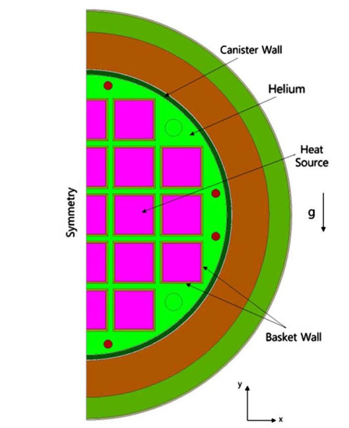
The physical problem, analyzed in the present work, is a full-sized model of the actual cask. The analysis model consists of a fuel basket assembly, canister, cask body and neutron shield layer. The canister cavity is filled with helium as shown in Fig. 2. Fuel baskets containing 21 fuel assemblies have a square cross sectional shape, 241mm in width and 4,395mm in length. The width of the gap between the baskets is 36mm, which forms a path for natural convection flow. The canister is a cylinder with an inner diameter of 1,636mm, 50mm in thickness and 4880mm in axial length. The cask body and neutron shield layer have 215mm and 104mm in thickness, respectively.
A two-dimensional thermal and fluid flow analysis is performed to evaluate the effect of the natural convection within the canister. Considering the symmetric nature of the problem, a half cask is adopted as a computational domain given in Fig. 2. The problem is described with the following RANS (Reynolds Averaged Navier-Stokes) conservation equations. Additionally, the averaged energy equation of the turbulent incompressible steady flows is included.
Continuity;
Momentum;
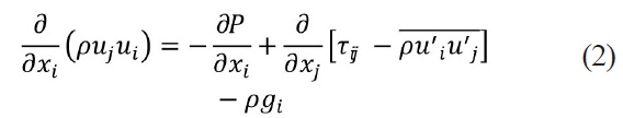
Energy;
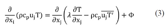
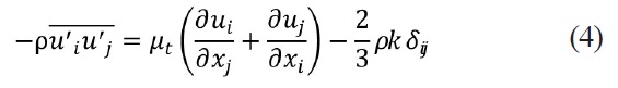
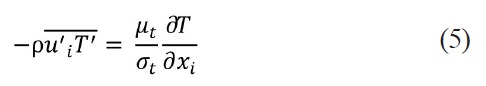
The above equations contain respectively the Reynolds stress terms and other correlations of the fluctuating scalar and velocity which require a closure. The one point closure models are generally based on the concept of PrandtlKolmogorov’s turbulent viscosity which is applied in its high Reynolds number form. Thus, the turbulent Reynolds stress tensor and the correlation of the fluctuating value of temperature and velocity component are deduced by the following algebraic relations:
A number of different turbulence models can be applied when solving turbulent flow fields. The renormalization group (RNG) k-ε model was selected for this analysis. RNG k-ε turbulent model was derived using a statistical technique called renormalization group theory by Yakhot and Orszag [9]. The primary reasons for using the RNG k-ε turbulent model are that it allows a variation in the turbulent Prandtl number as a function of flow conditions, it provides a way for including low-Reynolds number effects in the effective viscosity formulation, and it includes an extra term, Rε, in the ε-equation to model separated flows better. The conservation equations for the RNG k-ε turbulence model are given below:
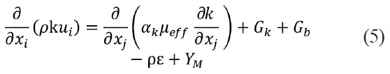
Turbulent kinetic energy (k);
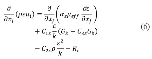
Dissipation of turbulent kinetic energy (ε);
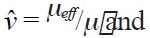
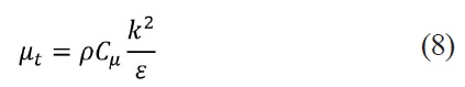
The RNG k-ε turbulent model provides an analytically derived differential formula for the effective viscosity that accounts for low-Reynolds number effects in the flow domain. It is written in terms of the effective viscosity, µeff.
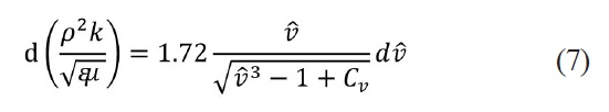
In this equation,
The degree to which ε is affected by buoyancy is determined by the constant C3ε and is calculated according to the following relation:
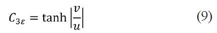
The above value, C3ε=1 for flow direction aligned with gravity and C3ε =0 for flow direction perpendicular to the gravity vector. The various model constants are C1ε =1.42, C2ε =1.68 and Cμ□=0.0845, which were derived exactly in the RNG procedures.
Use of the differential formula for the viscosity requires an appropriate treatment of the near-wall region. Specifically, it requires that the viscous sub-layer and the buffer layer be resolved all the way to the wall. The use of standard wall functions is not appropriate when low-Reynolds number effects are pervasive within the flow domain. Additionally, the standard wall function approach is not applicable in the presence of a strong body force such as in the case of a buoyancy-driven flow. Therefore, the boundary layer must be adequately resolved by the computational grid in order to obtain the correct surface heat transfer rates.
The helium, as working fluid, is considered as incompressible and Newtonian with constant physical properties, except for density variation. To calculate the density variation due to the buoyancy effect, the Boussinesq approximation and incompressible ideal gas law are usually applied.
The density variation via the Boussinesq approximation is caused by the fluid’s thermal expansion, and it is given by:
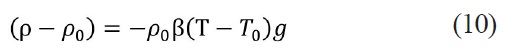
Equation (10) is obtained by using the Boussinesq approximation, ρ=ρ0 (1-β∆T), to eliminate ρ from the buoyancy term. This approximation is valid only when β(T–T0) « 1.
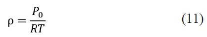
The incompressible-ideal-gas law is applied in the density calculation when pressure variations are small enough such that the overall internal flow conditions are essentially incompressible, but a relationship between density and temperature is required for the driving force for fluid flow. The internal density variation is based on the input operating pressure (P0) and the computed fluid temperature (T), and it is given as follows.
The incompressible-ideal-gas law computes the density internally, while the Boussinesq approximate model treats density as a constant value in all solved equations, except for the buoyancy term in the momentum equation. Therefore, the Boussinesq approximate model should not be used if the temperature differences in the domain are relatively large.
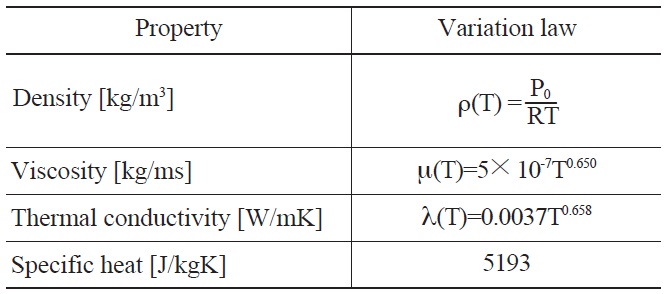
For the above-mentioned reasons, the incompressibleideal-gas law was applied in the density calculation in this study. Other thermal properties are treated as functions of temperature except for specific heat as shown in Table1 [10].
The finite volume method (FVM) is applied to discretize the differential equations of the mathematical model described above, using a segregated implicit solver to solve the resulted algebraic equation system. Equations are linearized and then sequentially solved using the Gauss-Seidel algorithm accelerated by an Algebraic Multigrid method [11]. The pressure-velocity coupling is achieved through the use of the Semi-Implicit Method for Pressure-Linked Equations (SIMPLE) algorithm [12]. Diffusive terms of the equations are discretized using a second-order central scheme, and the convective terms are discretized using a second-order upwind scheme [13].
A body force weighted scheme is chosen in the discretization of pressure to deal with this buoyancy-driven flow [14]. All these numerical procedures were implemented in the unstructured CFD code, Fluent V13.0 [15].
Three main convergence criteria were applied to determine when the numerical procedure described above has made convergence to a solution. The first criterion consists of reaching stable values for the temperature at all the surfaces of the canister and baskets, meaning that a converged steady state has been reached (a variation of less than
[Table 1.] Thermal Properties of Helium

Thermal Properties of Helium
0.5℃ in 1000 iterations is required). The second criterion is the balance between the heat transfer rate from the basket surfaces and that into the internal surface of the canister (a difference of less than 1% is required). The final criterion is to check that the values for the scaled residuals of the equations are below certain magnitudes (10-3 for the mass, momentum and turbulent equation and 10-10 for the energy equation)
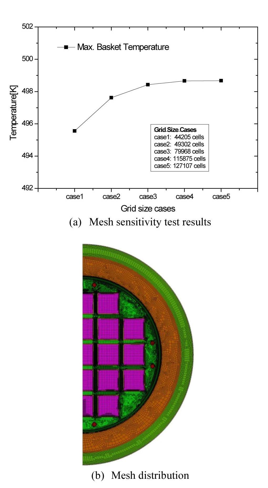
To choose the available grid size of the configuration, five different cases of mesh sizes were tested. The results were almost the same in the two last cases as shown Fig 3(a). From a grid sensitivity study, the grid case 4 was selected to obtain a grid independent solution. The grid case 4 is constructed with approximately 116,000 quadrilateral meshes and a high mesh density in an area of high temperature and velocity gradient. The computational grid arrangement is clarified in Fig. 3(b).
The assumption of symmetry makes it possible to restrict computational domain to half of the cask. No slip condition at the basket wall and inter wall of the canister and no gradient at the symmetric surface are both assumed. A heat source corresponding to the decay heat per assembly is applied to the interior of the basket instead of the constant heat flux at all basket walls. The external surface of the cask takes heat exchange by convection and radiation with an ambient temperature of 38℃. Natural convection heat transfer at the external surface is as follows.
Radiation heat transfer between the external surface and the ambient environment is evaluated in the model by applying an emissivity of 0.4 for the stainless steel surface.
The operating pressure selected for this study is 101.325kPa, a standard atmospheric pressure at sea level to calculate heat transfer coefficients for natural convection. The gauge pressure is specified during solution initialization as 0 Pa for all numerical simulations. The absolute pressure is the operating pressure plus the gauge pressure. Gravity is specified as 9.81m/s2. To achieve lower Rayleigh numbers for a given geometry and temperature difference, the gravity vector is simply scaled below its normal value.
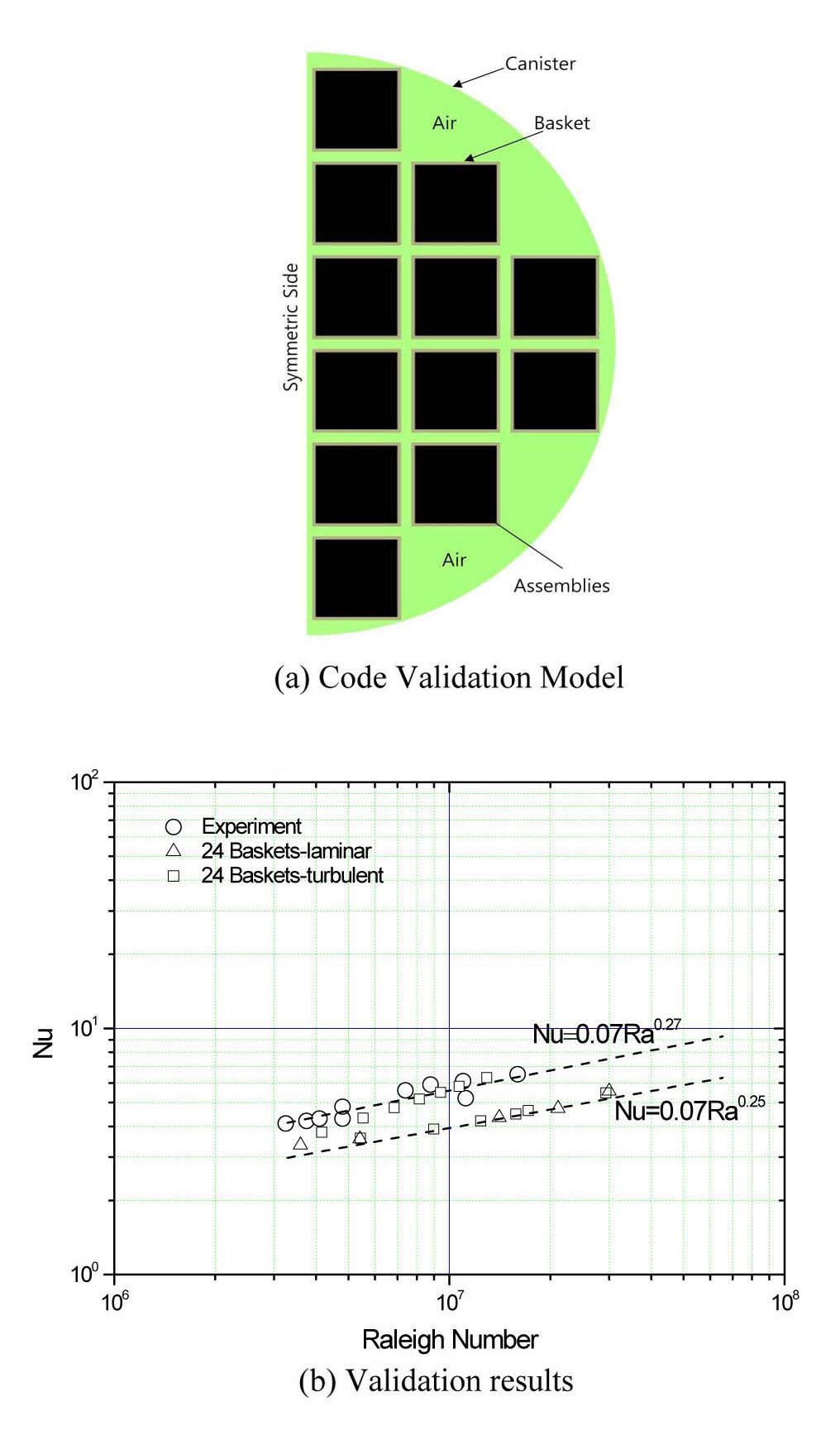
The present numerical solutions for a range of Rayleigh number values (3×10⁶~3×10⁷) and working fluid as air are further validated by comparing with the experiment of Nishimura et al [7]. The experiment of Nishimura et al is a 1/5 scale model of the actual dry storage canister containing 24 baskets. Therefore, the validation model was made with 24 instead of 21 baskets as shown in Fig. 4(a).
Nishimura et al. defined the average heat transfer coefficient as follows;
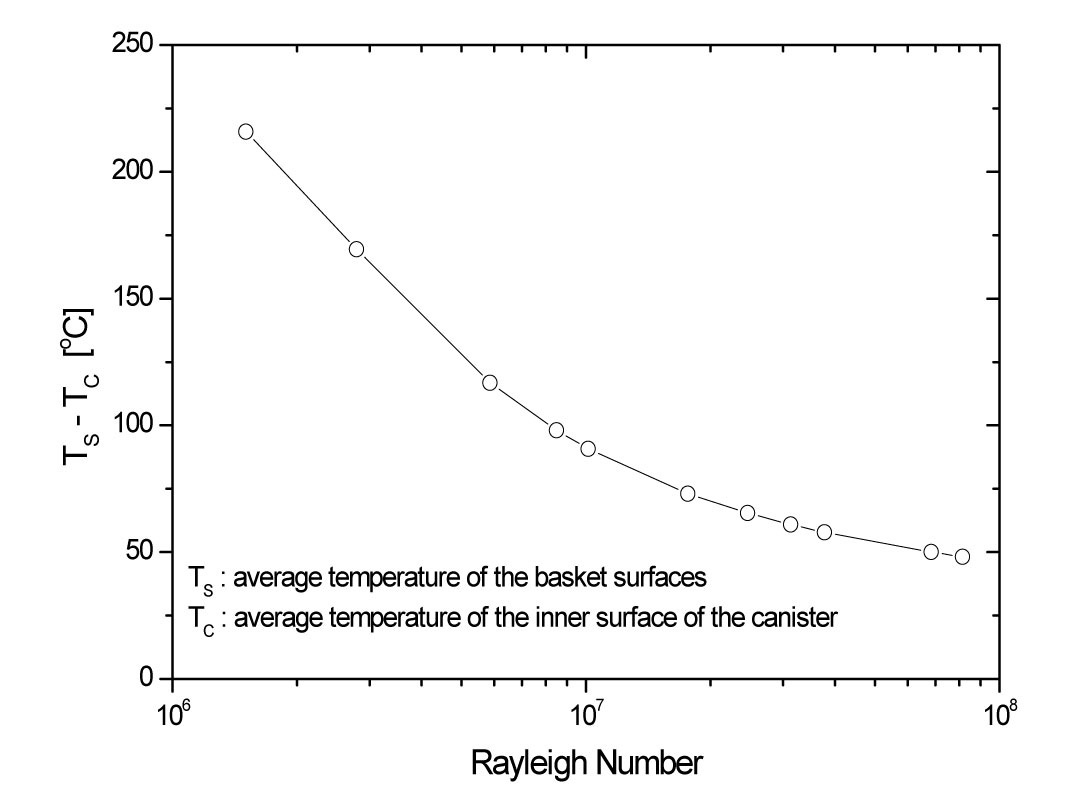
In the above equation, qs means the heat flux on the basket surfaces specified by Qconv /Abasket. The convective heat Qconv represents a net heat flow by convection on the basket walls, Abasket is the total area of the basket side walls, TS is the average temperature of the basket surfaces along the gap in the vertical centerline of the canister, and TC is the average temperature of the inner surface of the canister.
The average Nusselt number is then defined as
In the above equation, λ is the thermal conductivity of the enclosed air and RC is the inner radius of the canister.
The Rayleigh number is defined as
The experimental result shown in Fig. 4(b) implies that the heat transfer coefficients are proportional to about a 0.27 power of the Rayleigh numbers when air is used as the working fluid. On the other hand, it is well known that the heat transfer coefficients are proportional to a 1/4 power of the Rayleigh number for simple geometry [2].
The validation results also show that the average heat transfer coefficients are approximately correlated by Nu ∝Ra0.27 for laminar and turbulent models in a range within 3×10⁶
It is clear that the present simulation results agreed well with the experimental results for air as the working fluid.
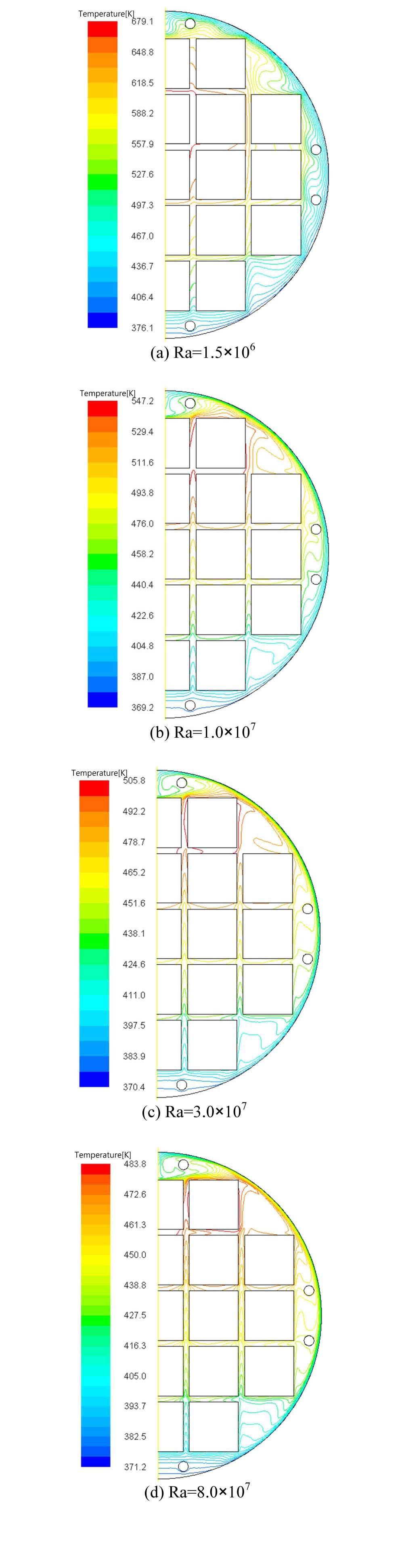
Temperature fields (isotherm lines) corresponding to the four values of Rayleigh numbers are shown in Fig. 5. In this figure, it can be noticed that the peak temperature is located at the second basket surface from the top along the vertical center line for all cases of Rayleigh number variation. The temperature of the baskets adjacent to the wall of the canister is lower than that of the baskets in the center region due to the local circulation occurring between these baskets and the canister wall.
In the case of Ra=1.5×10⁶, the temperature gradient between the basket walls and the inner surface of the canister is higher than in other cases. Also, this case shows a thermal stratification from the bottom region to the top region distinctly because the diffusion is dominant. As the Rayleigh number increases, the overall temperature gradients become smaller especially near to the inner surface of the canister and the thermal stratification starts to break at the upper region since the convection process becomes stronger. When the Rayleigh number arrives at Ra=8.0×10⁷, the isotherm lines are denser in the region near the canister wall than in other cases. This means that the convective heat transfer is dominating and the heat transfer due to the local circulation is stronger than that resulted from the global circulation.
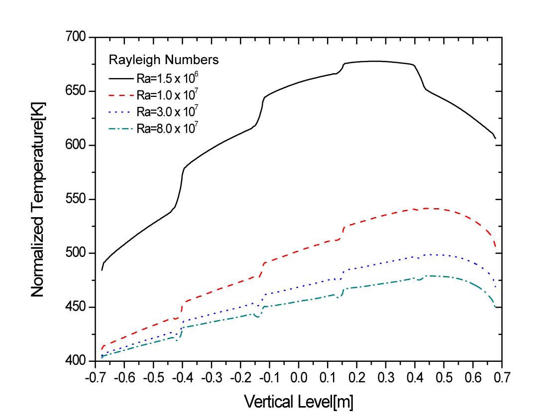
Figure 6 illustrates the temperature distribution on the right surfaces of the baskets along the symmetric line. In this figure, it is found that the peak temperature moves upward in the canister as the Rayleigh number increases. This is because the buoyancy effect becomes stronger when the Rayleigh numbers increase, and consequently, the velocity of upward flow in the gap increases. Also, it is found that the temperature gradient between the gap center and the basket surface becomes larger, and the temperature difference increases because of the buoyance effect when the Rayleigh number increases. A variation of the Rayleigh
number induces the great temperature change in the top region of the baskets comparing to the bottom region. In other words, the change of the temperature at the top region of the baskets is around 150℃ when the Rayleigh number varies from 1.5×10⁶ to 1.0×10⁷, while the change of the temperature at the bottom region of the baskets is only 74℃. The reason for these phenomena is a combined effect of the following: a path of the heat transfer by the natural convection is formed as the upward flow through the gap between baskets with the gaining of heat and the downward flow along the surface of the canister with the losing of heat; and the acceleration of the natural convection due to the increase of the Rayleigh number also leads to the resultant heat transfer enhancement between the baskets and the canister.
Figure 7 illustrates the difference between the average temperature of the basket surfaces and the average temperature of the inner surface of the canister. The temperature difference is remarkably reduced as the Rayleigh number increases. It is suggested that the heat transfer coefficient is proportional to some power of the Rayleigh number.
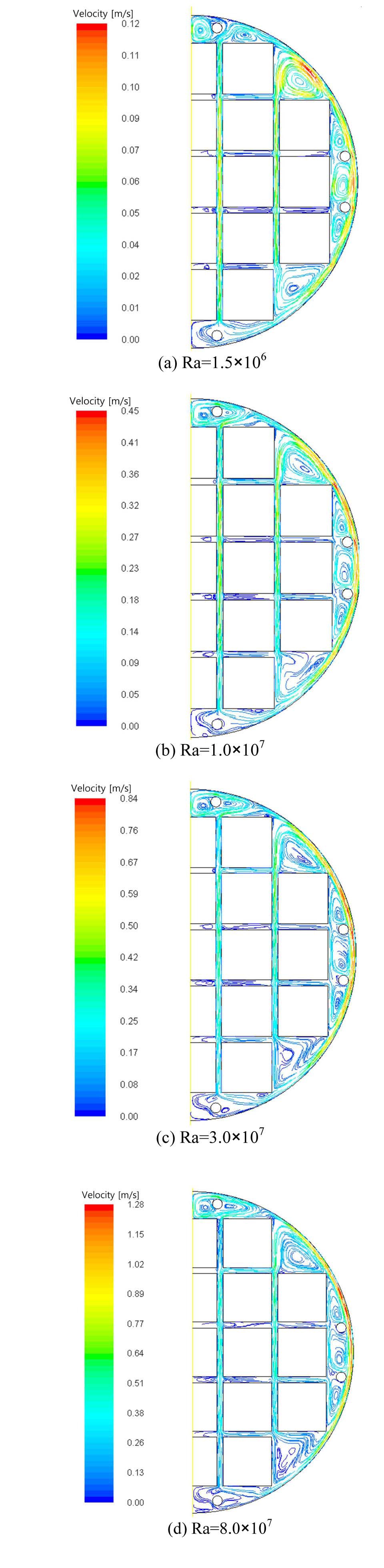
Velocity fields (stream lines) corresponding to the four values of Rayleigh numbers are given in Fig. 8. This figure illustrates that the flow patterns are characterized by two circulation regions. One is the global circulation consisting of the upward flow heated by the vertical walls of the baskets and the downward flow cooled by the canister inner surface. The other is the local circulation which takes place in the upper corner cavity formed by the walls of the two upper corner baskets and the inner surface of canister. The vertical flow through the gaps between the basket walls is more dominant when compared to the horizontal flow, and makes the temperature become uniform at the position of the same height level in the vertical gaps between
the baskets in the case when the Rayleigh number is higher than 1.5×10⁶. Figure 8 also illustrates the effect of the Rayleigh number on streamlines at four values of the Rayleigh number. When the Rayleigh number increases, it is found that the velocity magnitude values of the internal flow become higher and the convection effects become stronger. Furthermore, the local circulation becomes active and the heat transfer due to this local circulation becomes greater than that induced by the global circulation. The local circulation is especially developed widely in the upper cavity above the top baskets when the Rayleigh number becomes more than 1.0×10⁷. This circulation disturbs the upward flow in the vertical gap between the upper two baskets and eventually horizontal flow is developed in the horizontal gap.
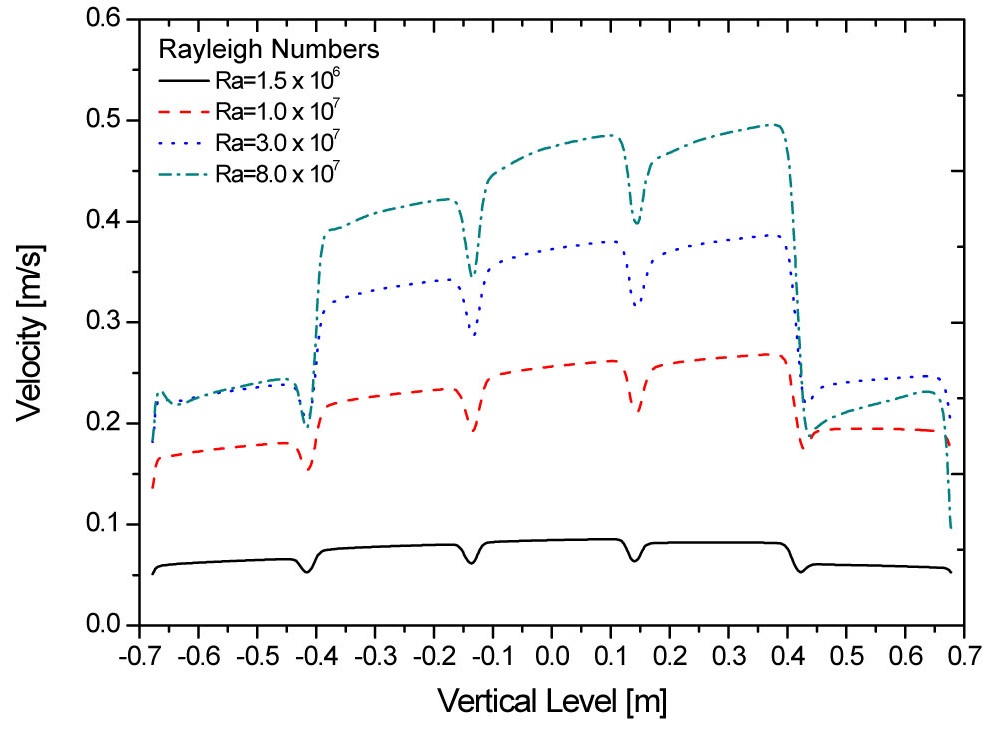
Figure 9 illustrates the velocity distributions in the vertical gap between the center baskets and the baskets next to the center baskets withthe four value of the Rayleigh number. In this figure, it is found that the velocity gradient and magnitude become larger as the Rayleigh number increases. However, it is remarkable that the velocity magnitude of Ra=8.0×10⁷ is smaller than that for Ra=3.0×10⁷ in the vertical gap between the top-most two baskets. The principal reason for this result is that the local circulation becomes stronger in upper cavity above the top baskets and it blocks the way of upward flow in the vertical gap when the Rayleigh number increases.
>
Heat transfer characteristics
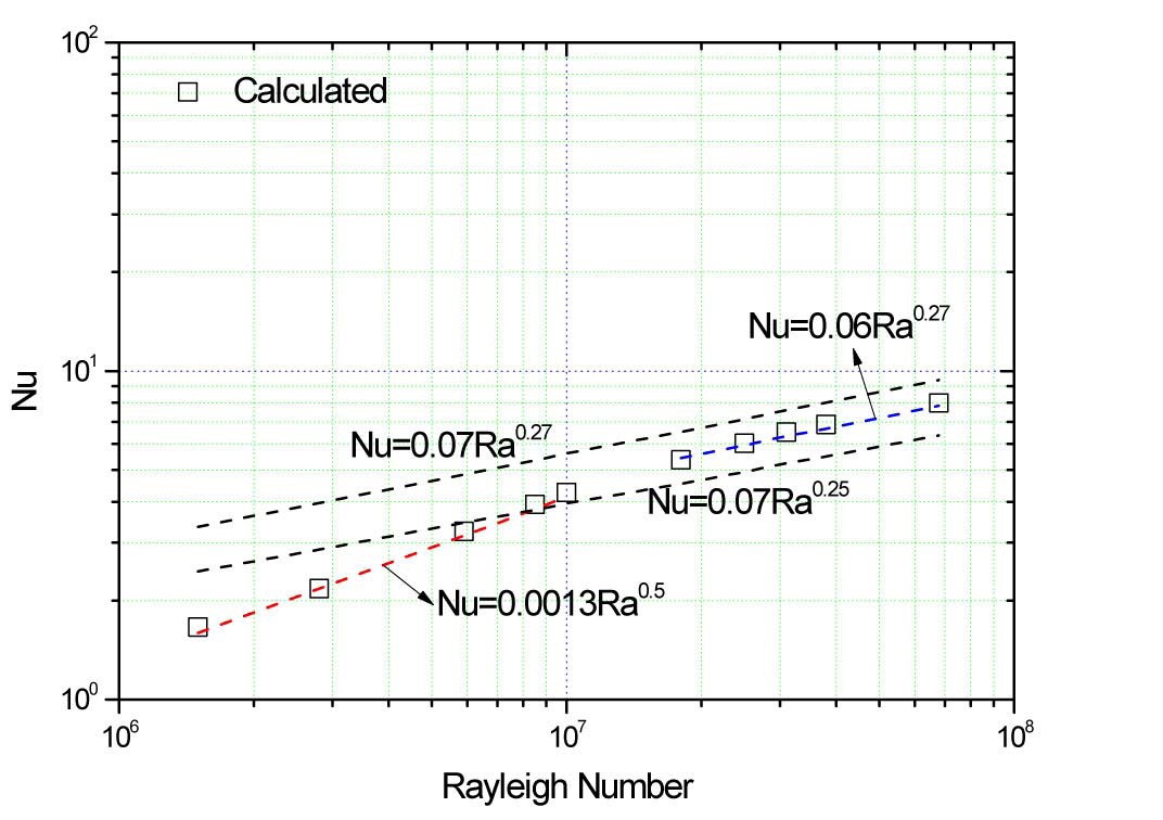
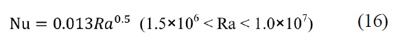
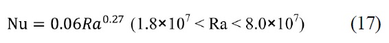
The heat transfer characteristics in the canister cavity are described by the correlation of the average Nusselt number on the basket surfaces with a function of the Rayleigh number as shown in Fig. 10.
Nusselt numbers in the range of 1.5×10⁶
are proportional to a 0.27 power of the Rayleigh number. This results show that the heat transfer characteristics for 1.5×10⁶
In spite of difference in the range of low Rayleigh numbers, the overall flow pattern and temperature distribution show the similar trends to the results of Nishimura et al. However, the heat transfer coefficient of helium increases more rapidly than that of air as the Rayleigh number increases in the range of 1.5×10⁶
The heat transfer coefficients have similar trends to those of air. Therefore, the regimes for the heat transfer characteristics resulting from this study can be summarized as follows:
The full-sized model for the horizontally oriented metal cask containing 21 spent fuel assemblies has been considered to evaluate the internal natural convection behavior within a DSC filled with helium as a working fluid.
A variety of two-dimensional CFD numerical investigations using a turbulent model have been performed to evaluate the heat transfer characteristics and the velocity
distribution of natural convection inside the canister.
The numerical predictions from simulations have been compared with the experimental data reported by Nishimura et al. Consequently, the results have shown that the average heat transfer coefficients are approximately correlated by Nu Ra0.27 for laminar and turbulent model in the range of 3×10⁶ < Ra < 2×10⁷. Therefore, the present simulation results have agreed well with the experimental results for air as working fluid.
The predicted temperature field has indicated that the peak temperature is located at the second basket from the top along the vertical center line by effects of the natural convection.
As the Rayleigh number increases, the convective heat transfer becomes dominant and the heat transfer due to the local circulation becomes stronger than that induced from the global circulation.
The heat transfer characteristics have shown that the Nusselt number is proportional to a 0.5 power of the Rayleigh number in the range of 1.5×10⁶
cp = fluid specific heat (J/kg-K)
ui, uj = velocity vector (m/s)
U = = the component of flow velocity parallel to the gravity vector (m/s)
V = the component of flow velocity perpendicular to the gravity vector (m/s)

= time-averaged fluctuating velocity (m/s)
P = pressure (Pa)
P0 = operating pressure (Pa)
gi = acceleration due to gravity (m/s2)
Gk = generation of turbulent kinetic energy due to mean velocity gradients
Gb = generation of turbulent kinetic energy due to buoyancy
Rε = Strain rate term written as a function of the mean rate-of-strain tensor
YM = Contribution of fluctuating dilation to the dissipation rate
T = temperature (K or ℃)

= time-averaged fluctuating temperature (K or ℃)
R = gas constant
H = heat transfer coefficient (W/m2K)
qs = heat flux (W/m2)
T0 = operating temperature (K or ℃)
Ts = average temperature of the basket surfaces (K or ℃)
Tc = average temperature of the inner surface of the canister (K or ℃)
Nu = Nusselt number
Ra = Rayleigh number
Rc = inner radius of the canister (m)
Pr = Prandtl number
αk, αε = inverse effective Prandtl number
τij = viscous stress tensor (N/m2)
λ = thermal conductivity (W/m-K)
k = turbulent kinetic energy (m2/s2)
ε = turbulent energy dissipation (m2/s3)
ρ = density (kg/m3)
ρ0 = reference density (kg/m3)
Φ = dissipation
μ□ = molecular viscosity (m2/s)
μt = turbulent viscosity (kg/m-s)
μeff = Effective viscosity (kg/m-s)
σt = turbulent Prandtl number
β = thermal expansion coefficient
ν = kinematic viscosity (m2/s)

= Viscosity ratio
δij = Kronecker delta