The purpose of this study is to solve the problems of radio frequency bandwidth frequency depletion, confusion possibilities, and security that are in current wireless communications systems, and to confirm the possibility of applying those solutions for the next generation network. To solve the problems of the current wireless communications system, a visible light communications system for power line communication (PLC) via 8-bit microcontroller is created and the capacity is analyzed. The exclusive PLC chip APLC-485MA, an 8-bit ATmega16 microcontroller, high brightness 5pi light emitting diodes (LEDs), and the LLS08-A1 visible light-receiving sensor were used for the transmitter and receiver. The performance was analyzed using a designed program and an oscilloscope.The voltage change was measured as a function of distance from 10-50 cm. Blue LEDs showed the best performance among the measured LED types, with 0.47 V of voltage loss, but for a distance over 50 cm, precise data was not easy to obtain due to the weak light. To overcome these types of problems, specific values such as the changing conditions and efficiency value relevant to the light emitting parts and the visible light-receiving sensor should be calculated, and continuous study and improvements should also be realized for better communication conditions.
Visible light communications technology uses visible light(380-780 nm) to deliver information without the effects of electromagnetic waves, keeping pace with current wireless communications.Lights of general fluorescent lamps or the visible light of light emitting diodes (LEDs) are flickered at visible speeds to send information. Visible light communication does not have any possibility of leaking out when the light is isolated, which offers better security than wireless LAN, and does not suffer performance losses even when a variety of computers are connected at once. This technology is also notable because it uses ecofriendly IT green technology rather than electromagnetic waves,which can cause harm to the human body [1].
In addition, due to the decreasing prices of LEDs and improvements in their light emitting efficiency, LEDs are now used in special lighting applications such as mobile device displays, cars,traffic signs, and advertisement panels, as well as in the general lighting market, such as current fluorescent lamps or incandescent lights. Specifically, the emitting efficiency of the white LED has already surpassed that of the fluorescent lamp, and more outstanding products are appearing in the current market.
Recently, due to RF bandwidth frequency depletion, confusion possibilities, increasing security requirements, and super-speed ubiquitous communication environments, radio frequency technology and mutually complementary optical wireless communication technologies are being developed at a large number of companies and institutions worldwide [2].
The automatic voltage regulator (AVR) family, including the ATmega16 microcontroller, is a source of pride, with its super speed of order processing that applies the Harvard architecture,which uses the bus independently to access the internal data memory and the reduced instruction set computer based on the pipeline processing method. Also, AVR includes flash memory for the program code inside the chip and applied in system programming that downloads the user program on the memory. The ATmega16 element is inexpensive and provides the AVR studio and macro assembler integrated design environment software for free. It also includes the use of WinAVR, which is a GNU Compiler Collection C compiler.
This study will confirm the possibility of applying this technology for the next generation wireless network by creating a visible light communication transmitter and receiver for power line communication (PLC) using an 8-bit microcontroller [3,4].
Visible light communication technology, which has gotten notice as a next generation communication technology, is particularly attractive for home networks. Among the technologies, the visible light communication system is designed and brought into a network using PLC to study application of the LED system that is necessarily relevant for living [5].
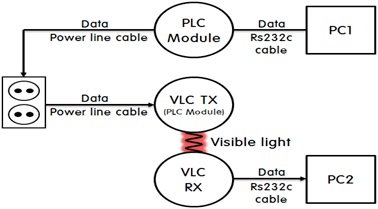
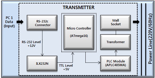
The visible light communication system based on PLC uses a commercial alternating current electric power source 220 V/60 Hz power line and an RS-232C cable as a communication medium,and consists of visible light communication parts including PLC receiving and transmitting parts. The system developed in this study transmits the input data from a computer to a PLC transmitter through an RS-232C port. This signal is converted into the transistor-transistor logic (TTL) signal level through an ILX232N chip, and is transmitted to the PLC receiver through a power line cable after the data is transmitted to an exclusive PLC chip through an 8-bit microcontroller. Data that is transmitted after these processes is received by an exclusive PLC chip that is attached to the PLC receiver, and this signal passes through the 8-bit microcontroller and is transmitted to the visible light communication light emitting parts. After the data is received from the visible light receiving sensor through the LED of the visible light communication light emitting parts, the lowered data signal is amplified by the OP-amp circuit, and the RS-232C cable is used through the Microcontroller and the ILX232N chip to send the data to other computers.
The design in this study uses a commercial alternating current electric power source, a 220 V/60 Hz power line as the communication medium, and the system shown in Fig. 1 to transmit the information.
The distance between the light emitting parts and the receiving parts of the visible light communication should be between 10-50 cm, and each LED should be positioned horizontally. Each transmitting and receiving part has its own LED in order to verify the information transmitting and receiving process so that the conditions and power conditions can be checked in real time.
Real time checking of the transmitted and received data is achieved by using the Visual C computer programming language. The visible light communication data transmitting and receiving program uses letters so that the data transferred between computers can be checked by eye. In this manner, the performance of the processes can be monitored and evaluated. In this process, the transmitting and receiving port drivers of both computers should be well connected in order to communicate.
Figure 2 is the circuit image of the PLC receiver used in this study. The PLC receiver mainly consists of the exclusive APLC-485MA PLC chip, an 8-bit microcontroller ATmega16 chip, and an ILX232N chip for the TTL signal level change.
The ILx232N chip balances the voltage gap for the serial communication between the PC and the microcontroller. When data is transmitted using the RS-232C cable in PC1, the data is transmitted to the power line through the exclusive PLC chip and the 8-bit microcontroller.
2.3 PLC receiver and visible light communication transmitter
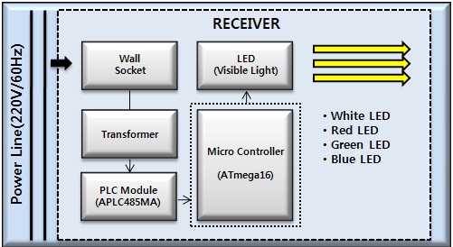
This part of the system has a similar composition to the PLC receiver, except that 3 of the 5pi LEDs are added to the light emitting parts design. The signal that comes through the power line is received through the exclusive APLC-485MA PLC chip,and is transmitted to the LED through the 8-bit microcontroller ATmega16 chip. Figure 3 shows the transmitter circuit image of the visible light communication system.
2.4 Visible light communication receiver
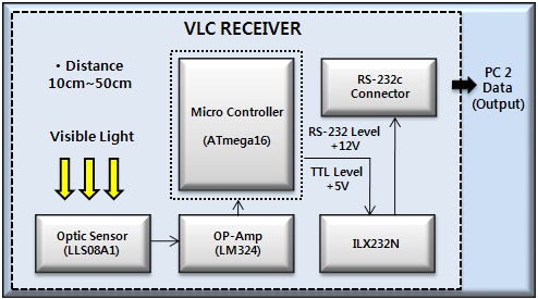
The composition of the visible light communication receiver is different than that of the PLC transmitter or visible light communication receiver, as shown in Fig. 4. The visible light communication receiver does not have an exclusive PLC chip, so it only has a visible light receiving sensor and an 8-bit microcontroller to receive the information. The data is received in PC2 through ATmega16, which is an 8-bit microcontroller, and OP-Amp LM324N after the data is received from the LED through the LLS08-A1 visible light receiving sensor [6,7].
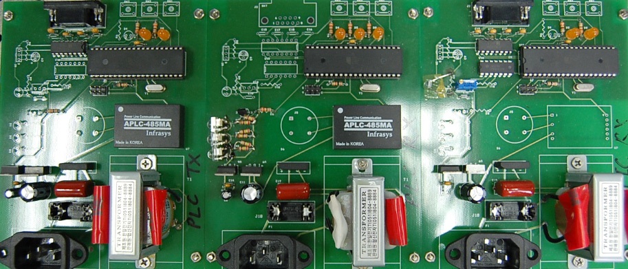
2.5 Manufactured transmitter and receiver
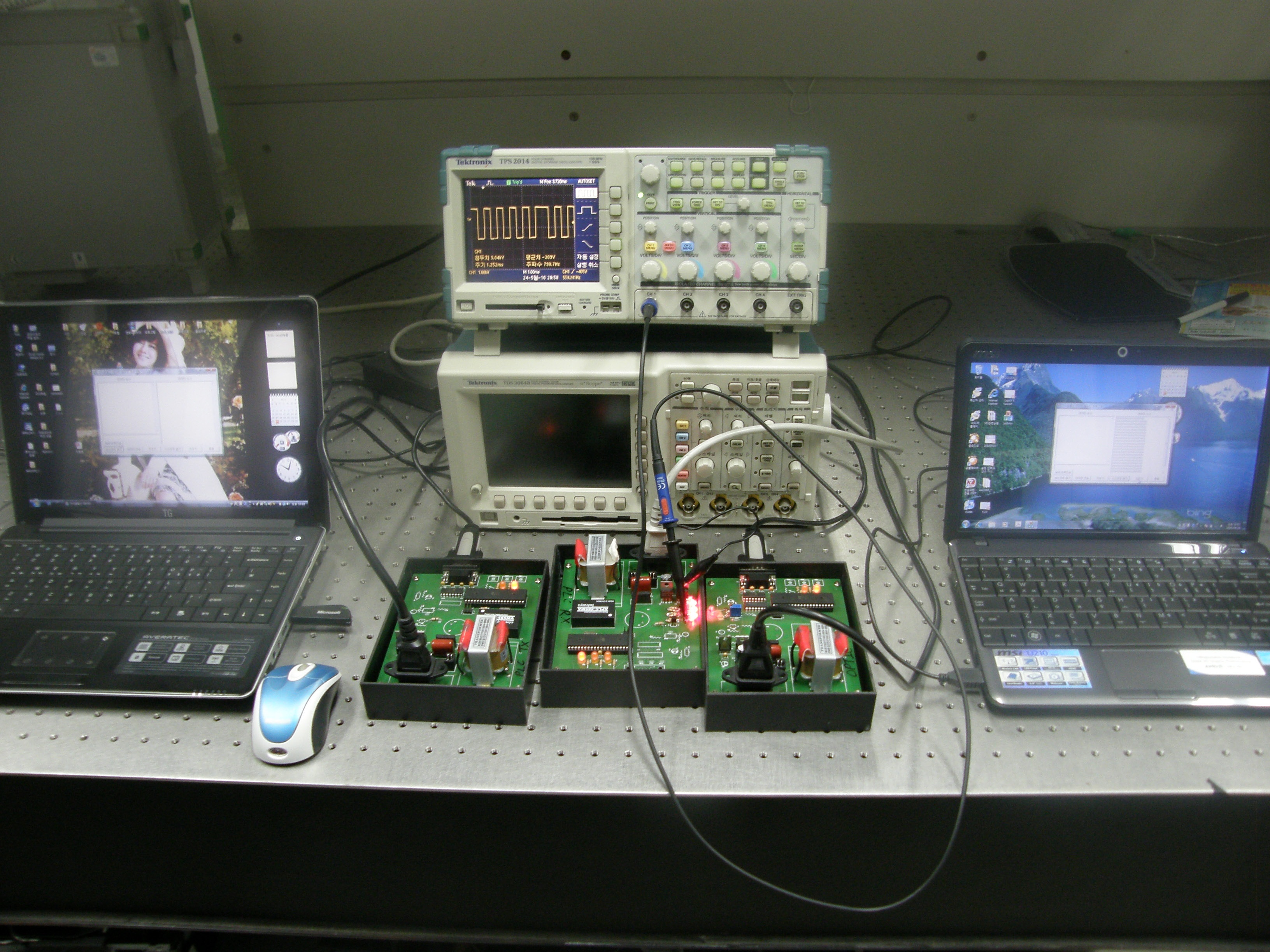
Figure 5 shows the final system after the design of the PLC transmitter and the visible light communication receiver and transmitter of the PLC based visible light communication system.The left side of Fig. 5 shows the PLC transmitter, the center shows the visible light communication transmitter, which includes the PLC receiver, and the right side shows the visible light communication receiver.
Figure 6 shows the process in which the letters are transmitted and received. The transmitter and receiver of the materialized system are connected directly to the RS-232C port of the computer, and the output value is calculated, which is detected by the visible light receiving sensor using an oscilloscope. The transmitting and receiving waveforms can be checked and verified as shown in Fig. 6.
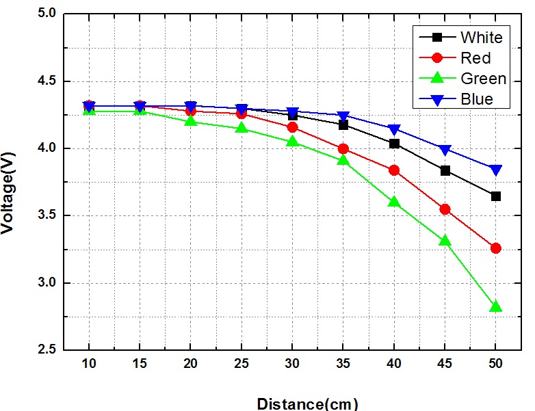
Figure 7 shows the values obtained from voltage change through visible light receiving sensor from a voltage that 5 V is approved by distance using an oscilloscope. In the case of the white LED, the voltage at a distance from 10-35 cm was constant,but the voltage for a distance over 35 cm showed a dramatic voltage decrease. A voltage loss of 0.67 V was confirmed, with a voltage of 4.32 V at 10 cm to a voltage of 3.65 V at 50 cm. Also, in the case of the red LED, the voltage from 10-30 cm was constant,but there was a dramatic voltage decrease at distances over 30 cm. At a distance of 50 cm, the voltage was 3.26 V, so that 1.06 V was confirmed as the voltage loss. The voltage loss of the green LED is 1.46 V, and the voltage loss of the blue LED is 0.47 V, which shows the best performance among the LEDs.
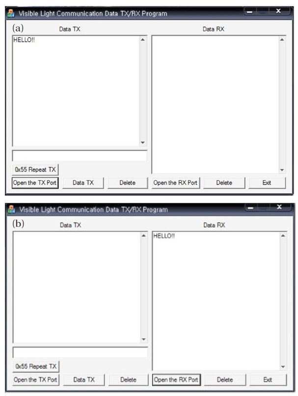
Figure 8 shows the Visual C program that general users can easily take and adapt by adding letters to verify successful data transmissions between the computers. In this manner, "HELLO!!"was used as the input and was transmitted to the other computer. The results were checked, and the blue LED showed the best performance when evaluated using an oscilloscope.
In this study, a visible light communication system for PLC was created, and a simple experiment was created to verify the system performance using a Visual C program and an oscilloscope.The performance analysis was done by color at communication distances from 10-50 cm with 5 V, and showed that voltage loss can be observed. As a result, the blue LED showed the best performance at distances from 10-50 cm, and there were no problems in the Visual C program while the letters were transmitted and received. As the distance increased, however,the processing speed decreased due to the weak signal treatment and the background lights, which made it hard to receive precise data. Also, new issues were found by using the estimated values.In this study, the performance under changing conditions was evaluated, and the efficiency of the light emitting part and the receiving sensor of the visible light were studied so that better communication conditions can be achieved in the future. Continuous study and improvement are required. This study also confirmed the possibility of applying this technology for the next generation network.