Nano-sized MgO single crystal powders have recently been reported to emit ultraviolet by stimulation of electrons in a vacuum. In this study, nanocrystalline MgO powders were applied to a xenon plasma flat fluorescent lamp (FFL) for a liquid crystal display backlight to improve its emission efficiency through the extra ultraviolet from the nano-MgO crystals. For comparison, a MgO nano-thin film was applied directly on the phosphors inside a lamp panel through e-beam evaporation. Adding MgO nano-crystal powders to the phosphors improved the luminance and efficiency of FFLs by around 20% and MgO nano-crystal coverage of 40% of the phosphor provided the best FFL emission characteristics; however, application of MgO thin film to the phosphors degraded the emission characteristics, even compared to FFLs without MgO. This was due to insufficient ultraviolet stimulation of the phosphors and the crystallinity and low secondary electron coefficient of the MgO.
A xenon plasma flat fluorescent lamp (FFL) is desirable for a LCD backlight because of its excellent emission uniformity compared with the line emission source of a conventional cold cathode fluorescent lamp (CCFL) or the point emission source of a light emitting diode. In addition, the xenon lamp does not contain mercury gas, which is environmentally hazardous [1,2]. In spite of these advantages, there is a barrier to its imminent commercialization as an liquid crystal display (LCD) backlight. Since the luminous efficiency of a xenon lamp is quite low compared to a CCFL, due to its low UV emission, it consumes more power and emits more heat.
It has been recently reported [3] that nano-sized MgO single crystals in the range of a few hundred nanometers emit ultraviolet (UV) under a vacuum due to stimulation of electrons. MgO materials also have a large secondary electron yield, possibly leading to increased UV emission from a xenon plasma, and a low sputter yield, leading to a protective layer.
In this study, nano-sized MgO single crystal powders were applied over phosphors inside a xenon lamp panel to improve its luminous efficiency through the extra UV emission from MgO single crystals. For comparison, another panel was fabricated with a coating of nano-sized MgO over phosphor by e-beam evaporation and their emission characteristics were measured.
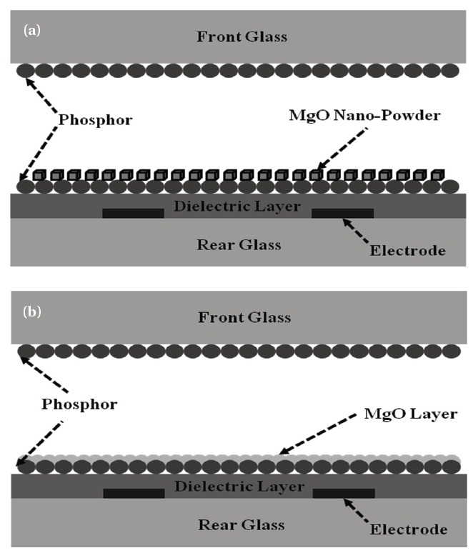
Figure 1 shows the schematic diagram of a xenon plasma FFL with both MgO nano-crystals and MgO thin films. PD-200 (Asahi glass Co., Tokyo, Japan) was used as the panel glass because it does not deform even at firing temperature. Silver paste (Taiyo Ink) was used as an electrode material for good conductivity. To protect the electrode from ion bombardment, the electrodes were covered with a dielectric material. The white phosphor used in this study is composed of 33% red (Y2O3:Eu), 33% green (LaPO4:Ce,Tb), and 34% blue (BaMgAl10O17:Eu) phosphors. Printing, sealing, and gas control proceeded using a screen printer (Bando Industrial), a dispenser (Musashi Engineering), and a
sealing system (Avaco). For assembling the FFL panel, silver electrodes, a white back dielectric layer, and a phosphor layer were screen printed on the rear glass and fired at 550, 450, and 570℃, respectively, in sequence. Another phosphor layer was printed on the front glass and fired in the same manner as for the rear glass.
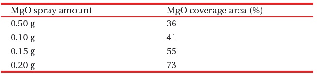
MgO nano-crystals ~200 nm in diameter were dispersed in a methanol solution by sonication for several minutes and then sprayed over the phosphors, as shown in Fig. 1(a). The amount of sprayed MgO powder varied from 0.05 to 0.20 g over an 8.5 × 7.5 cm emission area. The coverage area of the sprayed MgO powders was measured with an image analyzer, as shown in Table 1. On another sample, MgO thin film (200 nm thick) was deposited on the phosphors by e-beam evaporation, as shown in Fig. 1(b).
Both the front and rear glasses were sealed at 450℃ and then pumped out under a pressure of 10-3 torr at 150℃ for 60 min to completely remove organic residues. Xe gas was injected after vacuuming at 10-6 torr for efficient plasma discharge. The luminance characteristics of the two types of FFL were compared and characterized using a spectra-radiometer (CS-1000A; Minolta, Japan) and a square pulse power supply (PDS-4000; Ftlab, Korea).
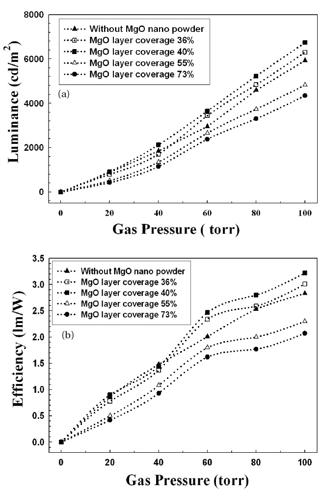
Increasing the xenon gas pressure inside the panels improved the luminance and efficiency of t he FFLs, as shown in Fig. 2. When a plasma is generated by electrons excited from an applied voltage, the luminance and efficiency are affected by the gas pressure. As the gas pressure increases, the collision between xenon atoms and electrons becomes remarkably frequent, leading to more emission of ultraviolet and stimulation of the phosphors.
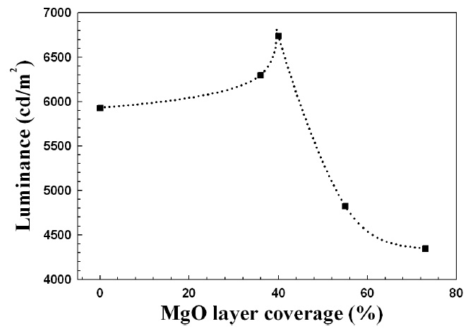
From Figs. 2 and 3, the luminance and efficiency of FFL increased for MgO coverage of up to 40%, and then abruptly decreased for coverage above 40%. The more MgO nano-crystals on the phosphors, the greater the emission of ultraviolet and the
[Table 1.] MgO coverage area on 8.5 ?? 7.5 cm emission area.

MgO coverage area on 8.5 ?? 7.5 cm emission area.
greater the stimulation of the phosphors; but if the MgO powders cover too much of the phosphor area, the stimulation of the phosphors is reduced because the MgO powder shades the phosphors from UV.
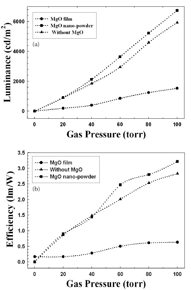
Figure 4 shows the luminance and efficiency of FFLs with MgO nano-crystals (40% coverage) and MgO thin film. Adding MgO nano-crystals improved the luminance and efficiency by around 20% compared with the panels with no MgO crystals. The MgO nano-crystal effect was notable at a gas pressure above 40 torr. However, for FFLs with MgO film coating on the phosphors, the emission characteristics were even worse than for FFLs without MgO. Because the top surface area of the phosphors on the rear glass was completely coated by the evaporated MgO film (i.e., a large coverage area), the stimulation of phosphors by UV was inefficient.
The crystallinity of the MgO thin film is quite crucial to the emission characteristics because the amount of UV emission
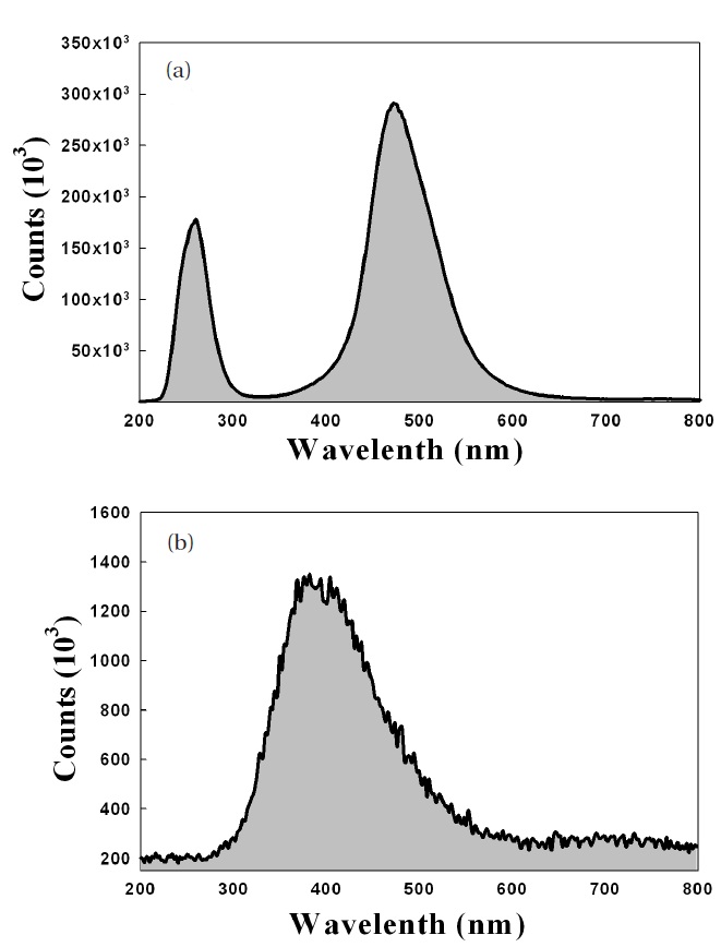
from MgO is affected by the number of defects in the MgO crystals. Figure 5 gives the cathode luminescence (CL) data of MgO nano-crystals and MgO thin films
The MgO nano-crystals emitted ultraviolet in the range of 200 to 300 nm; however, for MgO thin films, no strong UV peak appears
in the CL data. This phenomenon can be interpreted by the following expression.
where Eg is the band gap energy of MgO (7.8 eV = 12.48 × 10⁻¹⁹ J),
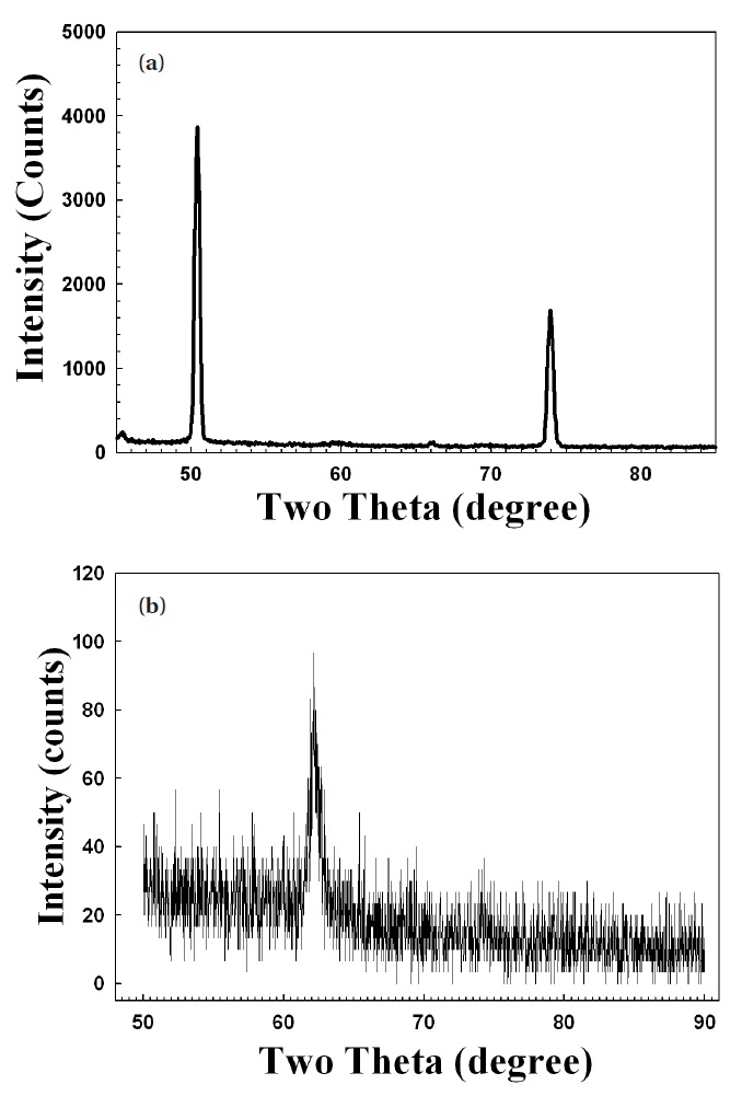
The X-ray diffraction data, shown in Fig. 6, proved that the crystallinity of MgO nano-crystal was superior to that of MgO thin film. This agreed well with the CL results shown in Fig. 5.
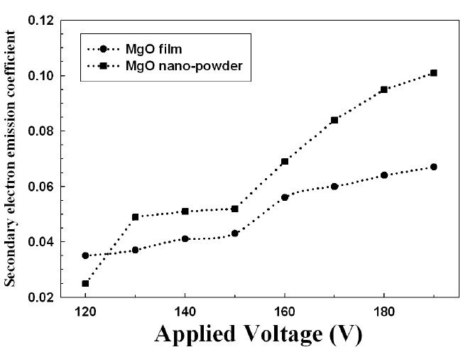
Figure 7 shows the secondary electron coefficient (γ) of MgO nano-crystals and thin film. The γ of MgO thin films is lower than the γ of MgO nano-crystals, which is also related to its crystallinity.
The luminance and efficiency of an FFL with added MgO nano- crystal powders on the phosphors were improved by around 20%. A MgO nano-crystal coverage of 40% of the phosphors was found to give the best FFL emission characteristics. Application of MgO thin films to the phosphors degraded the emission characteristics, even compared to FFLs without MgO. This was due to insufficient stimulation of the phosphors by UV and the crystallinity and low secondary electron coefficient of MgO.