With soaring public concerns of environmental issues, many researchers have started to carry out research on various related topics in many areas of science and engineering. This paper describes a brief outline of typical recent research results obtained in the author’s laboratory on electrical and optical properties of dielectric materials, done aiming at contributing to green power technology.
Various environmental issues such as the global warming effect have become today's major public concerns throughout the world. Therefore, researchers have to make more effort to carry out research that can contribute to environmental protection.This is of course the case in the research on electrical and electronic materials. On the occasion of being invited to the KIEEME Annual Conference 2010, the author feels honored to introduce several examples of research done in his laboratory at Waseda University on electrical and optical properties of solid dielectric materials, aiming at making such contributions.
The author is now doing research on the following four topics with the help of his students and research associates:
1) Development of a full-length condition monitoring method of cable aging, especially for nuclear power plants [1], which can contribute to eco-friendly power generation.
2) Study on dielectric properties of eco-friendly biodegradable polymers to enlarge their applications [2].
3) Development of nano- and micro-processing of solid dielectric materials using ion implantation, which should lower power consumption [3].
4) Development of insulating materials with a long lifetime,which should save natural resources [4].
In this paper, typical examples of the research results are briefly reported.
2. MONITORING OF CABLE AGING
Many pieces of electric wire and cable with a total length of more than 1,000 km are used in a nuclear power plant, and they play important roles such as supply of electric power and transmission of information and control signals. Some of them, classified as safety-related equipment, must function even after the design basis events such as the loss of coolant accident (LOCA) as well as during the whole period of normal operation. Therefore, their integrity is of prime importance for the safety of nuclear power plants. In most cables, organic polymers that are very sensitive to radiation are used. Therefore,cable aging is caused by the degradation of polymers.With this background, Japanese government carried out an extensive research project to examine the degradation behavior of safety-related cables at three different temperatures with three different dose rates. Its report published recently revealed that some cables would be unable to function after the LOCA test [5].
In order to know the risk of occurrence of an accident incurred by cable aging, the author surveyed and categorized all the causes of malfunctions occurred in electric apparatus in all the Japanese nuclear power plants for recent about 40 years. As a result, it became clear that not a single trouble had occurred in any cable in any Japanese nuclear power plant by pure insulation degradation, indicating that the risk of serious accidents is very low [6]. Nevertheless, in order secure even higher reliability,knowing the change in various properties of polymers during their operation can be a key measure of the management of cable aging. In this regard, Japanese government has been supporting several research projects to develop a reliable monitoring method.
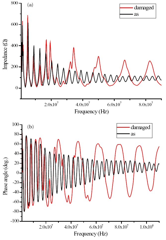
One of the monitoring methods being developed is the broadband impedance spectroscopy (BIS), and evaluation of its effectiveness is being carried out by the author together with his post-doctoral fellow and students. The BIS is a method to measure the changes in frequency spectra of cable impedance and phase angle in a very wide frequency range by applying a low voltage. The polymer materials used are special heatresistant polyvinyl chloride (SH-PVC), flame-retardant ethylene propylene rubber (FR-EPR), and cross-linked polyethylene(XLPE), which are commonly used for electrical insulation in cables in nuclear power plants. Figures 1 and 2 show typical examples of the condition monitoring tried using a cable, the initial characteristics of which are known. A part of insulating polymer of a 25-m long SH-PVC-insulated cable, about 0.8-m long, was peeled off at a point about 5.6 m distant from a measurement terminal.
A clear difference is seen in Fig. 1 for both the impedance and phase angle spectra measured by the BIS method before and after the damage. It is clearly seen that the frequency intervals where the impedance and phase angle show their maxima or minima change by the damage. The number of impedance minima that appear in each spectrum is shown in Fig. 2 as a function of frequency. The frequency interval is drastically increased by the damage from about 3.5 MHz to about 15 MHz in a frequency range above about 20 MHz. For a 25-m long cable with a characteristic impedance of 100 Ω, the frequencies of electromagnetic waves at which the products of their half wavelengths and integers become equal to 25 m appear every 3.5 MHz. Similarly, for a cable of 5.8-m long, they appear every 15 MHz. The proximity between the distance of the peeled portion from the cable end(5.6 m) and the above-mentioned cable length of 5.8 m indicates that the frequency interval seen in the damaged cable is caused by the reflection of the electromagnetic wave at the interface between the damaged and non-damaged portions. This fact implies that we can locate the position of a damaged portion in a cable by measuring frequency spectra of impedance and phase angle, even if the initial spectrum of the undamaged cable is not known.
To verify further the possibility of estimation of aged position in a cable by the BIS method, fast Fourier transform (FFT) analysis was carried out. The cable used consists of two cores with a length of 25 m and its PVC insulator was peeled off partially.The cable impedance was measured as a function of frequency of the voltage. The total number of impedance values measured was 801 points in a frequency range from 1 MHz to 110 MHz at 136.25-kHz intervals, and the spectrum thus obtained is shown in Fig. 3(a). Based on the spectrum, FFT analysis was carried out, and the result is shown in Fig. 3(b) as a function of distance from the measurement terminal. A strong peak is seen at around 6 m from the measuring terminal as shown in Fig. 3(b). This distance agrees with that of the damaged position, which indicates that the reflection at the boundary of the damaged and undamaged undamaged portions is large. Namely, the FFT analysis of BIS spectra can point out the position of the portion actually damaged by peeling off the insulator. Therefore, it was confirmed that the position of a damaged portion in a cable can be located by the BIS method.
Thermosetting resin and XLPE are widely used as electrical insulating materials in many pieces of electrical apparatus and cable. These polymer materials are not ecologically friendly,since they are not suitable for recycling. They can be re-used as fuel, but this would emit a global warming gas (CO2). In most cases, abandoned polymers are just discarded, which pollutes the earth.
Eco-friendly biodegradable polymers that can be decomposed by microbes have a potential ability to solve these problems.From this viewpoint, the author together with his post-doctoral fellow and students have been studying various dielectric properties such as complex permittivity, electrical conductivity, dielectric breakdown strength, partial discharge (PD) resistance,and resistance to water immersion in comparison to the properties of low density polyethylene (LDPE) for various biodegradable polymers.
The samples tested are commercially available biodegradable polymers; starch ester (SE), poly-L-lactic acid (PLLA), polyethylene terephthalate succinate (PETS), polycaprolactone (PCL),polycaprolactone butylene succinate (PCL-BS), polybutylene succinate (PBS), poly-butylene succinate adipate (PBSA), polybutylene adipate terephthalate (PBAT), polyhydroxybutyrate/valerate (PHB/ V), and their blends.
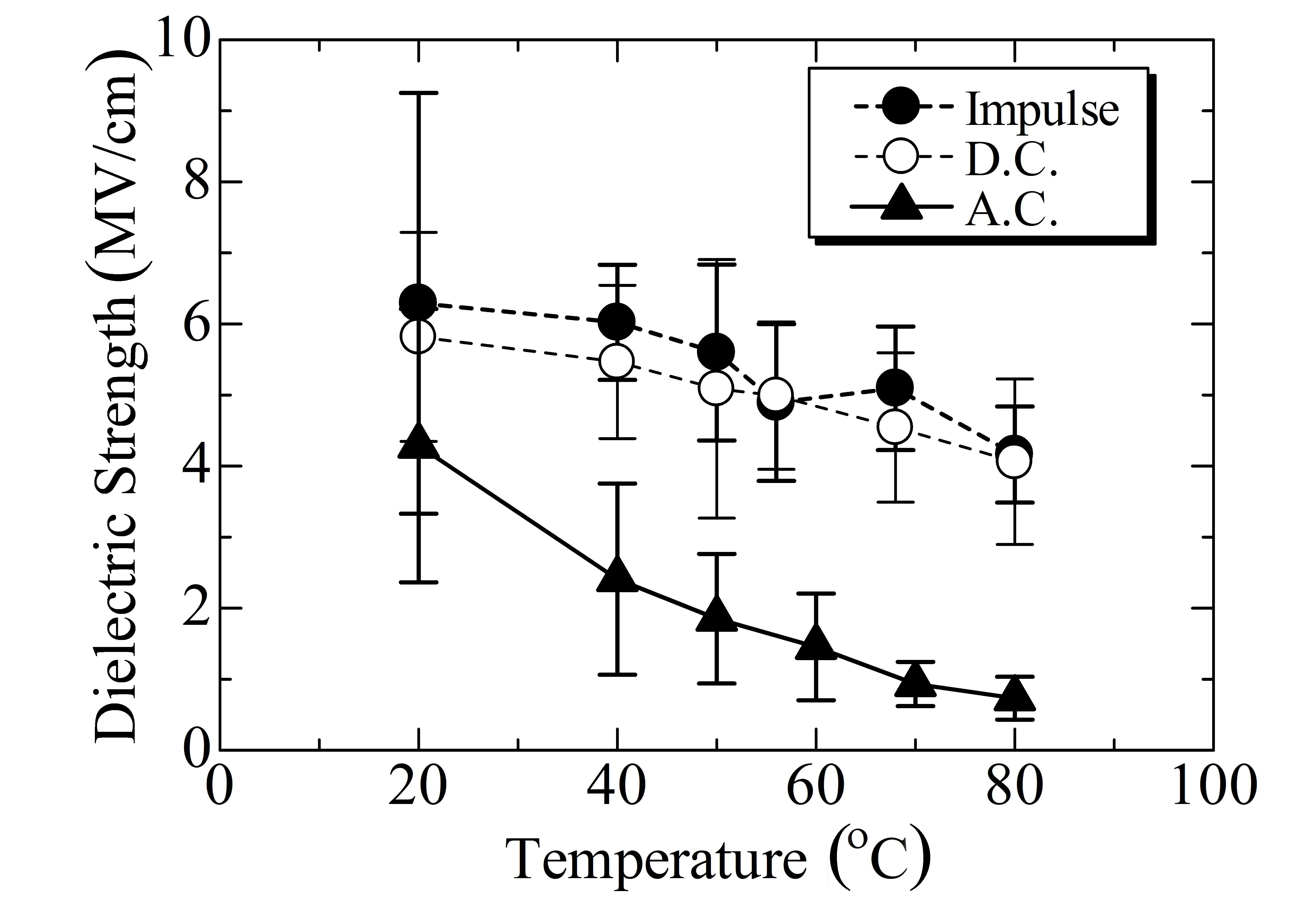
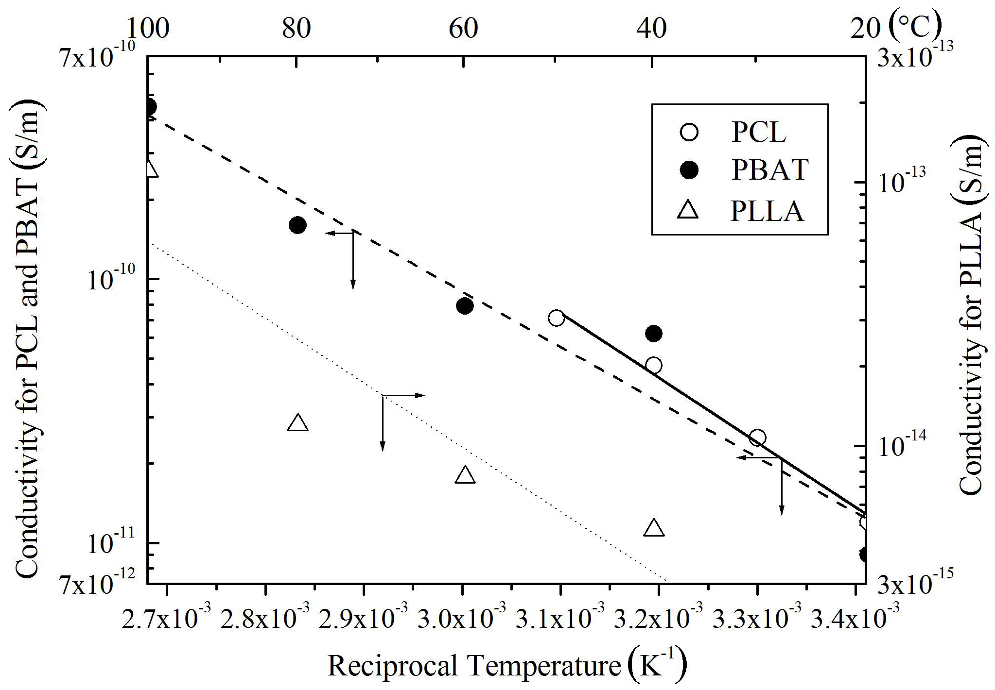
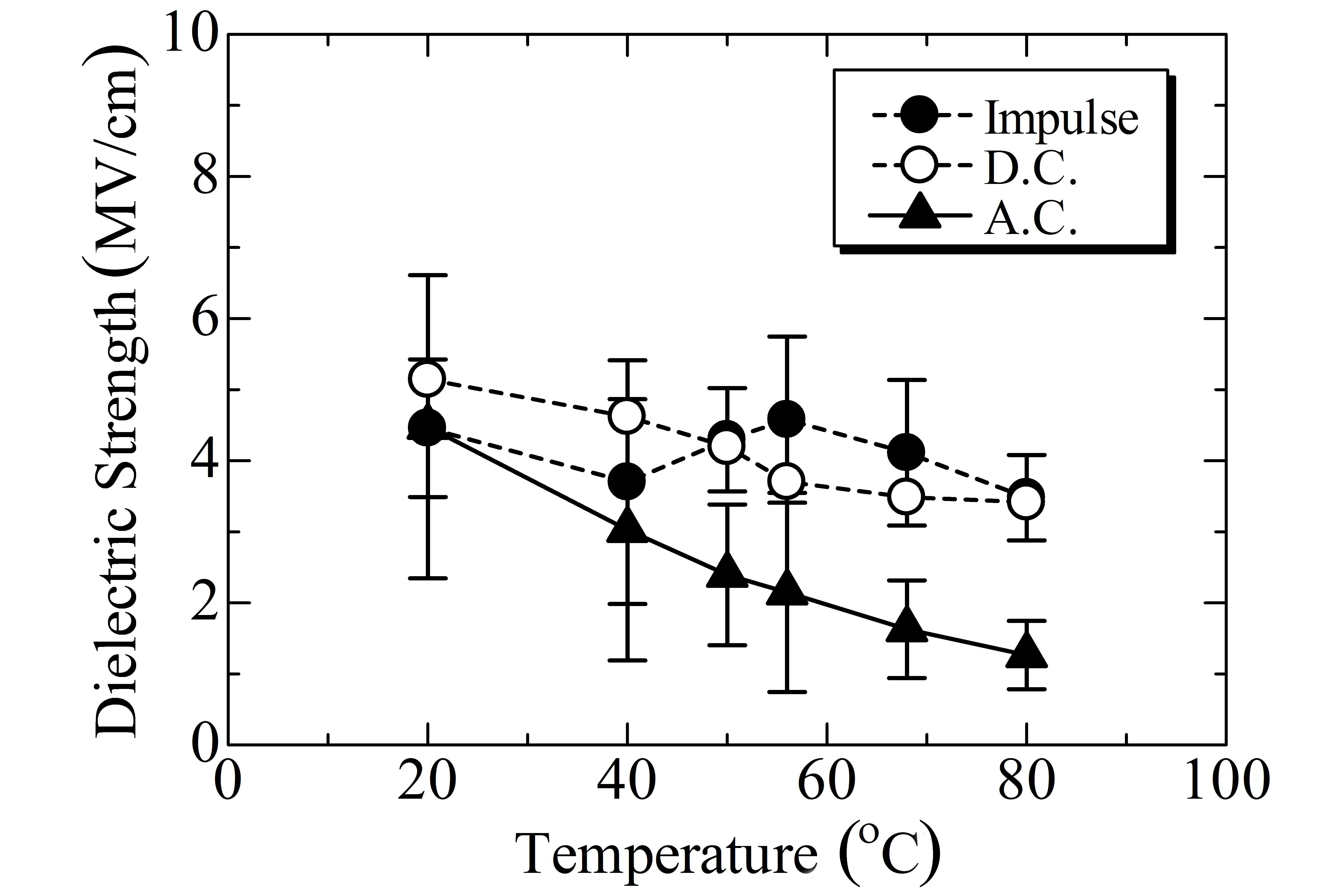
Among the nine polymers investigated, PLLA and PETS are in the glass state at room temperature, while the other seven polymers are in the rubber state. Partly because of this reason,the permittivity is much lower in PLLA and PETS than in SE, PCL, PCL-BS, PBS, PBSA, and PBAT. This tendency is also seen in conductivity as shown in Fig. 4. In contrast to such large differences in conductivity and permittivity, all the polymers investigated have an almost similar impulse breakdown strength at room temperature as shown in Fig. 5. As for dc or ac breakdown, in which the conductivity should theoretically play a more significant role than in the impulse breakdown,SE, PLLA, and PETS show a relatively higher strength than the others do.
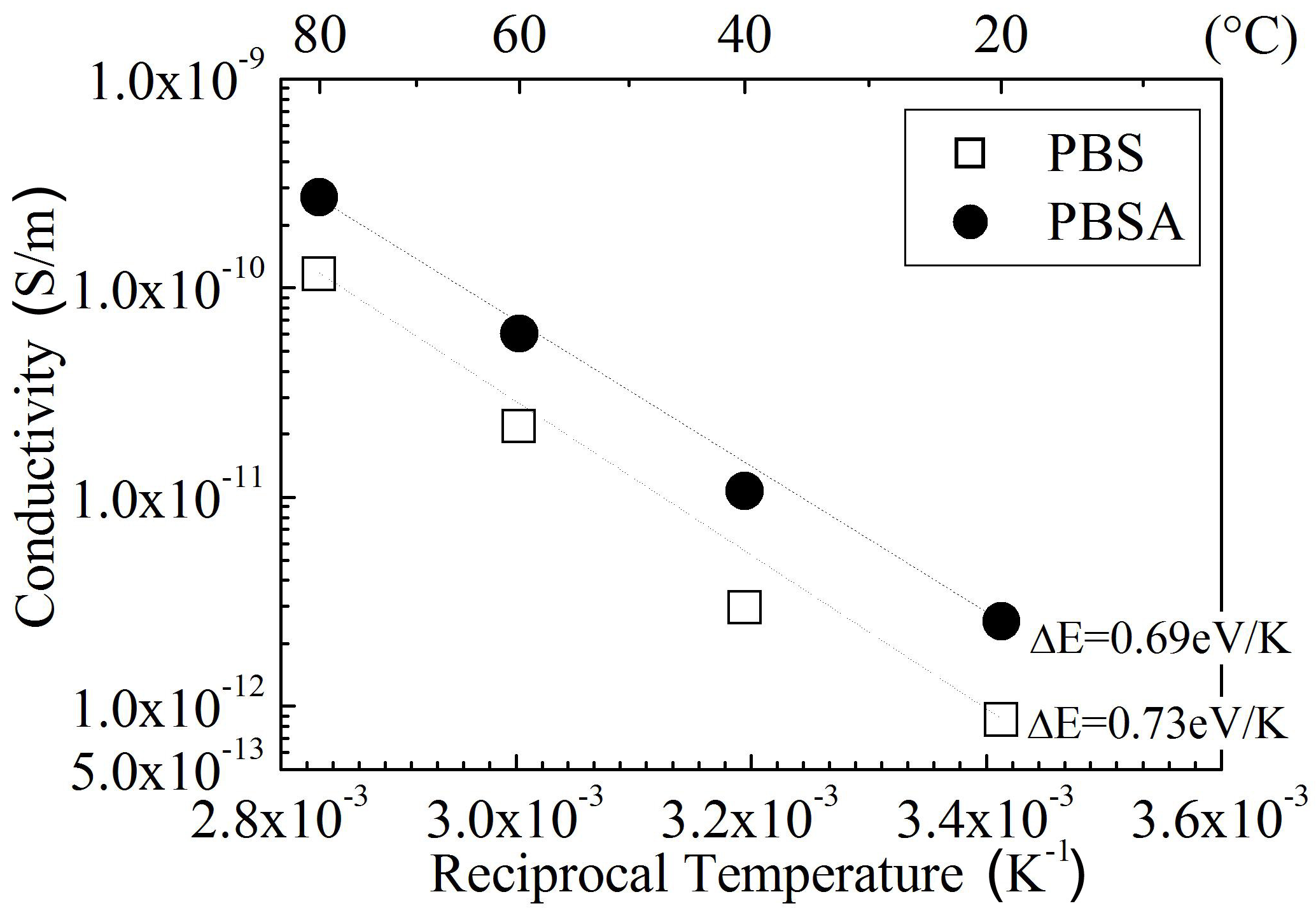
Figure 6 shows dc conductivity σ as a function of reciprocal temperature observed for SE blended with PCL, PBSA, or PBAT. The conductivity increases with an increase in temperature for all the samples, following the Arrhenius law. Judging from high conductivity values and sharp positive temperature dependencies, it seems that ions are dominant carriers for the electrical conduction in these samples. Namely, the increase in density of mobile ions and the expansion of free volume through which the ions can move with an increase in temperature are presumed to be responsible for the conductivity increase.
The results of PD resistance show that a good PD resistance can be achieved by the sample with a high crystallinity and a low permittivity, and that the PD resistance is ranked as LDPE > SE >PLLA ≊PETS > PBS > PCL-BS.
While the durability of biodegradable polymers against water is significantly reduced with an increase in water temperature, SE shows the best durability of the five kinds of biodegradable polymers investigated, namely, SE, PLLA, PCL-BS, PBS, and PETS,regardless of the water temperature. Furthermore, all three blend polymers of SE with PCL, PBSA, and PBAT show resistivity and ac breakdown strength much higher than the values requested for 600-V class insulated wires.
By considering the above-mentioned results, it is summarized that SE can be an electrical insulating material if the surrounding atmosphere is relatively mild, while PCL, PCL-BS, PBS, PBSA,PBAT, and PHB/V can be plasticizers for SE.
4. ION ASSISTED MICRO-PROCESSING
The density of a solid substance varies depending on its structure. In the case of a substance that can take both a crystalline and an amorphous form, the former usually has a higher density than the latter. Silica is a typical example of such substances. Therefore, when ions are irradiated to silica, the density is increased if the silica is glass (= amorphous), while it is decreased in the case of crystalline silica like quartz. As is well known, optical fibers and waveguides for telecommunication utilize a slight difference in refractive index between their core and cladding. Furthermore, the most important fiber/waveguide material is silica glass. Therefore, the increase in refractive index of silica glass induced by ion implantation should have a possibility of providing lots of applications to optical functional devices.
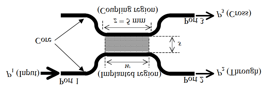
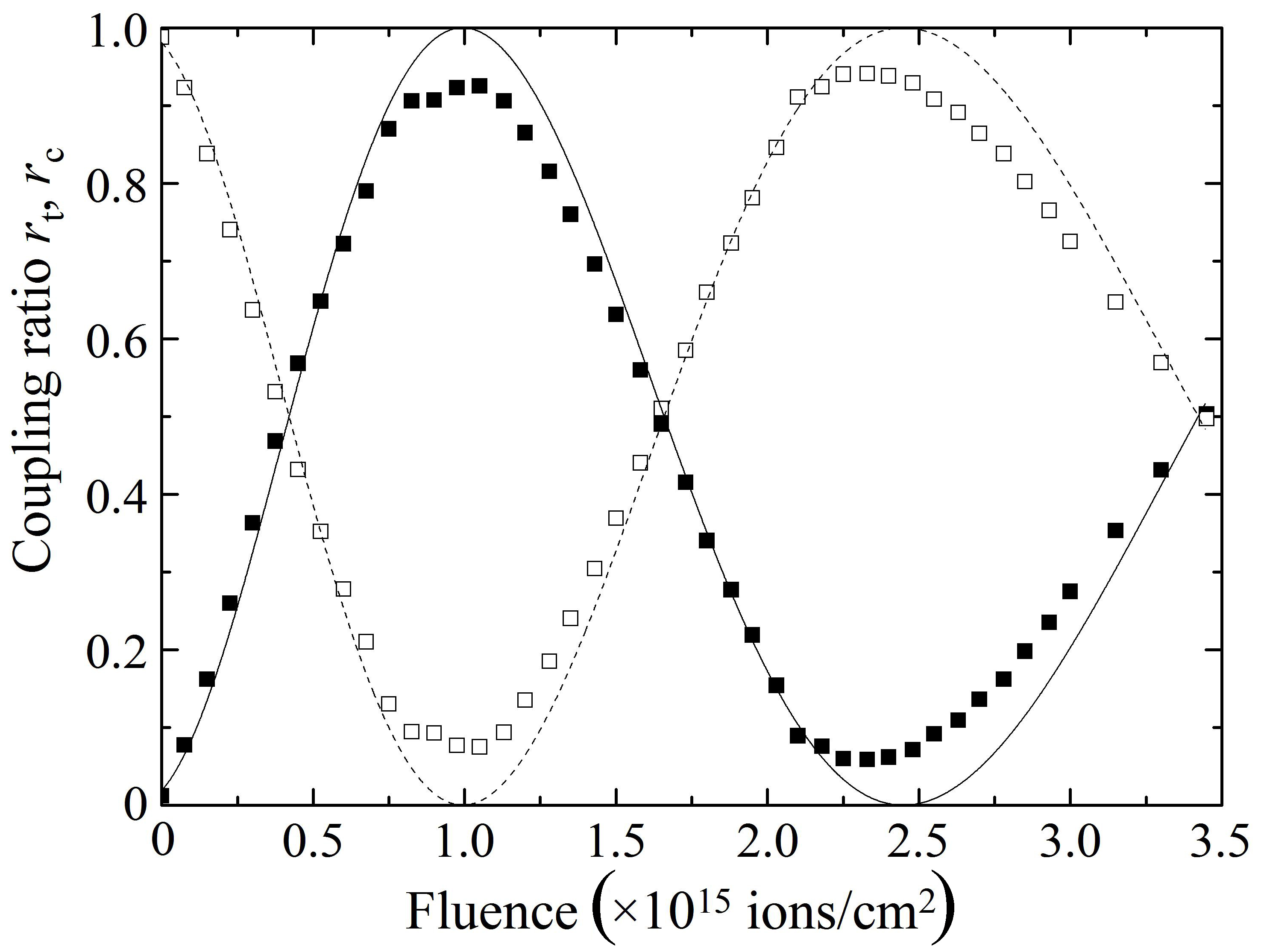
By implanting protons into a cladding in the coupling region of a directional coupler of the planar-lightwave-circuit(PLC) type at an acceleration energy that enables the protons to reach the center of the core, the coupling ratio of the coupler is changed periodically and continuously by increasing proton fluence. Figure 7 shows core patterns around the coupling region of a PLC-type directional coupler used for the experiment. The refractive index of the core is 1.45, and the relative refractive index difference is 0.32%. While the length of the coupling region z was set to be 5.0 mm, the spacing between the two cores (s) at the coupling region was either 3 or 15 ㎛. The couplers with s = 3 and 15 ㎛ are called samples A and B, respectively. A Pelletron accelerator at the National Institute of Advanced Industrial Science and Technology,Tsukuba, Japan was used to implant protons into the sample in a vacuum of 1 × 10⁴ Pa at room temperature. As shown in Fig. 7, P1, P2, and P3 stand for the optical powers of the input,through, and cross lights, respectively. To estimate the coupling ratio of each sample, the optical transmission ratios of P2/P1 and P3/P1 were measured during the proton implantation in the wavelength range from 1,530 to 1,570 nm by inputting unpolarized light into port 1 using an optical source and a spectrum analyzer.
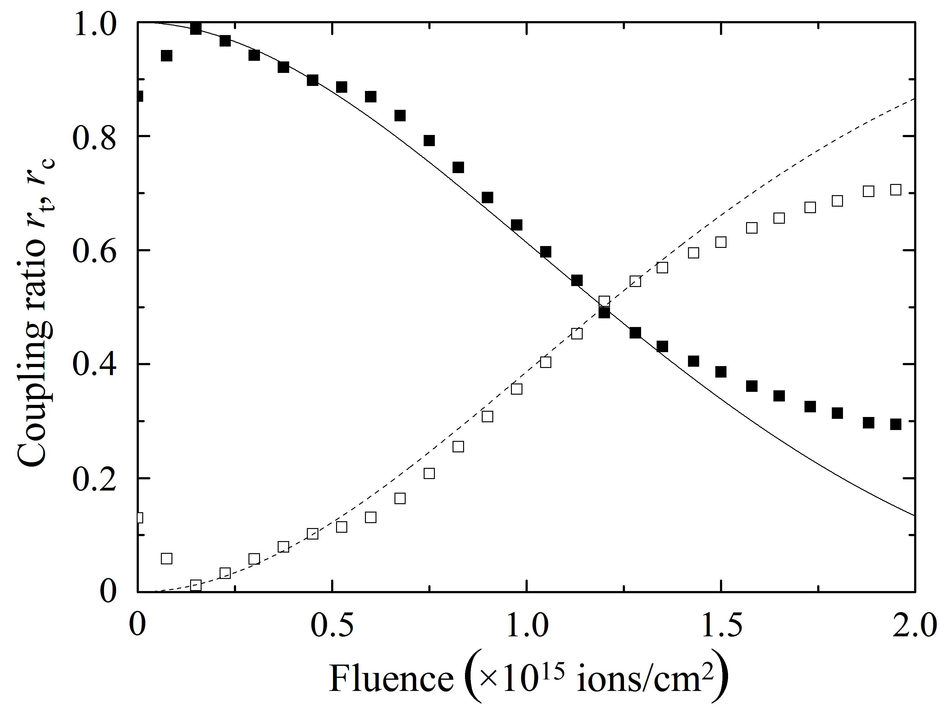
The closed and open squares in Fig. 8(a) denote the changes in the coupling ratios rt = P2/(P2 + P3) and rc = P3/(P2 + P3),respectively, as a function of proton fluence, measured at 1,550 nm for sample A, while those in Fig. 8(b) show the changes measured for sample B. The solid and broken curves in Fig. 8 are theoretical curves. In both samples A and B, rt and rc pe-riodically change their intensities with an increase in proton fluence so that rt shows maxima or minima at the fluences where rc shows minima or maxima, respectively, showing fairly good agreements with the theoretical curves. Therefore,Fig. 8 indicates that the implantation of protons at an appropriate fluence makes it possible to control the coupling ratio of a directional coupler and enhance optical coupling in the directional coupler that cannot transfer the propagating light properly owing to the very wide spacing between the two cores.
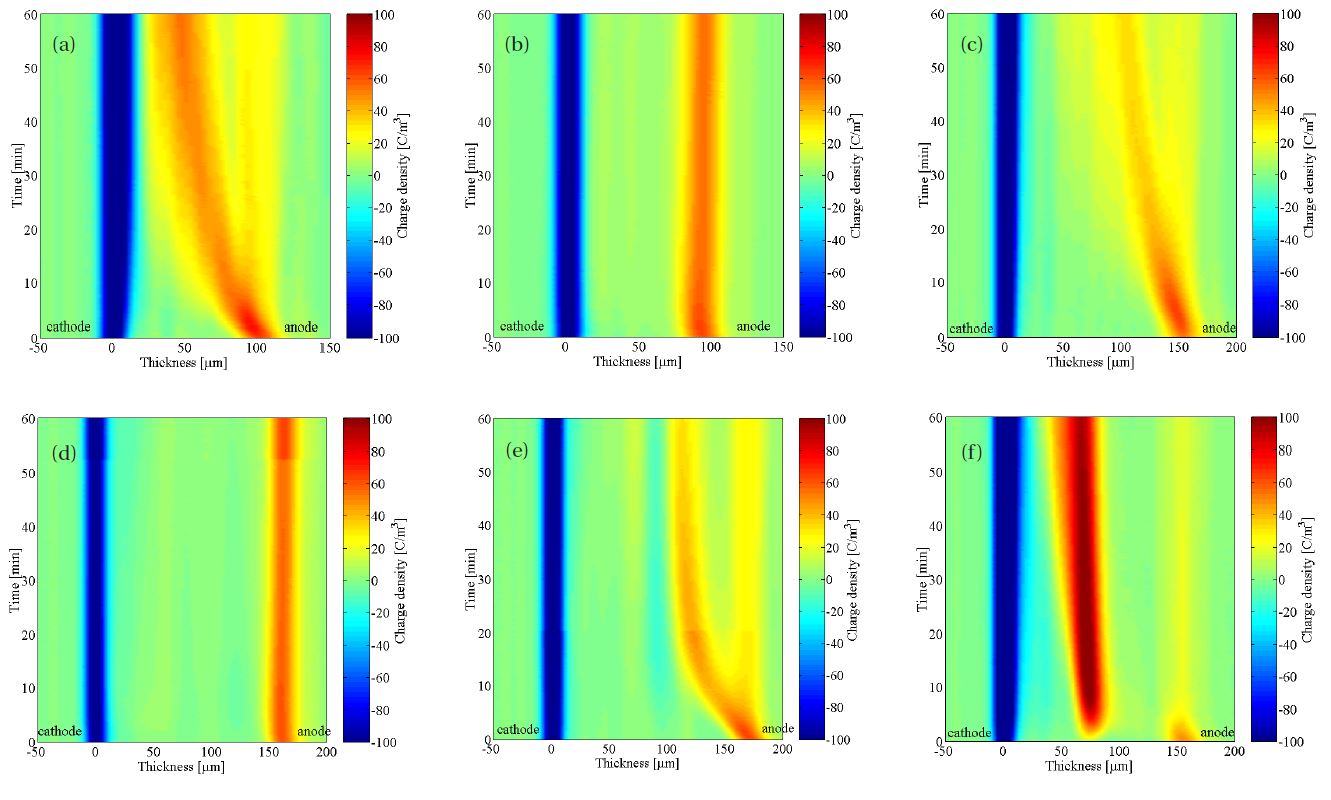
Various kinds of polymer nanocomposites are attracting much attention as new materials that are potentially applicable to electrical insulation in many parts of electric power apparatus. Among them, a composite consisting of LDPE and nm-sized magnesia (MgO) particles has been found by the author and his co-workers to be superior in various properties for electrical insulation of power cables. For conventional power cables insulated with XLPE, accumulation of space charge in the insulation is a matter of great concern, especially for their use in dc power lines. It has already been confirmed that space charge formation is significantly suppressed in the LDPE/MgO nanocomposite. Figure 9 shows an example of this pronounced effect of the addition of nm-sized MgO to LDPE on the suppression of packet-like space charge formation.The samples tested were LDPE without fillers (called Z)and its nanocomposite with near spherical MgO fillers having diameters of several tens of nm (called N). Furthermore, by pressing two sheets of Z, N and their combination at 100°C, a two-layered sheet was formed. Space charge distribution was measured for single-layered samples with a thickness of about 100 ㎛ and two-layered samples with a thickness of around 150 to 170 ㎛, by the pulsed electro-acoustic (PEA) method at room temperature during the application of a dc electric field of 100 kV/mm for 60 minutes. The progression of packetlike charge toward the cathode from the anode is limited within the region of Z as clearly shown in Fig. 9. In contrast to Z, the formation of space charge is suppressed drastically in the regions where the sample contains the MgO nanofillers as shown in Figs. 9(b), (d)-(f ).
Research topics done in the author’s laboratory, which he believes can contribute to green power technology, were briefly introduced.