In recent times, the occurrence of loss of offsite power (LOOP) events in nuclear power plants (NPPs) has increased, due to human error and/or component failures during the maintenance of the electric power equipment. These LOOPs have resulted primarily from combined causes of inadequate work management and human error. However, a program to prevent LOOPs through the well-prepared, systematic management of maintenance and other tasks for NPPs, including surveillance tests and outage maintenance, has not yet been developed. After recognizing this issue, Korea Hydro & Nuclear Power Co. (KHNP) initiated the development of a loss of voltage (LOV) monitor as a part of the NPP safety enhancement plan. Although there is a verified risk monitor, the outage risk indicator of NPPs (ORION), which evaluates outage risk, the LOV monitor is the first program to prevent LOOPs, because ORION cannot express an LOV condition as a warning.
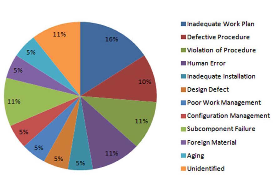
KHNP reported a total of 19 LOOP events to the regulatory organization, including a partial loss of the safety bus [1]. Ten of these events occurred from 2009 to 2012. LOOP events due to severe weather, such as thunderstorms, lightening, and strong winds were excluded in identifying the root causes because these are not controllable through human efforts. Thirteen events (68%) among the total of 19 events resulted from human-related errors. Only four events (21%) are related to the hardware failure such as component failure, foreign materials, and aging (see Fig. 1).
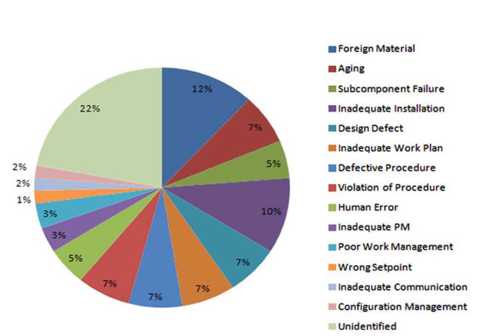
The root cause analysis was conducted again after the domestic LOOP events were combined with those from
the USA [2]. The results presented similarities in that a significant cause of LOOP events was created by human error, not by component failures (see Fig. 2).
2.2 Program Development Process
A starting point for preventing LOOPs is to control the loss of voltage (LOV)-initiating components. The LOV-initiating components are defined as those that can cause a loss of power in one or more trains. A low voltage relay for an LOV signal is actuated when the safety bus power is not provided by the preferred power supply (PPS). When an LOV signal is initiated, the circuit breakers for the normal and alternative power sources are opened and the emergency diesel generator (EDG) is started. If both EDGs and the final alternative AC diesel fail, a station blackout (SBO) will occur.
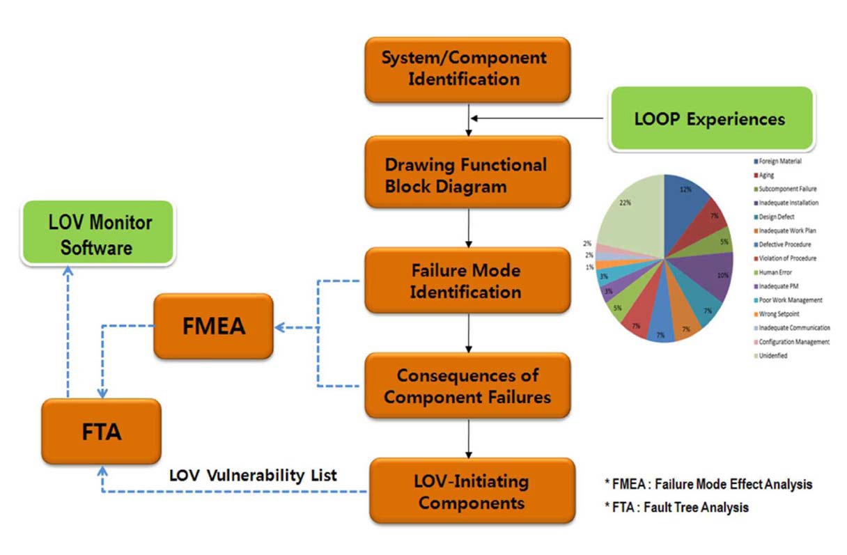
In the first development stage, design documents such as the system description, single line diagrams, and control logic drawings were reviewed in order to prepare a functional block diagram and identify the LOV-related components. After identifying these components in the system, the
failure mode and effect analysis (FMEA) was implemented; based on this, the fault tree analysis was conducted. Finally, the LOV monitor software was developed and a fault tree model was interfaced with the software for the LOV risk assessment during an outage. Figure 3 presents a schematic of the analysis process for the development of the LOV monitor system. It generally followed methods to monitor NPP risk from transmission grid conditions [3] and analyzed single point vulnerabilities in the switchyard [5].
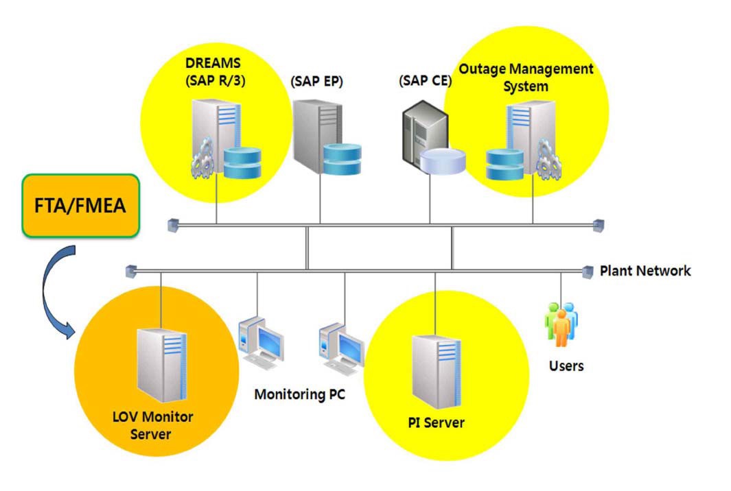
The LOV monitor software, which monitors the LOV status, provides a systematic tool for implementing work management related to the LOV during an outage. This tool is interfaced with the enterprise resource planning (ERP) database, outage management system (scheduling program), and a plant information (PI) server for users to analyze the LOV risk online. Figure 4 presents an overview of the development of the LOV monitor software.
KHNP is creating a list of LOV-initiating components, improving their reliability, and evaluating and monitoring the maintenance required to maximize plant safety. In order to achieve this, all replaceable subcomponents in the LOV
system must be considered when the LOV-initiating components are selected using the failure mode and effect analysis (FMEA). The NPPs of KHNP maintain detailed lists of the special components that could cause LOVs or LOOPs based on their design characteristics. Furthermore, special marks are attached to these LOV-initiating components in the field, and all work orders for these components are specially treated by the reinforced pre-job briefings. These efforts, and systems such as the LOV monitor, focus the current NPP activities on the switchyard and power block, and support operators in controlling the plant maintenance in order to enhance the safety of nuclear power plants.
Because an automatic system that can provide messages and alerts during the approval of work orders does not yet exist, it is difficult to manage and control, without delays, the work conditions of the components that could cause a loss of voltage. This leads to inadequate operator recognition of the changes in the system operating conditions during maintenance. For example, field components could be abruptly actuated by the unexpected isolation of components, incorrect arrangement, or incorrect manipulation, due to a lack of knowledge and/or human error. In addition, the time window of work orders for some components is not identical to the precise working time needed.
After the development of the LOV monitor is completed, a supervisory system for the maintenance of the LOV components during outages will be established. Therefore,
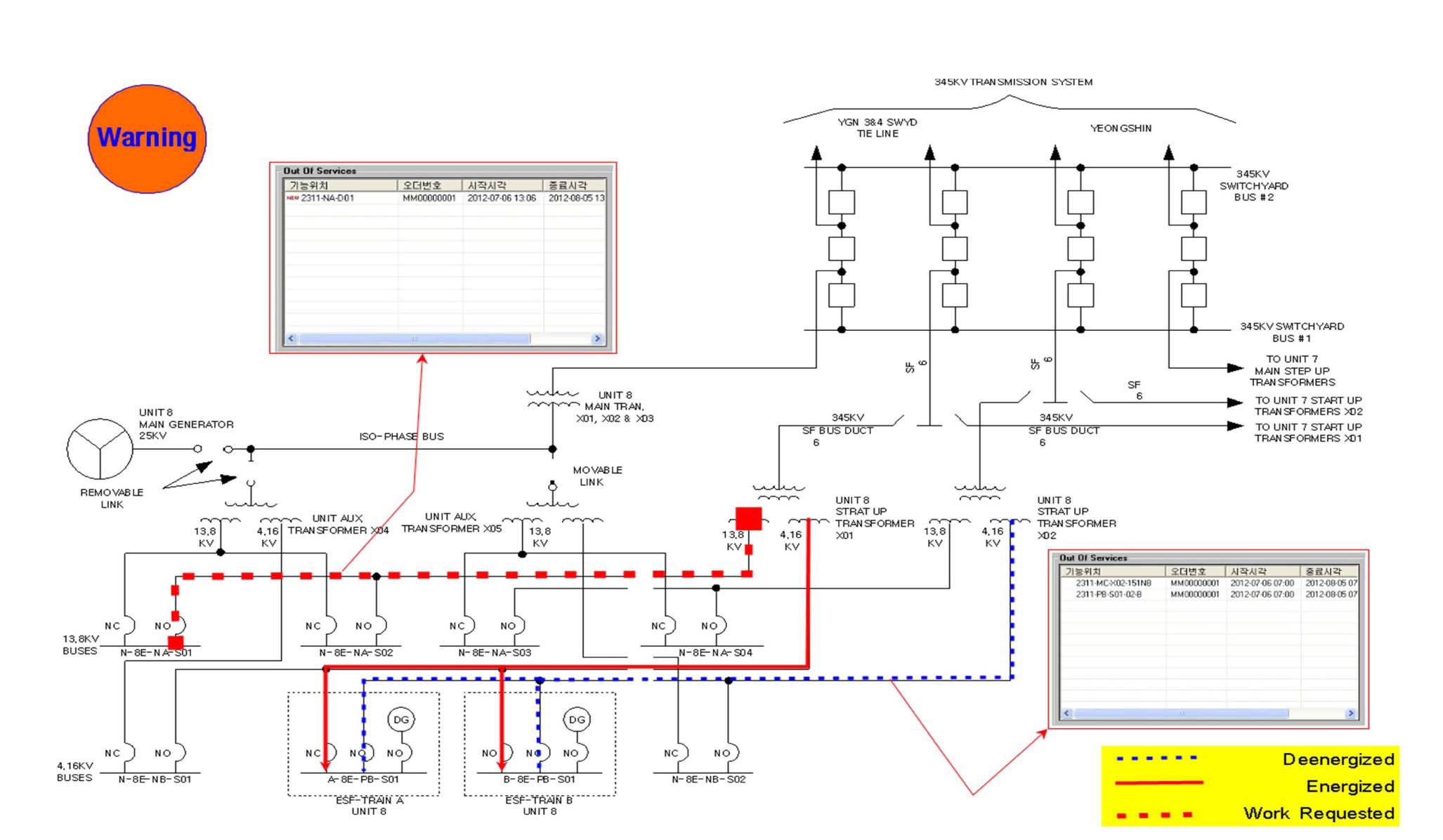
in the plant, the component states (primarily circuit breakers) related to the offsite power are monitored through the PI system. In addition, work orders are interfaced with the outage schedule management system, and they are collected and evaluated automatically from the ERP database. The operators assess whether the current work order could cause an LOV or not, if it is conducted through the use of an LOV monitor function for a one-click evaluation. The concept of the LOV risk monitoring system is presented in Fig. 5. Green means that both offsite power sources are provided. Yellow indicates that one train of offsite power is under maintenance. Orange (warning) means that one train of offsite power is under maintenance and a work order for the other train is issued within the same time window. Red (LOV) means that an operator pushed a monitor evaluation button and confirmed that an actual LOV will occur if he permits the work order.
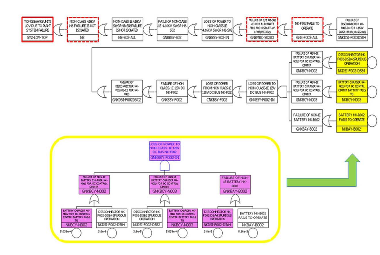
The fault tree presented in Fig. 6 indicates one case among the thousands of failure or out of service combinations that can result in an LOV. If a non-1E 4.16 kV power bus is energized and has a fault (e.g. an unblocked work order due to human error) when non-1E 125 VDC power (NB) bus maintenance is in progress, this bus fault is propagated to the start-up transformer, which leads to the opening of the switchyard circuit breaker, which results in an LOV on the safeguard bus.
This fault propagation occurs because the related circuit breaker (NB S02-03) cannot be opened due to a lack of control power to isolate the bus fault.
KHNP is developing an online risk assessment program (LOV monitor) that focuses on a loss of voltage on the safeguard bus. This new program can support maintaining plant safety by preventing the loss of offsite power that can be initiated from the LOV condition. In addition, outage schedule delays resulting from the LOV event are prevented. In terms of technical benefits, the loss of voltage or loss of offsite power caused by human error and inadequate work management can be prevented, because operators can evaluate the LOV-related risk more easily within the limited time before permitting the work order in progress. This program may be called integrated online supervisory software, because it is interfaced with both the PI system and the ERP database containing all outage work orders. This program will be applied in the priority determination of plant preventive maintenance, design improvements, and optimization of equipment operation, because the vulnerabilities that can cause the loss of voltage can be evaluated quantitatively.
3.2 Achievements and Conclusion
Because the LOV monitor raises the alarm about the power loss of one train of the safety bus before the power loss of the other train occurs, a loss of offsite power (LOOP) due to inadequate work management during an outage can be prevented. Seven events, which were related to the human error, inadequate work plan, work management, and system configuration management, among a total of 13 LOOP events (including partial loss cases) in domestic NPPs could be avoided by using the LOV monitor. Approximately 50% of loss of offsite power events, based on historical data, may be prevented in the future using this LOV monitor. Therefore, for safety improvements of plant operation and maintenance, the work management reinforcement through the development and operation of an LOV monitor may be a more cost-effective method than massive design changes or system improvements.
When the probabilistic risk assessment (PRA) model of the domestic plant that experienced the station blackout in 2012 was used for the safety analysis of this LOV prevention program, it was evaluated that approximately 27% of core damage frequency would have been reduced with a decreased LOOP initiating event frequency. This frequency reduction is calculated by the assumption that one train loss of the safety bus (partial loss case) is regarded as a LOOP event.
In conclusion, the establishment of the maintenance program including the operation of an LOV monitor for the offsite power system is expected to contribute to strengthening risk management and safety culture, as well as preventing unexpected loss of offsite power events in nuclear power plants.