TerraPower has its origins in conversations between Bill Gates, Nathan Myhrvold and Lowell Wood in 2007 where they discussed what could be done to raise the standard of living on a global scale. They concluded that energy in its various forms is essential to progress and new 21st century technologies/skills will lead to great improvements in our energy infrastructure. They mathematically analyzed all energy generation technology options from a total system perspective and concluded that raising the standard of living of all people will require global utilization of nuclear energy in a suitable form that addresses the existing challenges of fuel availability, cost, proliferation and waste production. It was from this meeting that TerraPower was born with the guiding objectives to minimize energy costs, assure availability of energy to all nations, maximize inherent proliferation resistance, offer new options for nuclear waste and achieve manifest safety. The company started out with a clean slate and studied all of the proposed reactor concepts to date. After a thorough evaluation, TerraPower determined that a sodium cooled breed-and-burn concept, which we call a TWR, best satisfied all of the guiding objectives.
A TWR is a class of reactor that is uniquely designed to operate indefinitely after a startup period using only natural or depleted uranium (DU). The waves that breed and deeply burn fissile nuclides in-situ travel relative to the fuel and provide the possibility for very long core life (~60 years) plus additional characteristics not achieved in typical fast reactor designs. This long core life allows for significantly higher fuel utilization, up to about 30 times greater than light water reactors (LWRs). Coupling that with global reserves of uranium, TWRs offer an inexhaustibly renewable energy resource for the entire human race1,2. Because of its high breeding ratio, the TWR core produces enough extra fuel to start other TWRs without requiring any additional fuel enrichment. Subsequent generations of TWRs are started with discharged fuel from previous generations. Furthermore, TWRs require no chemical reprocessing capabilities with element separation and eventually eliminate the need for enrichment. Thus nuclear energy can be expanded globally without the fuel cycle infrastructure associated with producing weapons materials. This allows a clear separation in the international community of those countries pursuing peaceful uses of nuclear energy from those who are not. Therefore, despite the technical challenges of TWR development discussed in Section III, TerraPower has determined that the benefits offered by the reactor justify the effort required to pursue a comprehensive development and deployment program with the goal of having an operating TWR by the early 2020s.
2. BACKGROUND TO TWR DEVELOPMENT
The first known proposal for a fast reactor design that could sustain a breed-and-burn condition using only natural uranium or depleted uranium as fuel was made in 1958 by Feinberg3 and a number of studies followed. These studies can be categorized into two classes of cores. The first class includes standard fast reactor cores with conventional assemblies and fuel shuffling during reactor shutdowns. This class includes the concept of a Fast Mixed Spectrum Core (FMSR) evaluated at BNL4 in collaboration with MIT5. Both sodium and gas cooled FMSR versions were explored in these studies. A lead cooled breed and burn concept was developed by Toshinsky6,7 and more recently, a gas cooled breed and burn concept was studied by Yarsky8.
The second class of TWRs involves the cores where fuel remains static (i.e. no shuffling) and the wave travels relative to the fuel. This concept was introduced by Teller9 for a gas?cooled thorium breed and burn reactor and studied further by Sekimoto with the CANDLE (Constant Axial shape of Neutron flux, nuclide number densities and power shape During Life of Energy producing reactor) concept10. CANDLE concepts were studied with lead coolant11 and with pebble bed fuel12. A more recent study at General Atomics focused on the helium-cooled Energy Multiplier Module (EM2) with plate type carbide fuel and silicon carbide structural material13. In addition to these studies, several papers have been published on the mathematical theory of a nuclear breed and burn wave moving through the static fuel14,15,16.
All the studies above focused primarily on the neutronic aspects of the core performance without considering all engineering and fuel performance limits. In 2008, Terra-Power launched an effort to develop the first practical engineering embodiment of a breed-and-burn fast reactor considering all the engineering limits to produce a design concept now known as the TWR17. The first studies focused on the shuffle-free concepts where the wave travels through fixed fuel. While this class of TWR has the advantage of not requiring any fuel shuffling and appeared attractive from a practical point of view, it suffered from a poor neutron economy due to neutron leakage into the fission products behind the wave and therefore required very high burnup to breed enough plutonium to sustain the wave propagation. Practical TWR designs were hampered initially because of conflicting demands made by the orientation of coolant flow and control systems and very high peak burnup requirements to breed sufficient plutonium to sustain wave propagation. After exploring various design options and core geometries, TerraPower core designers identified a “standing wave” cylindrical geometry variant of the TWR as the most promising practical design. The design underwent several iterations1,18,19,20 between 2008 and 2012. This paper describes the latest version as of December 2012.
Section I discussed a number of significant advantages of TWRs over traditional fast breeder reactors and LWRs. As with any reactor concept, there are also drawbacks or challenges that need to be overcome before the TWRs can be successfully developed and deployed. None of the earlier studies of breed and burn concepts discussed in Section II have addressed all of these challenges in a systematic manner to assure that the TWR core design can satisfy all neutronic, thermal hydraulic and mechanical limits. This section will discuss the key challenges of a TWR core design and their interrelationships. The key solutions to these challenges, which in a few cases require innovative approaches, are listed in Section IV.
The TWR active core volume is significantly larger than for a conventional fast reactor in order to minimize neutron leakage for optimal plutonium breeding. To be able to operate in an equilibrium cycle feeding only depleted uranium assemblies, the smallest core radius/height is approximately 2m/2.3m for a metal fueled TWR core. Therefore, a significant increase of core leakage by reducing the core height is not an option for TWR cores. Other traditional design features, such as axially interspersed layers of seeds and blankets are also not effective for TWRs because they only work at low burnup (e.g. before enough plutonium breeds into the blanket layers and the blanket becomes fissile driver fuel). Zirconium hydride and technetium layers are also not effective because they soften the neutron spectrum, which reduces the breeding ratio and increases the minimum burnup necessary to sustain wave propagation.
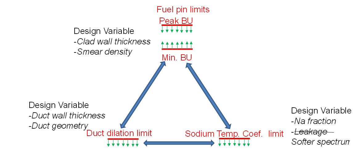
As indicated in the figure, the fuel burnup needs to be above the minimum peak burnup and below the thermomechanical
peak burnup limit (which is determined by the cladding strain from irradiation or thermal creep). The peak burnup limit can be increased by increasing cladding thickness. However, a larger cladding thickness results in larger parasitic losses that lead to a higher minimum burnup. A more effective approach to increase the peak burnup is to reduce the fuel smear density to provide more space for fission product swelling and reduce cladding stress. However, pins with a smaller smear density have less fuel which leads to a higher minimum peak burnup and more importantly to a more positive sodium temperature coefficient due to the larger amount of sodium bond.
The duct dilation limit is determined by the gap available between the ducts. It is desirable that at the end of assembly life, the duct walls of adjacent ducts do not come into contact so as to avoid excessive withdrawal and insertion forces during fuel shuffling. One possible design approach to reduce duct dilation is to increase the duct wall thickness. However, the larger amount of steel in the core leads to higher minimum fuel burnup, which reduces the fuel pin design window. The other design variable to address the duct dilation issue is to increase the gap between the ducts to provide more space for duct bulging. This leads to more sodium in the core which makes the sodium temperature coefficient more positive.
As discussed above, larger cores typically have a positive sodium temperature coefficient, which is kept in check through increased leakage. However, the very low leakage needed to support breed and burn operation at reasonable minimum burnup precludes this option for TWRs. Therefore, minimizing the sodium fraction in the assembly is the main remaining design variable to keep the sodium temperature coefficient within acceptable bounds. This leads to different fuel assembly designs with the absence of a sodium bond and innovative duct designs that allow a relatively small gap between assemblies.
The discussion above shows that the design limits are co-dependent on assembly design variables. Also, because of the high minimum peak burnup needed to support breed and burn operation, the design window for TWRs is tight and the TWR design that satisfies all of these limits is the central challenge facing the TWR core designer and will require innovative approaches.
4. KEY DESIGN FEATURES TO ADDRESS TWR DESIGN GRAND CHALLENGE
Given the core design challenges described above, traditional SFR fuel assembly designs do not offer an acceptable solution for a TWR operating on DU (designated TWR-C); innovative solutions are needed in order to satisfy all of the relevant limits. This section highlights the key innovative features of TWR-C that make it possible to overcome the design challenges and offer a promising path forward.
The large positive sodium temperature coefficient is addressed through two main design approaches:
Minimization of the amount of sodium in the core through: (a) the use of a tight pitch hexagonal lattice to keep the amount of coolant between the pins as small as possible while keeping an acceptable pressure drop, (b) the minimization of the gap between the ducts while providing enough space for duct dilation and swelling to maintain acceptable assembly withdrawal forces, and (c) the design of a fuel pin without a sodium bond.
Maximization of the reliance on other negative reactivity feedbacks through: (a) the use of a load pad design and core restraint system that achieves a large negative core radial expansion reactivity feedback effect, (b) the use of a Control Rod Driveline (CRD) and upper internal structure design to maximize the negative CRD reactivity feedback effect, and (c) the use of special passive absorber insertion modules that reduce reactivity upon temperature increase by passive means.
To accommodate high peak burnup, the TWR-C fuel pins have the following features:
Significantly reduced smear density to provide more space for accommodating fuel swelling and mitigating FCMI. Metallic fuel pins have traditionally had smear densities of ~75% to allow for sufficient gas-bubble growth dominated by fuel swelling and gas release without exerting unacceptably high contact pressure on the cladding. TWR pins will have significantly lower smear densities in order to provide more space for additional fission gas release and solid fission product swelling.
Fuel pin venting. Fission gas release prevents gas pressure buildup in the pin and thus reduces the stress and strain on the clad.
The above strategies of low smear density and fuel pin venting also mitigate the consequences of high dose on irradiation creep-driven cladding strain since they eliminate the stress from internal gas pressure and reduce the creep strain from FCMI. More importantly, TerraPower is developing advanced ferritic-martensitic steel with an optimized microstructure for the clad that is expected to exhibit very low void swelling rates and irradiation creep up to 600 DPA. The strategies outlined above, lead to a pin design that is very different from traditional metallic fuel pins for fast reactors. The specifics of the innovative pin design are proprietary and have not been released in publicly available literature.
In addition to the advanced fuel pin design, TWR-C assemblies also require innovations in the duct to overcome the large wall dilation at high fluence. The typical approach of a thickening the duct to mitigate irradiation creep induced duct dilation would have a large neutronic penalty resulting in an unacceptably high minimum peak burnup. To address this challenge an innovative duct design has been developed at TerraPower that exhibits small duct dilation at acceptably small wall thicknesses compatible with neutronic requirements.
TerraPower performed extensive neutronic, thermal hydraulic, mechanical and fuel performance analysis of the TWR-C core with innovative fuel assemblies and confirmed feasibility of operation on depleted uranium in equilibrium with minimum peak burnup of 30% and peak DPA of 600. Although these analyses showed that TWR-C is feasible, the innovative features introduced to overcome the challenges will require significant development. The key areas of development include:
performance of innovative low smear density metal fuel pins with burnup levels of ~30% including the reliability of the mechanical bond,
clad swelling and irradiation creep data up to a peak dose of 600 DPA,
duct swelling, irradiation creep and bowing performance up to a peak dose of 600 DPA,
manufacturability of innovative duct,
validation of radial expansion reactivity feedback for the large TWR core with new ducts,
passive absorber insertion module testing and validation of its performance in the core,
validation of the breed-and-burn process and fuel management tools for the TWR.
In addition to the significant development and irradiation testing program, which is required to address these areas, some of the features (specifically those under the last three bullets) will have to be tested in a large prototype TWR. The TWR-P plant described in the next section is being designed for precisely this purpose.
5. DESCRIPTION OF TWR-P TECHNOLOGY
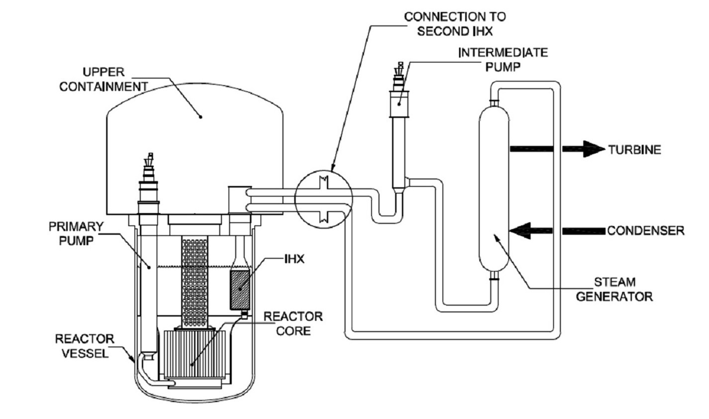
TWR-P is a 1475MWth/600MWe gross liquid sodium cooled, fast neutron spectrum reactor that uses U-10%Zr metallic fuel with HT-9 ferritic-martensitic stainless steel clad. The 4m diameter, 5.5m tall cylindrical core sits near the bottom of a 13.3m diameter, 17.65m tall reactor vessel which is enclosed within a guard vessel. This pool-type configuration has no radial piping penetrations through either vessel so the risk of loss of coolant accidents is eliminated. Additionally, the large volume of sodium acts as a huge heat sink, so transients are much slower, operators have much longer to respond to off-normal events and the overall safety performance of the plant is significantly enhanced when compared to currently operating LWRs.
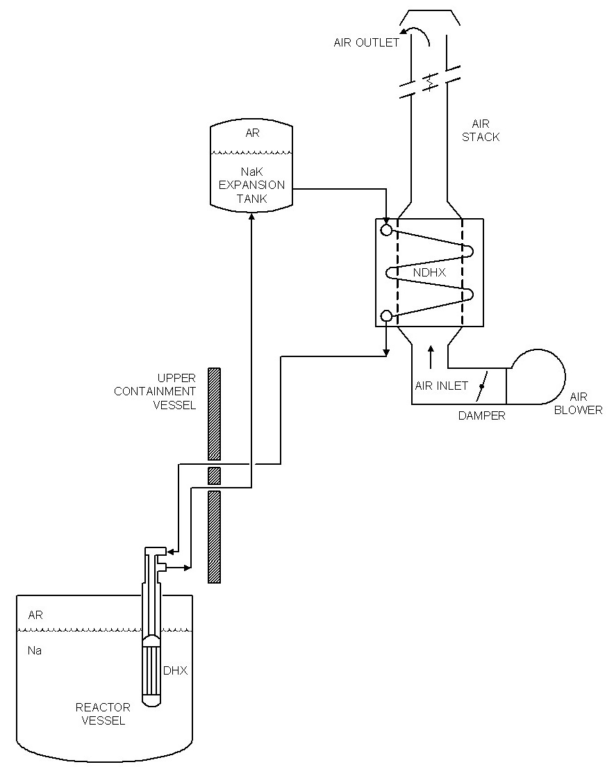
TWR-P has two sodium filled intermediate heat transport loops which transport the heat from the primary sodium coolant in the reactor vessel to the steam generators outside of containment. Ultimate conversion of heat to electricity is by a conventional Rankine steam cycle with superheat. For emergency decay heat removal, the plant has four Direct Reactor Auxiliary Cooling System (DRACS) loops, each of which is capable of removing enough heat to protect public health and safety. These NaK (sodium-potassium eutectic) filled loops are completely passive and require no electricity to activate or operate.
TWR-P is a multi-mission reactor. In addition to demonstrating the breed and burn process in feed assemblies in a flux profile and shuffling scheme similar to that of TWR-C, it will also validate overall core performance and demonstrate key prototypic plant equipment. TWR-P will serve as the last step of the fuel/material qualification program and provide the technical, licensing and economic bases for follow-on TWR plants. To complete these missions, the plant can accommodate lead test fuel assemblies, has limited post-irradiation examination capability on-site and incorporates first-of-a-kind instrumentation and maintenance considerations.
5.1 Core Description and its Key Characteristics
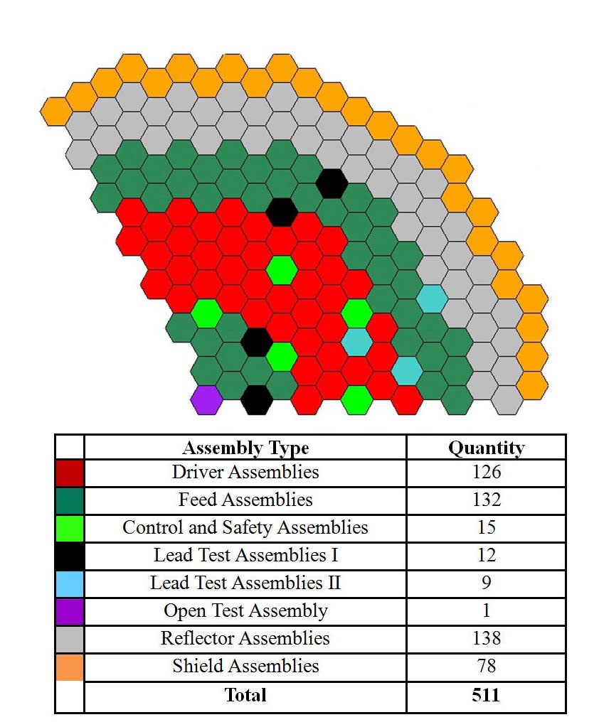
The TWR-P core was developed to accomplish four key mission goals: (1) demonstration of TWR-C core fuel management, (2) qualification of TWR-C fuel assemblies, (3) validation of core radial expansion reactivity feedback and effectiveness of the core restraint system, and (4) validation of passive reactivity feedback devices. The core map is shown in Fig. 2.
The TWR-P core employs enriched fuel assemblies (driver assemblies) with sealed sodium bonded metallic
U-10Zr fuel pins having 70% smear density, for which data and experience is available. To achieve flux profile and power and temperature gradients similar to those of TWR-C and reproduce prototypical power histories of breed and burn assemblies, the core also employs feed fuel assemblies made of depleted uranium. These fuel assemblies also have U-10Zr metal fuel with 70% smear density. Both the driver and feed fuel assemblies form a host core to provide a prototypical environment to that in the TWR-C core, including the shuffling scheme. The host assemblies will be driven to much smaller burnups and fluences than the TWR-C assemblies. To support the high peak burnup and DPA levels for TWR-C fuel, the TWR-P host core will be used to qualify advanced TWR-C fuel assemblies and fuel pins at full scale. The lead test assemblies (LTAs) will have their own shuffling scheme and positions and will be of two types ? (1) prototypical TWR-C design (Type I) with design parameters identical to those of TWR-C and (2) assemblies for accelerated burnup accumulation (Type II) that will be operated at higher power density. Some of the LTAs will simulate the expected history of TWR-C fuel: they will start as feed assemblies to be shuffled during outages into the high power density zone after they have accumulated sufficient dose and corresponding conversion to plutonium. The core has two rows of reflector assemblies made of steel rods and 1 row of B4C shield assemblies. Finally, the core also provides a central high flux position for either a Material Open Test Assembly (MOTA) or a Fuel Test Open Assembly (FOTA) with online in-core monitoring capabilities.
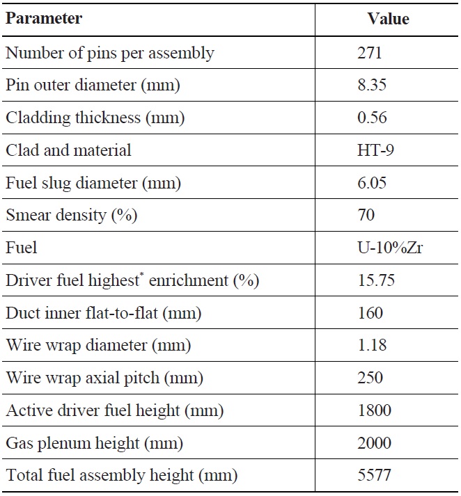
The host fuel assemblies have 271 metallic fuel pins in a hexagonal duct. The fuel pins have U-10%Zr fuel with a sodium bond. Both the feed and driver assemblies have identical dimensions, but the driver assemblies have different enrichments. The key assembly parameters are given in Table 1.
The primary reactivity control for the reactor is provided by twelve movable primary control rods. In addition, the TWR-P core has three safety assemblies that provide redundant shutdown capabilities. These safety assemblies are fully withdrawn above the core during reactor operation and are required solely for shutdown capability in case of an extremely unlikely failure of the primary control assemblies to shutdown the reactor. Both the primary control and safety rod assemblies contain 19 sodium-bonded and vented B4C pins in an inner round duct. The round shape of the inner duct in combination with rod pin array geometry provides faster scram time and is less susceptible to jamming during seismic events. The axial movement of control and safety rods is accomplished by the Control Rod Drive Mechanisms (CRDMs) located on the reactor head rotating plug. The CRDM elevating drives utilize a collapsible roller nut arrangement similar to the very successful design used at the Fast Flux Test Facility and designed and tested for the Clinch River Breeder Reactor. The primary and safety rod absorber bundles can be detached so that their drivelines may be lifted up above the reactor core face to permit plug rotation.
In a breed-and-burn reactor, individual fuel assemblies produce varying amounts of power based on burnup and initial fissile loading. As the fertile assemblies build fissile inventory and come to power, their cooling requirements will increase. Therefore, the core design must ensure assembly power-to-flow matching throughout the core life. This is achieved through fixed orifices and a strategic shuffling scheme that maintains a stable radial power profile through the core life. The TWR-P core has 20 flow zones to match power distribution between the lowest and highest power. The flows in each zone are set by fixed orifices located in the assembly receptacles, which are positioned between the lower and upper core support grid plates through restraint lands that mate with seats in the grid plates.
One of the key challenges for a breed-and-burn reactor is to identify a fuel shuffling and orificing strategy that ensures the power to flow ratio remains within acceptable bounds by not exceeding peak inner cladding temperature (PICT) limits. The following constraints are imposed on the fuel management scheme in TWR-P:
1. Reactivity swing between cycles less than 5$
2. Cycle length is greater than 1 year.
3. Peak burnup of DU feed and driver assemblies is less than the 15% FIMA burnup limit.
[Table 1.] Key TWR-P Standard Assembly Parameters

Key TWR-P Standard Assembly Parameters
4. 2-sigma PICT <625℃ and below burnup-dependent PICT limit to keep clad thermal strain below 1%.
5. Difference between outlet temperatures of any two adjacent assemblies is below 50℃ in power producing zone and 110℃ on the boundary between power producing zone and peripheral zone to minimize thermal striping.
6. Maintain similar shuffling strategy as in TWR-C to closely reproduce breed and burn histories of feed, fissile and lead assemblies to achieve good representation of power histories, fluxes and flux gradients for best full scale assembly and core performance validation.
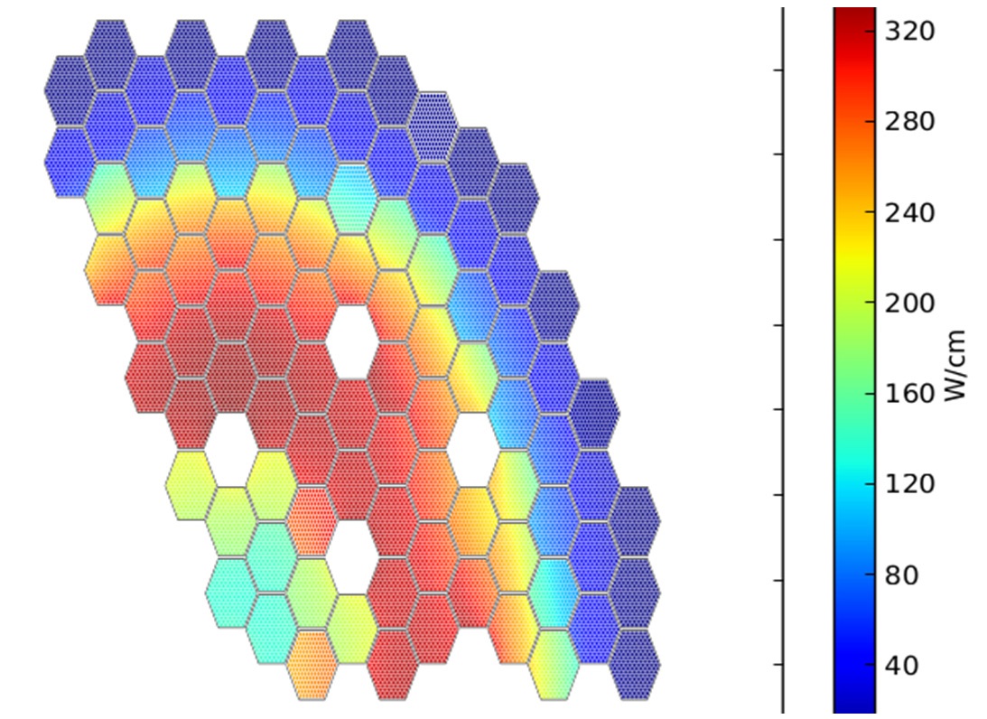
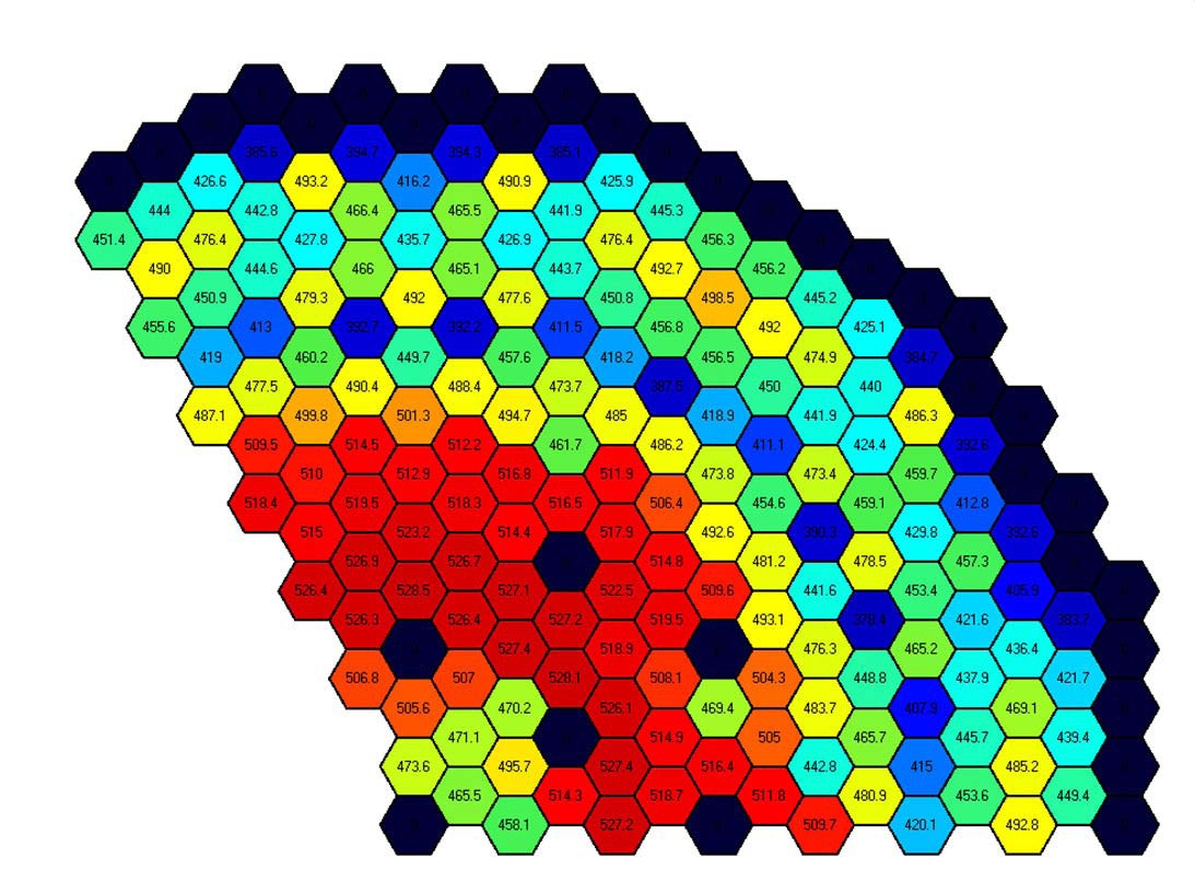
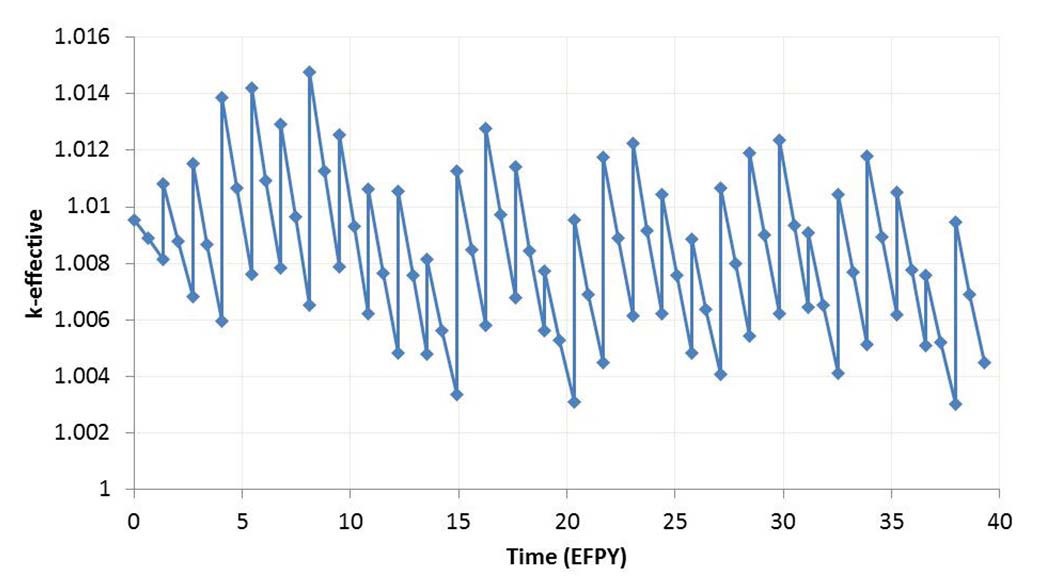
Neutronic and fuel management analyses were performed using the in-house developed Advanced Reactor Modeling Interface (ARMI), based on neutronic modules MC**2-222 and REBUS-PC23. Fig.2 shows that reactivity can be maintained within prescribed limits over the 40-year core life. The cycle length is 495 EFPDs and during each cycle there are 42 driver assemblies at 15.75% enrichment/12 feed DU assemblies loaded and 54 assemblies discharged. The maximum excess reactivity is 2.1$, which is below the target of 5$. Fig. 2 plots pin linear heat rate throughout all fuel assemblies at the core midplane. It can be observed that the feed assemblies with DU on the core periphery have very low power. Power in the center of the core is also relatively low because it comes from feed assemblies that bred in some plutonium and were shuffled to core central position. This power distribution closely simulates power profile in the TWR-C core. Fig. 4 shows that core outlet temperature profile is relatively flat confirming the effectiveness of orificing zones that match power to flow. Since the orifices are fixed in the receptacles below the core grid plate, it is necessary to maintain core power distribution near that shown in Fig. 3 over core life. This is achieved through a carefully designed fuel management shuffling strategy. Thermal hydraulic analysis using COBRA-4i-MIT24 confirms that the 2-sigma PICT remains below 625℃ over the core life.
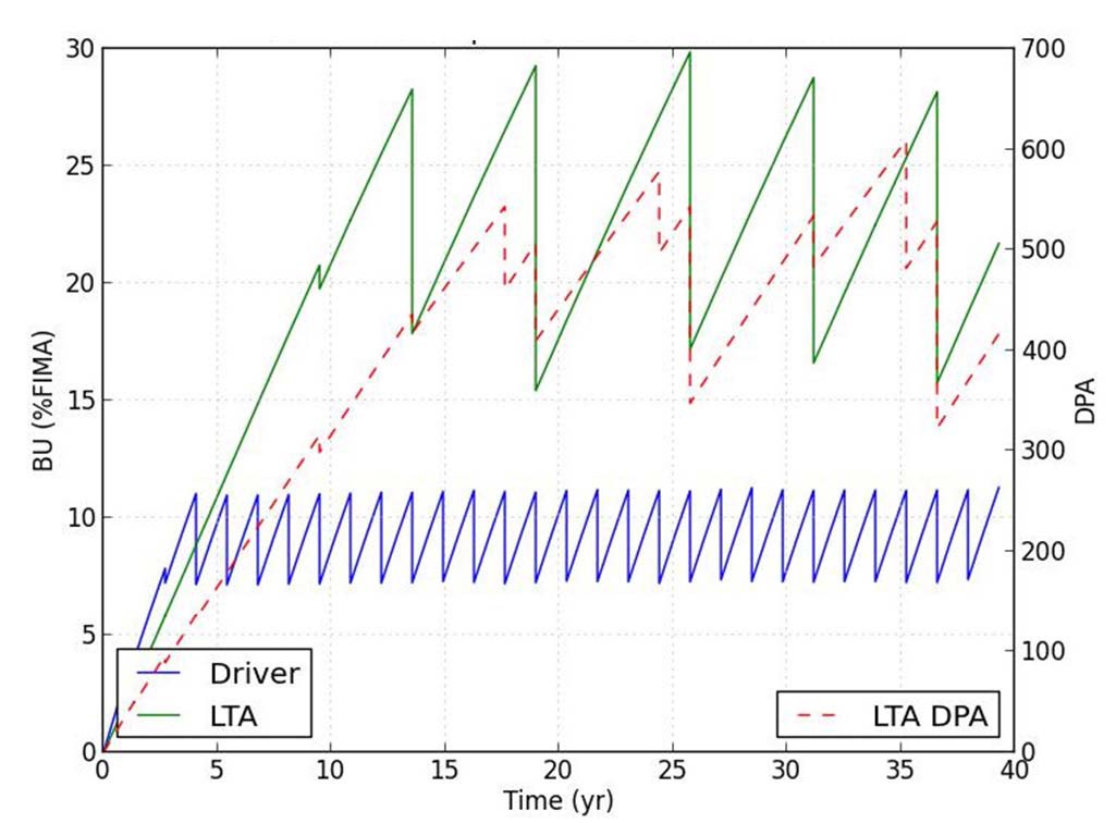
Fig. 5 plots the peak burnup for the driver pins, LTA pins and peak DPA for the LTA pin cladding. The values
are peak values over the whole core, hence there is no local correspondence. It can be seen that the driver pins of the host assemblies do not exceed peak burnup of 11%
while the LTA pins reach the target peak burnup of 30% and peak dose of up to 600dpa.
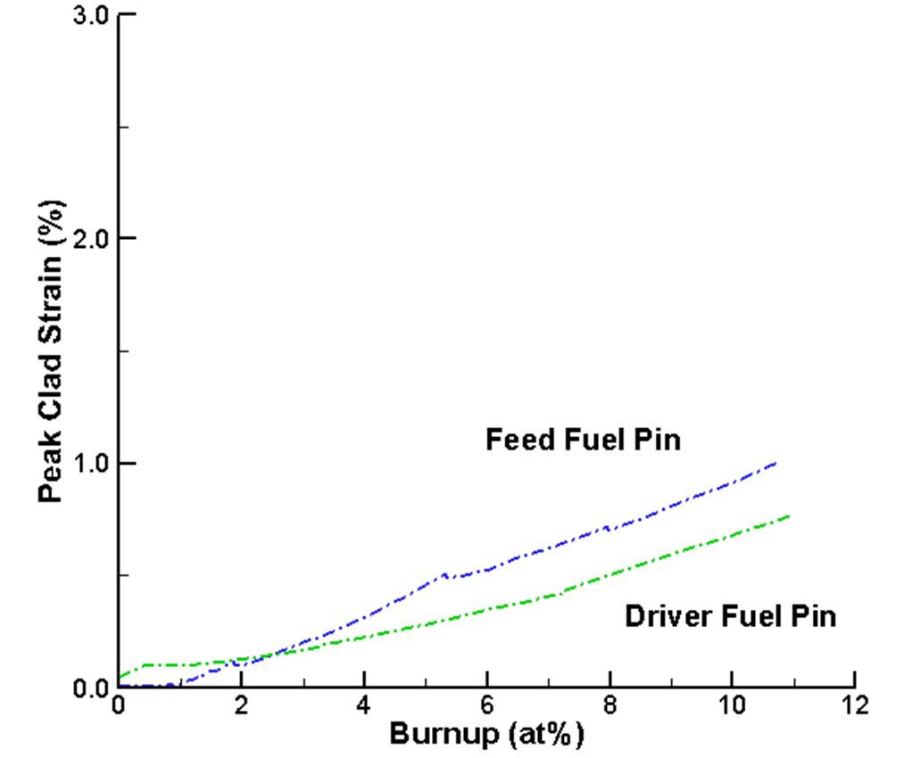
Fig. 6 plots peak cladding strain for the driver and feed pins of standard fuel, using in-house fuel performance code ALCHEMY. The peak strain is driven by FCMI creep and remains well below the 3% limit. The thermal creep component remains well below 1% limit. Similar analysis for the vented LTA pins showed that 3% cladding strain limit can be met. Also, the duct mechanical analysis confirmed that the combined void swelling and irradiation creep in the ducts remain within acceptable limits.
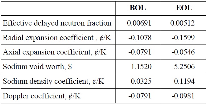
The reactivity coefficients of the TWR-P core are summarized in Table 2. They are comparable to those of other metallic fueled sodium cores. The sodium temperature coefficient and void worth have small enough positive values to ensure a large net negative temperature coefficient. The relatively small sodium temperature coefficient is due to the significant amount of fissions from U-235, which has a smaller increase of fission/capture ratio upon spectrum hardening than does Pu-239. Section V.C shows that the TWR-P core having these reactivity coefficients can achieve inherent shutdown even in beyond design basis accidents without a reactor scram.
[Table 2.] TWR-P Reactivity Coefficients.

TWR-P Reactivity Coefficients.
The TWR-P plant is comprised of approximately forty distinct systems. These systems are broken into two major categories: the Nuclear Island (NI) systems and the Balance of Plant (BOP) systems. The NI systems include the Reactor Core System and all of the systems that directly support operation of the core. Two key NI systems are the Reactor Main Heat Transport System (RMHTS) and the Steam Generator System (SGS). The RMHTS transports the heat generated in the core to the SGS where the heat is used to produce steam. Other NI systems include the Containment System, the Reactor Decay Heat Removal System, the Plant Protection System (which provides automatic reactor shutdown, containment isolation, and post accident monitoring capabilities), systems for maintaining sodium coolant purity, and systems for providing and processing argon gas which is used as a cover gas blanket wherever there is a free surface in the liquid metal systems. Because of the limited space available in this paper, only major systems will be briefly described.
Each Intermediate Heat Transport System (IHTS) loop consists of two parallel IHX units, the IHTS pump, and the piping that connects them to the Steam Generator System (also shown schematically in Fig. 7). The IHTS pumps will also be centrifugal pumps but because the IHTS pressure drop is very low, a more conventional single stage design is adequate. The IHX is of typical tube and shell design, although TerraPower is also studying the use of more innovative compact heat exchangers to reduce IHX size and primary-to-intermediate temperature difference.
and a prototype unit was subjected to extensive sodium testing. Change planned for implementation on TWR-P includes appropriate scaling (the design heat load for the TWR-P units is slightly lower than for the ALMR units).
Although the steam generators will be designed, fabricated and operated to very stringent requirements, the potential for a small leak in a tube cannot be completely eliminated. A small amount of leakage can be tolerated. However, it must be detected quickly so that action can be taken to prevent the failure from growing and possibly propagating to adjacent tubes. The TWR-P design incorporates both hydrogen detectors and an acoustic leak detection system for this purpose. Hydrogen detectors have been used successfully in many previous plants. While acoustic leak detection is relatively new, it has been the subject of considerable development, design and testing work.
In spite of the high quality of the steam generator and the implementation of sensitive leak detection equipment, the potential for a relatively large sodium-water reaction event in the steam generator will be considered as a design basis event. In order to protect the steam generator shell and IHTS (including the IHX) from over-pressurization, large rupture disks with a relatively low rupture pressure will be connected to the cover gas space at the top of the steam generator. In case of a large sodium-water reaction event, this rupture disk will relieve to the atmosphere via a cyclone separator (to remove the liquid reaction products). Sensors located downstream of the rupture disk will send a signal to the Plant Protection System to SCRAM the reactor as well as blow down and isolate the water-steam side of the steam generator. The steam generator watersteam side will then be backfilled with inert gas. The sodium-water reaction protection system design is based to a large extent on the S-PRISM design26.
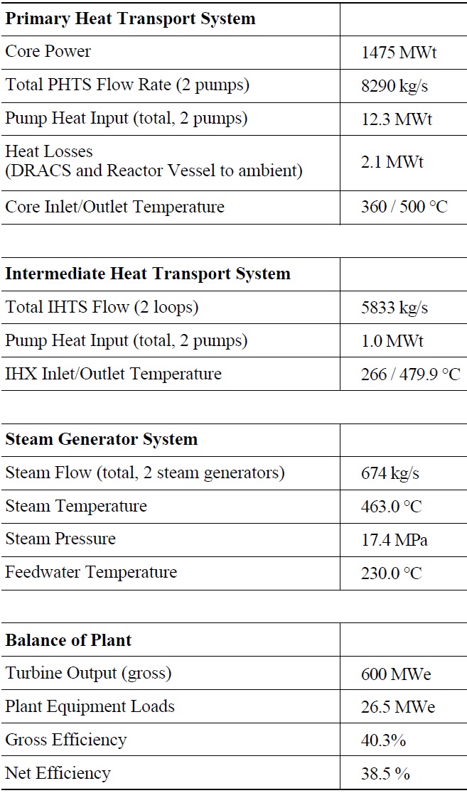
resulting superheated steam achievable with the use of liquid metal rather than water for the reactor coolant. The calculated net efficiency for the TWR-P reactor plant is 38.5% compared to approximately 30-35% for typical light water reactors. The TWR-P thermal-hydraulic design parameters and heat balance are summarized in Table 3.
[Table 3.] TWR-P Thermal-Hydraulic Design Conditions and Overall Heat Balance

TWR-P Thermal-Hydraulic Design Conditions and Overall Heat Balance
sodium coolant into the fuel assemblies through orifices that are varied based on the position in the core. The Reactor Enclosure System provides the majority of the primary system boundary, a portion of the containment system, the rotating plugs and their actuation, and the internal structural support for the core and core instrumentation. Primary features are the reactor and guard vessels, reactor head and rotating plugs, and the reactor internals (upper internal structure, thermal liners, and the redan structure). The reactor head also includes thermal and radiological shielding to maintain structural stability and allow personnel access, heating and cooling features, and a cable management system to interface the various cables and cooling lines with the movable rotating plugs.
The TWR-P reactor safety system follows both defense-in-depth
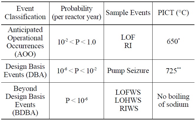
[Table 4.] TWR-P Acceptance Criteria*

TWR-P Acceptance Criteria*
and multiple redundancy methodologies. Two separate and independent control systems, a safety rod bank and a control rod bank, can be used to accomplish a cold shut down condition at any point in the life of the reactor. Decay heat removal is done via four independent safety grade DRACS loops. Inherent reactivity feedback allows the TWR-P reactor to be able to handle Anticipated Transients Without Scram (ATWS), without major damage to the fuel and/or cladding. The major categories of ATWS include Loss of Flow Without Scram (LOFWS), Loss of Heat sink Without Scram (LOHWS) and Reactivity Insertion Without Scram (RIWS).
The safety limits and acceptance criteria for the TWR-P reactor plant are expected to closely follow those of the current light water reactor and/or previous fast reactor designs. The preliminary acceptance criteria adopted in the conceptual design stage focus on preservation of fuel integrity and are listed in Table 4. Peak Inner Cladding Temperature refers to the maximum temperature reached during the transient.
Transient analyses were performed using SAS-4A/SASSYS1 safety code, version 3.1.228, developed at Argonne National Laboratory (ANL). This code system has been improved with new capabilities to model metallic fuel and benchmarked against the EBR-II reactor plant. Both protected transients and unprotected transients have been analyzed using SASSYS. In AOOs and DBAs, the reactor is assumed to SCRAM once the SCRAM signal occurs. The Reactor Shutdown System (RSS) is used in SASSYS to SCRAM the reactor automatically. However in ATWS, the RSS is assumed not to function. Only core reactivity feedback will control the reactor behavior.
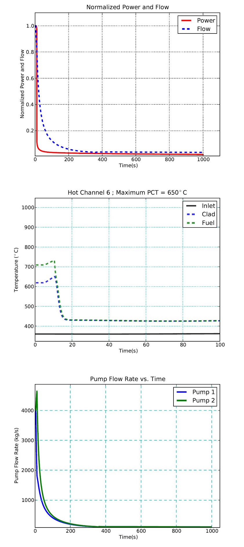
The loss of one primary pump is expected to represent one of the common DBAs in a two loop plant like TWRP. It starts with one primary pump tripped initially. The reactor will then scram due to low flow in this tripped
pump or high flux2/pressure trip with a 1 second delay. After the control rods have reached the core bottom, the other primary pump starts coasting down. The limit for this event is the PICT limit, which is established to ensure cladding integrity. Results for this transient are shown in Fig. 9. The clad temperature of the peak channel does not exceed the PICT limit of 650℃ and the pump coast down curves show expected behavior. At the beginning, pump 1 starts coasting down, reducing the pressure head in the core inlet plenum. Due to this lower pressure head, the flow rate in pump 2 increases. As pump number two starts coasting down due to the trip signal, this reduces the inlet plenum pressure further, which causes a slight change in slope of pump 1 flow rate.
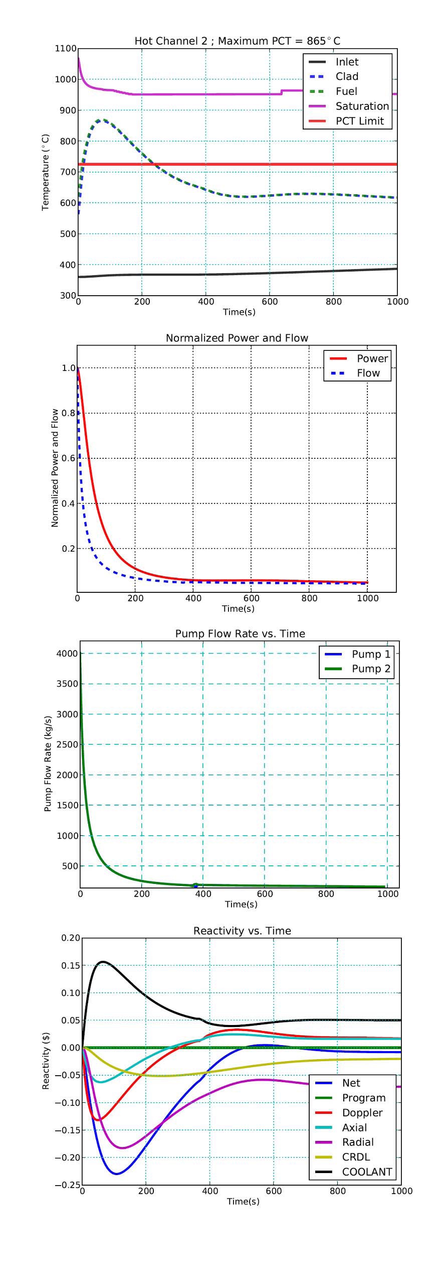
The response to an LOFWS accident will be shown for the category of beyond design basis accidents. It is assumed to be initiated by a total loss of offsite power. This causes the electrical power to be lost to all primary pumps, intermediate loop pumps, and feedwater pumps. In addition, there is a total failure to SCRAM the reactor so that the reactor power changes only due to the reactivity feedbacks introduced as a result of the flow and temperature changes in the core. The coast down of the primary pump is predicted by SAS4A/SASSYS-1 using the preliminary pump design data. The loss of the feedwater pumps causes the loss of heat rejection to the water-side at the steam generators.
Simulation results for the first 1000 seconds of the LOFWS transient are shown in Fig. 10. The curve labeled “Inlet” is the predicted coolant temperature at the subassembly inlet nozzles, below the lower shielde labeled “clad” is the predicted peak clad temperature in the active fuel region. At any point in time, the saturation temperature (“Sat.”) is the saturation temperature at the same location where the coolant temperature is plotted. Sodium boiling is not observed during the simulated transient, which satisfies the criteria in Table 4. The maximum cladding temperature is 865℃ and it occurs approximately 70 seconds into the transient. The duration of the cladding temperature above 725℃ is about 200 seconds. Exceeding the 725℃ limit will result in limited eutectic formation at the inner cladding layer, but even after one hour at 800℃, the observed penetration was minimal26. In the long term (not shown on Fig. 9), the peak cladding temperature peak reaches 530℃ at the time of 25 hours when the decay heat generation equals decay heat removal by two DRACS loops.
The only component of reactivity predicted to be positive is the coolant void, which peaks at approximately 0.16$ one minute into the transient. The programmed reactivity is zero since there is no control/safety rod reactivity insertion in this case. The dominant source of negative reactivity feedback is the core radial expansion feedback. The peak of radial expansion feedback is -0.18$.
In addition to LOFWS, RIWS and LOHWS accidents were also analyzed, showing even smaller PICT and peak fuel temperatures than LOFWS. Overall, safety analyses using SAS4A/SASSYS1 code showed that TWR-P has desirable safety characteristics. This includes no sodium boiling in ATWS due to inherent reactivity feedback. The fuel-clad integrity is preserved during protected transients, where redundant Reactor Shutdown Systems ensure a safe reactor shut down. In addition, sensitivity studies of
different reactor parameters (reactivity feedback, scram delay time, pump coast down time, etc.) on the transients will provide confidence in the analyzed results.
TWRs represent a near-term deployable and truly sustainable energy solution that is globally scalable for the indefinite future. They offer up to a ~30-fold gain in fuel utilization efficiency over existing light water reactors and represent the lowest cost alternative to enjoy the energy security benefits of an advanced nuclear fuel cycle without the associated proliferation concerns of chemical reprocessing. Furthermore, since TWR technology doesn’t require any reprocessing plants and eventually no enrichment plants, the risks from the two most proliferation prone parts of the fuel cycle are eliminated.
As demonstrated by the progress in this paper, Terra-Power is committed to maturing TWR technology in order to enable near-term deployment of TWR-P by the early 2020s and global commercial deployment shortly thereafter.