The design of a finite array requires an accurate determination of the mutual impedance between two elements and the mutual impedance matrix of whole array. An accurate approach using the moment method has been proposed for mutual impedance computation [1]. However, the moment method requires that each element be segmented into many basis functions; therefore, this method becomes tedious and time consuming as the number of elements in array increases. Several methods have been proposed that deal with the mutual impedance computation based on simplified models such as the transmission line model [2], and the magnetic current approximation [3]. These methods are much faster but may be inaccurate. Recently, a closed-form mutual impedance formula has been proposed, which is based on synthetic asymptote and variable separation [4-6]. In this formula, only 12 unknown coefficients are determined by matching with the simulated data or measured data. Therefore, this method is very fast and accurate due to its use of a synthetic asymptote form of the separated variables of the center-to-center spacing and the azimuth angle between two elements. However, when the center-to-center spacing is less than 0.5
In this paper, we propose a method to improve the closed- form formula for the mutual impedance computation between two very closely spaced elements. The mutual impedance formula is separated into two parts depending on the center-to-center spacing between two elements. When the spacing is more than 0.5
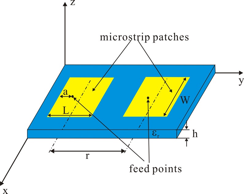
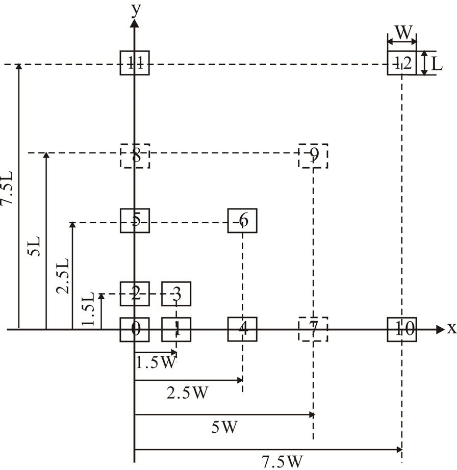
Fig. 1 shows the geometry of two coupled microstrip patch antennas. These antennas are designed to operate at 5 GHz on the dielectric substrate with
1. The Mutual Impedance Formula Based on the Synthetic Asymptote and Variable Separation
When the center-to-center spacing
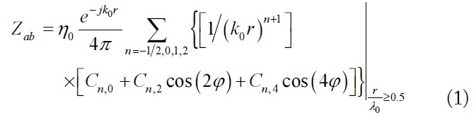
where
2. The Approximate Mutual Impedance Formula for Closely Spaced Elements
As mentioned above, when the spacing
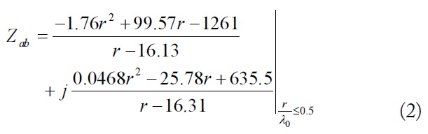
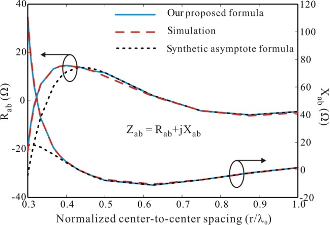
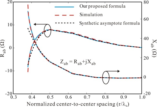
for E-plane coupling configuration, and
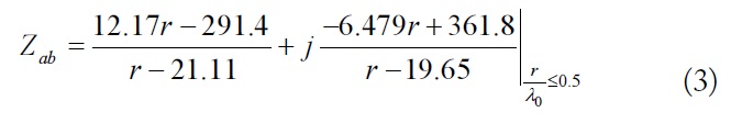
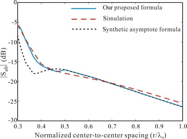
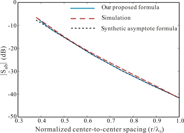
for H-plane coupling configuration. By combining Eq. (2) or Eq. (3) with Eq. (1), the mutual impedance between two elements in the E- and H-plane, respectively, can be accurately computed even through the center-to-center spacing
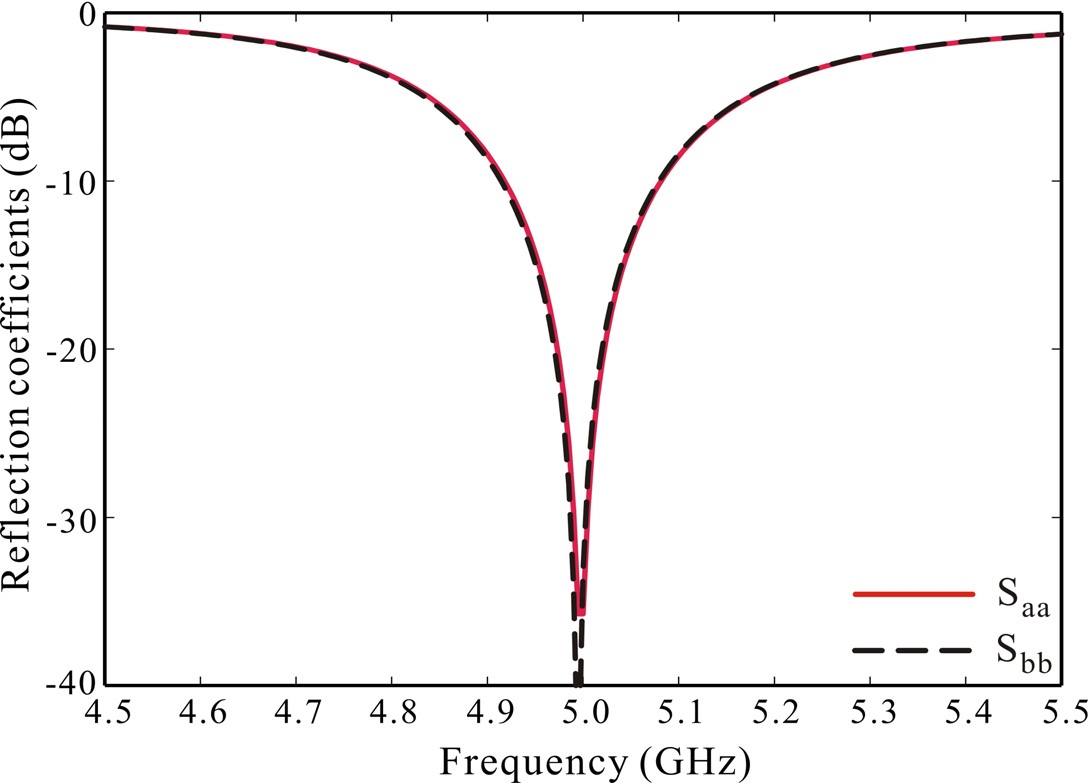
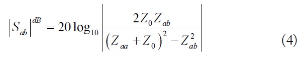
Fig. 3 plots the simulated reflection coefficients versus frequency of two microstrip patch antennas at the center-tocenter spacing of 0.5
First, the 12 unknown coefficients
[Table 1.] The 12 complex coefficients Cn,m
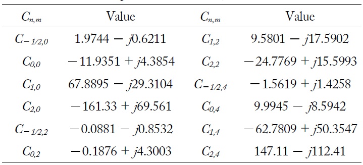
The 12 complex coefficients Cn,m
Once the 12 coefficients
Overlapping is avoided by choosing the minimum values of center-to-center spacing
The mutual coupling
where
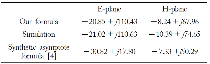
[Table 2.] Comparison of mutual impedance with the minimum spacing

Comparison of mutual impedance with the minimum spacing
An improvement in the closed-form formula for mutual impedance computation between two very closely spaced microstrip antennas in E- and H-plane has been presented. A good agreement was achieved between the simulation and computation. The computational results show that the proposed approach is feasible for application to the design of linear microstrip patch arrays with arbitrary element spacing.