A unified potentiostat circuit for both O2- and H2O2- based electrochemical glucose sensors was proposed and its function was verified by circuit simulations and measurement results of a fabricated chip. This circuit consisted of an operational amplifier, a comparator and current mirrors. The proposed circuit was fabricated with a 0.13 ㎛ thick oxide CMOS process and an active area of 360 ㎛ × 100 ㎛. The measurements revealed an input operation range from 0.5 V to 1.6 V in the H2O2- based bio-sensor and from 1.7 V to 2.6 V in the O2- based bio-sensor with a supply voltage of 3.3 V. The evaluation results showed that the proposed potentiostat circuit is suitable for measuring the electrochemical cell currents of both O2- and H2O2- based glucose sensors.
Recently, the aging of the population has progressed rapidly with economic growth and the development of medical technology. Accordingly, the number of patients with chronic diseases, such as diabetes and cardiovascular diseases, has increased. As diabetes has high death rate, there is a strong need for portable measurement instruments that can diagnose diabetes easily.
Electrochemical sensors, optical sensors, piezoelectric sensors and acoustic sensors are used to measure the blood glucose for the diagnosis of diabetes [1]. Among them, the electrochemical sensor is used widely, because it is simple to manufacture with compact size and fast diagnosis.
An electrochemical glucose biosensor is based on the enzyme, glucose oxidase (GOD). This enzyme catalyzes the oxidation of glucose, which is a two step reaction process.
Two different types of electrochemical glucose biosensors are available on the market: an amperometric sensor and potentiometric sensor. The amperometric glucose sensor is based on measurements of electron flow during the oxidation or reduction, but the potentiometric sensor measures the potential changes in local pH during the reaction process. The amperometric glucose sensor is used most commonly due to its simple structure and low cost.
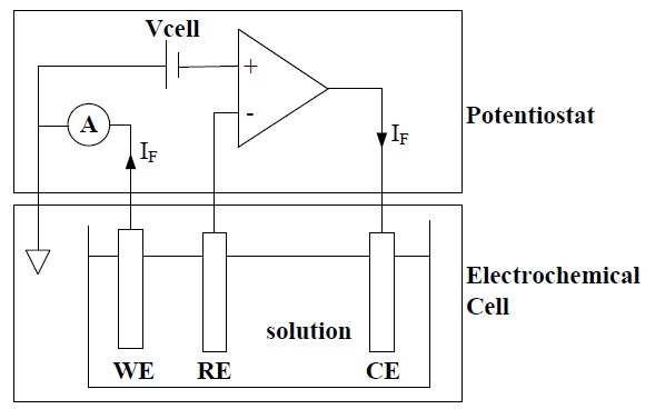
The amperometric electrochemical sensor consists of an electrochemical cell and a potentiostat, as shown in Fig. 1. The electrochemical cell consists of a working electrode (WE) onto which the reaction takes place, a reference electrode (RE) that maintains the constant potential, and a counter electrode (CE) that supplies the reaction current. The potentiostat supplies a desired cell potential Vcell between WE and RE, and measures the reaction current between the WE and CE [2].
Oxygen-electrode-based (O2-based) and hydrogen-peroxideelectrode- based (H2O2-based) sensors are the two most widely used electrochemical glucose biosensors. In an O2-based glucose sensor, when the cell potential Vcell between WE, made out of Pt, and RE, made out of Ag/AgCl, is typically -600 mV, WE emits electrons into solution by the reduction of oxidation at the surface of WE. Therefore, the output current is flowing from the CE to WE.
In the H2O2-based glucose sensor, when Vcell is typically +700 mV, WE absorbs electrons by the oxidation of hydrogen peroxide at the surface of WE. Therefore, the output current flows from the WE to CE [1].
Several configurations can be used to implement the potentiostat of an amperometric electrochemical sensor [3]. The method most commonly used is the use of a trans-impedance amplifier (TIA) that consists of two amplifiers. The first negative feedback amplifier is used to force Vcell to WE with reference to RE, and the second amplifier measures the current generated at WE. This circuit is simple and can measure low currents by increasing the feedback impedance. On the other hand, this technique requires the positive and negative input voltage to generate the current of both O2-based and H2O2-based sensor, because the direction of the current generated in the O2-based sensor is opposite to that of the current generated in the H2O2-based sensor
Other configurations to implement the potentiostat use a current conveyor [4-7]. This involves the insertion of a resistor in the current path at WE, where the voltage drop is measured. Another approach for the current measurement in the potentiostat is the use of a current mirror [3]. This technique is easy to design and requires few components. On the other hand, two types of potentiostats need to measure the current generated in the O2- based and H2O2-based sensors.
In this paper, a unified potentiostat circuit, which can measure the current of both O2-based and H2O2-based glucose sensors with one chip, was implemented using current mirrors. This potentiostat is very simple, has low power and a good measurement of current generated in both O2-based and H2O2-based glucose sensor.
This paper is composed of five sections. The potentiostat based on a current mirror is explained in section II and the circuit design of the proposed poentiostat is described in section III. The evaluation results of the fabricated chip are shown in section IV, and finally, the conclusions are reported in section V.
2. CURRENT MIRROR BASED POTENTIOSTAT
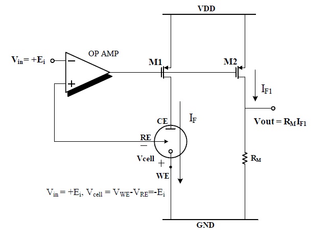
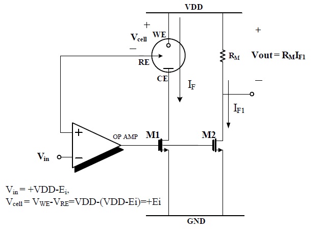
Figure 2 shows the current mirror-based potentiostat circuit for an O2-based glucose sensor.
The operational amplifier and MOSFET M1 were configured as a negative feedback loop through which the input voltage Vin = +600 mV was applied to the RE and WE is ground, then Vcell (VWE-VRE) is -600 mV. Under these conditions, reaction current IF flows from CE to WE and is copied to IF1 by the current mirror, which consists of M1 and M2. The voltage drop was measured across RM, which is proportional to the sensed current IF. This potentiostat circuit cannot be used for the H2O2-based sensor, because of the opposite polarities of the cell potential and currents.
Figure 3 shows the potentiostat circuit for the H2O2-based sensor.
In this circuit, Vin= VDD-700 mV was applied to the RE and WE is VDD respectively, then Vcell (VWE-VRE) is +700 mV and the reaction current flowed from the WE to CE and was measured by the current mirror, M1 and M2.
In current mirror typed potentiostat, two different potentiostats
are required to drive the O2- based and H2O2- based glucose sensor.
New potentiostat topology that can generate the cell potential of two different O2 and H2O2-based sensors using a current mirror
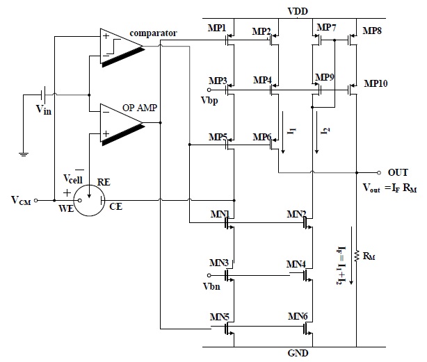
is described in this section. Figure 4 shows the proposed unified potentiostat that can manage opposite cell potentials and current flows in O2 and H2O2-based sensors.
The proposed potentiostat consists of a comparator, an operational amplifier and two cascode-type current mirrors. The voltage of WE (VCM) was set to half of the power supply voltage (VDD/2) to obtain the maximum input dynamic range. The comparator checks the polarity of the cell potential, Vcell=VWE-VRE= VCM-Vin, and deactivates the unnecessary current mirrors. The operational amplifier with MOSFETs MP1 and MN5 forms a negative feedback loop that keeps the potential of RE to Vin.
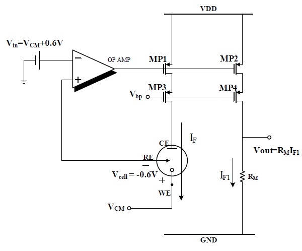
Figure 5 shows the equivalent circuit of potentiostat for the O2-based sensor. In an O2-based glucose sensor, Vin is set to VDD/2+600 mV to get a negative Vcell(-600 mV) and the comparator output is low, because Vin>VCM. Therefore, PMOS MP5 and MP6 are on and the PMOS current mirror MP1-MP4 is activated, but NMOS MN1 and MN2 are off and the NMOS current mirror MN3-MN6 and PMOS current mirror MP7-MP10 are deactivated.
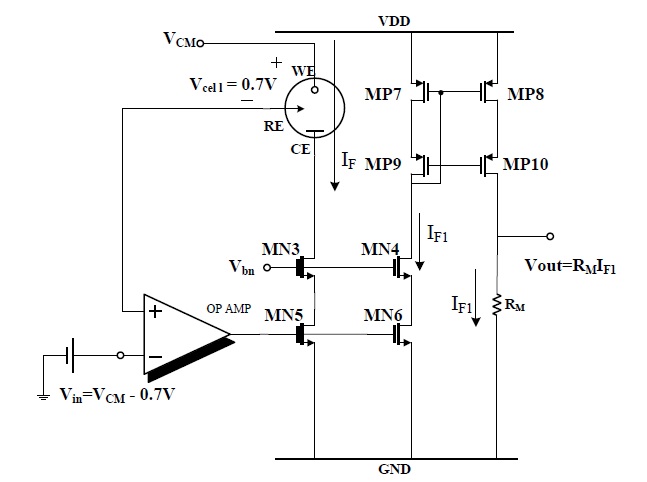
Figure 6 shows the equivalent circuit of the potentiostat for the H2O2-based sensor. In the H2O2-based sensor, Vin is set to VCM-Vcell = VDD/2-700 mV to have a positive cell potential (+700mV) and the comparator output is high, because Vin < VCM. Therefore,
PMOS MP5 and MP6 are off and the PMOS current mirror MP1-MP4 is deactivated, but NMOS MN1 and MN2 are on and the NMOS current mirror MN3-MN6 and PMOS current mirror MP7-MP10 are activated. The reaction current IF that flows from WE to CE is copied to RM by cascode current mirrors, MN3-MN6 and MP7-MP10. The sensed current is determined by the voltage drop through RM.
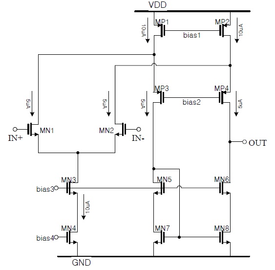
The operational amplifier was implemented by a folded cascode single stage amplifier that has only one pole to maximize the stability of the potential control loop, as shown in Fig. 7. The phase margin of this operational amplifier was approximately 82.8° and the open loop gain was 67.8 dB.
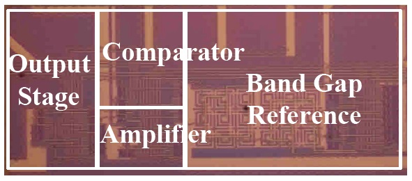
The proposed potentiostat circuit was verified by Cadence SPECTRE simulations using a 0.13 ㎛ thick oxide CMOS process. The layout was performed using Cadence Virtuso and verified using Mentor Calibre. Figure 8 shows the chip photography, which consists of a band gap reference, a comparator, an operational amplifier and an output stage. The area of the potentiostat
core was 360 ㎛ × 100 ㎛.
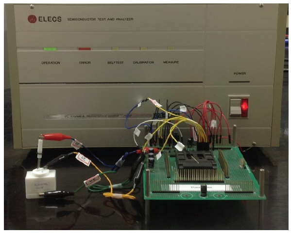
Figure 9 shows the photography of potentiostat measurement setup. This consists of the evaluation board, including a fabricated potentiostat chip, a parameter analyzer and an electrochemical cell of K3Fe (CN)6 solution.
First, we checked the performance of the fabricated chip with the electrical equivalent circuit of a three electrode electrochemical cell, instead of a K3Fe(CN)6 solution.
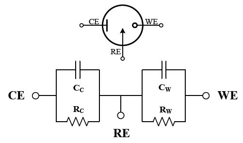
Figure 10 shows an electrical equivalent circuit of a three electrode electrochemical cell. In this model, the solution impedances are typically small and negligible. RC and RW represent the faradaic resistances, and CC and CW are the double layer capacitances associated with CE and WE, respectively.
These double layer capacitances and faradic resistances depend on the area of the electrodes and the solution concentration [8]. They can be expressed by
where CX is the capacitance of electrode X, AX is the area of the electrode X, and kC is a constant with an approximate value of 0.36 ㎌/㎟ [9]. RW is defined as
Note that RW must be recalculated based on the measured IF if Vcell is changed. Normally RW>>RC , because the area of the CE is larger than that of WE, and typical values in electrode to sense blood glucose are RW?1 ㏁, RC?10 Ω.
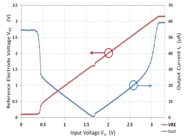
Figure 11 shows the measurement results of the fabricated chip with the equivalent circuit of the three electrode cell. The supply voltage VDD and common-mode voltage VCM were 3.3 V and 1.65 V, respectively. The RE voltage (left axis) followed the input voltage Vin from 0.5 V to 2.8 V, which confirms that the negative feedback loop by the operational amplifier and MOSFETs MP1 and MN5 is operating well. In addition, the measured currents (right axis) show that both potentiostats for the negative cell voltage like the O2-based sensor (Vin > VCM) and positive cell voltage like the H2O2-based sensor (Vin < VCM), worked well. The ranges of dynamic input voltage of this potentiostat are from 0.5 V to 1.6 V for the H2O2- based sensor and from 1.7 V to 2.6 V for the O2- based sensor.
Note that the faradaic resistance RW, which is a function of Vcell, was fixed in this measurement setup. Therefore, output current (IF) is proportional to the input voltage (Vin.) i.e.
We checked the operation of the proposed circuit with K3Fe(CN)6 solution, instead of the glucose solution, because the oxidation and reduction occur quickly in K3Fe(CN)6 solution. In contrast, in glucose, electrons are transferred very slowly and oxidation/reduction occurs slowly. Therefore, K3Fe(CN)6 solution is often used to check the operation of a potentiostat.
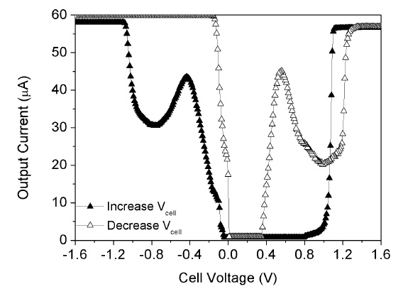
Figure 12 is the cyclic voltammetry measurement of 10 mM K3Fe(CN)6 solution using a fabricated potentiostat. The commercial electrodes, which consist of WE (Pt) and RE (Ag/AgCl),
[Table 1.] Measurement summary of the proposed potentiostat.
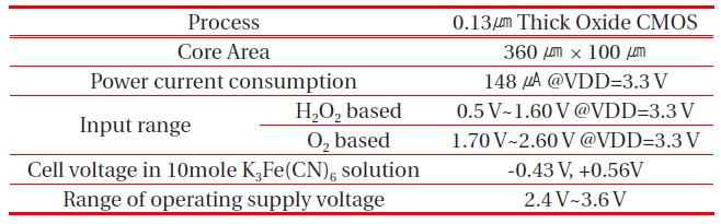
Measurement summary of the proposed potentiostat.
are used to sense the current reaction. When the cell voltage is increased from -1.6 V to +1.6 V, the maximum sensing current occurs at Vcell =-0.43 V. This means that this potentiostat drives the O2-based electrochemical glucose sensor. The maximum sensing current occurs at Vcell = +0.56 V when cell voltage decreases from +1.6 V to -1.6 V. This means that this potentiostat drives the H2O2-based electrochemical glucose sensor. These results show the proposed potentiostat can drive both O2 and H2O2-based electrochemical glucose sensors and detect the sensing current very well.
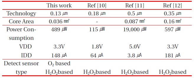
Table 1 summarizes the measurement results of the fabricated chip.
The performance of the proposed potentiostat is compared to that of other potentiostats in Table 2. The proposed potentiostat can drive both the O2 and H2O2-based electrochemical glucose sensors, but other potentiostats can drive only the H2O2-based electrochemical glucose sensors with positive power supply.
The core area of the proposed potentiostat is the smallest, even though this potentiostat can drive two kinds of electrochemical glucose sensors. The power consumption of the proposed potentiostat was lower than that of other potentiostats, except Ref [10], whose power consumption was a simulation result without chip fabrication. So, the power consumption of Ref [10] cannot be confirmed. From these comparative results, the proposed potentiostat is superior to conventional potentiostats.
This paper reported a new potentiostat circuit that can drive and measure the currents of both O2- and H2O2- based electrochemical glucose sensors with positive input voltage. In the proposed potentiostat, a one pole operational amplifier was used to obtain a stable feedback loop, which applies the cell potential, and cascode type current mirrors were used to achieve accurate copying of the reaction current. The proposed potentiostat was fabricated using a 0.13 ㎛ thick oxide CMOS process. The fabricated
[Table 2.] Performance comparison between the proposed potentiostat and other potentiostats.

Performance comparison between the proposed potentiostat and other potentiostats.
potentiostat was verified using the electrical-equivalent circuit of the electrochemical cell. Test results showed that the current of the O2-based sensor can be measured with the input voltage from 1.7 V to 2.6 V and that of the H2O2- based sensor could be measured with input voltage from 0.5 V to 1.6 V at a supply voltage of 3.3 V. The operation of the fabricated potentiostat was also confirmed using a K3Fe(CN)6 solution. These results show the proposed chip was a good potentiostat that can drive both O2-based and H2O2- based glucose sensors.