The transition from hard-wired to computer-based instrumentation and control (I&C) systems is connected to various challenges, e.g. the fundamental differences between hard-wired and computer-based technologies, the rapid evolution of computer-based technologies, human interaction issues and hybrid control rooms, qualification of new technologies and components, protection against common cause failures, cyber security, and so forth [1]. The focus of this paper is the technology based challenges affecting the I&C system design, for example, the allocation of I&C functions to I&C systems and components, implementation of the defense-in-depth concept [2], and management of complexity [3].
The I&C system design is of major importance to nuclear power plant engineering, because it is responsible for the transformation of the process related requirements into adequate I&C system architectures, and hence, the I&C system design directly contributes to the safety of nuclear power plants. Therefore, the I&C engineering efforts must be focused on extensive and thorough I&C system design activities, which are expressed in the modeling and analysis of I&C system designs.
Different publications emphasize the relevance of the I&C system design modeling and analysis in various contexts: [4] presents an approach for the modeling of computer-based I&C systems in the context of reliability analysis for the probabilistic risk analysis, [5] likewise models I&C systems for the reliability estimation, [6], in its “3+3 Process” approach, proposes the formal modeling of software, subsequent code generation, and coverage analysis, [7] evaluates description languages with respect to the modeling of CCF and dependencies, [8] considers the modeling of physical plant processes in order to improve the control system design, and [9] promotes the model driven engineering approach for small modular reactors.
The utilization of models in I&C engineering allows for a more efficient and qualitative engineering process [10], so that design decisions related to the I&C system design can be shifted to earlier life-cycle phases, i.e. modeling enables front-end loading. An important I&C engineering activity is the analysis of the I&C system models in order to verify and validate the I&C system dependability, as it is, for example, accomplished in [4] and [5]. Several I&C system analysis techniques are stated in [2], which include the defense-in-depth and diversity (D3) analysis, fault tree analysis (FTA), event tree analysis (ETA) and failure mode and effects analysis (FMEA). These analysis techniques must be adequately aligned with the modeling activities on one hand, but both I&C engineering activities, i.e. the modeling and analysis, must also be integrated in the lifecycle, on the other hand.
Although the detailed analysis techniques encompass different objectives, they all target proving the dependability, i.e. availability, reliability, safety, integrity, and maintainability [11], of the I&C system designs. On the contrary, the dependability of these system designs is threatened by failures of I&C systems and components, which can negatively affect required I&C functions, especially due to the aggregation of several I&C functions on single components. Therefore, I&C systems must be designed accordingly, so that failures do not prevent the control of event sequences challenging the nuclear power plants.
In the scope of this paper, a method for the modeling and analysis of I&C systems is proposed, which utilizes the framework provided by the IEC 61513 I&C safety lifecycle [12] and integrates partial concepts of the following analysis techniques: D3 analysis, FTA, ETA, and FMEA. This method is denoted as 2-step modeling approach and consists of two parts: the modeling of I&C systems and the analysis of these system models with respect to the superposition of failure combinations and event sequences, denoted as TeCoPS analysis. Based on the analysis results, the I&C system design can be accordingly modified early in the life-cycle. Moreover, this method contributes to I&C engineering simplification, due to the utilization of knowledge-based systems and the consequential partially automated analysis. The contribution within this paper builds on the common accomplishment of I&C projects utilizing the IEC 61513 life-cycle as a framework, and integrating well-known and accepted analysis techniques. However, the novelty of the presented concept targets the support of I&C engineering by introducing the principles for the utilization of computer-based tools for the I&C system design analysis. The modeling with the 2-step modeling approach represents a prerequisite for the generation of I&C system models; this, on one hand must take the modeling of temporal change of physical structure into consideration, and on the other hand must integrate the formal modeling for the computer supported analysis. On this basis, the introduced, partially automated TeCoPS analysis results in a simplified I&C system design analysis with less effort for I&C engineering, so that human failures throughout the analysis are prevented.
The paper is structured as follows. Section 2 shortly presents the metamodel for the modeling of I&C systems, followed by the discussion about the IEC 61513 I&C safety life-cycle in section 3, which is additionally adapted to the V-model. Section 4 introduces the method in which the initial utilization of the IEC 61513 I&C safety lifecycle for the modeling is presented, followed by the I&C system model analysis. The paper is concluded with a short summary.
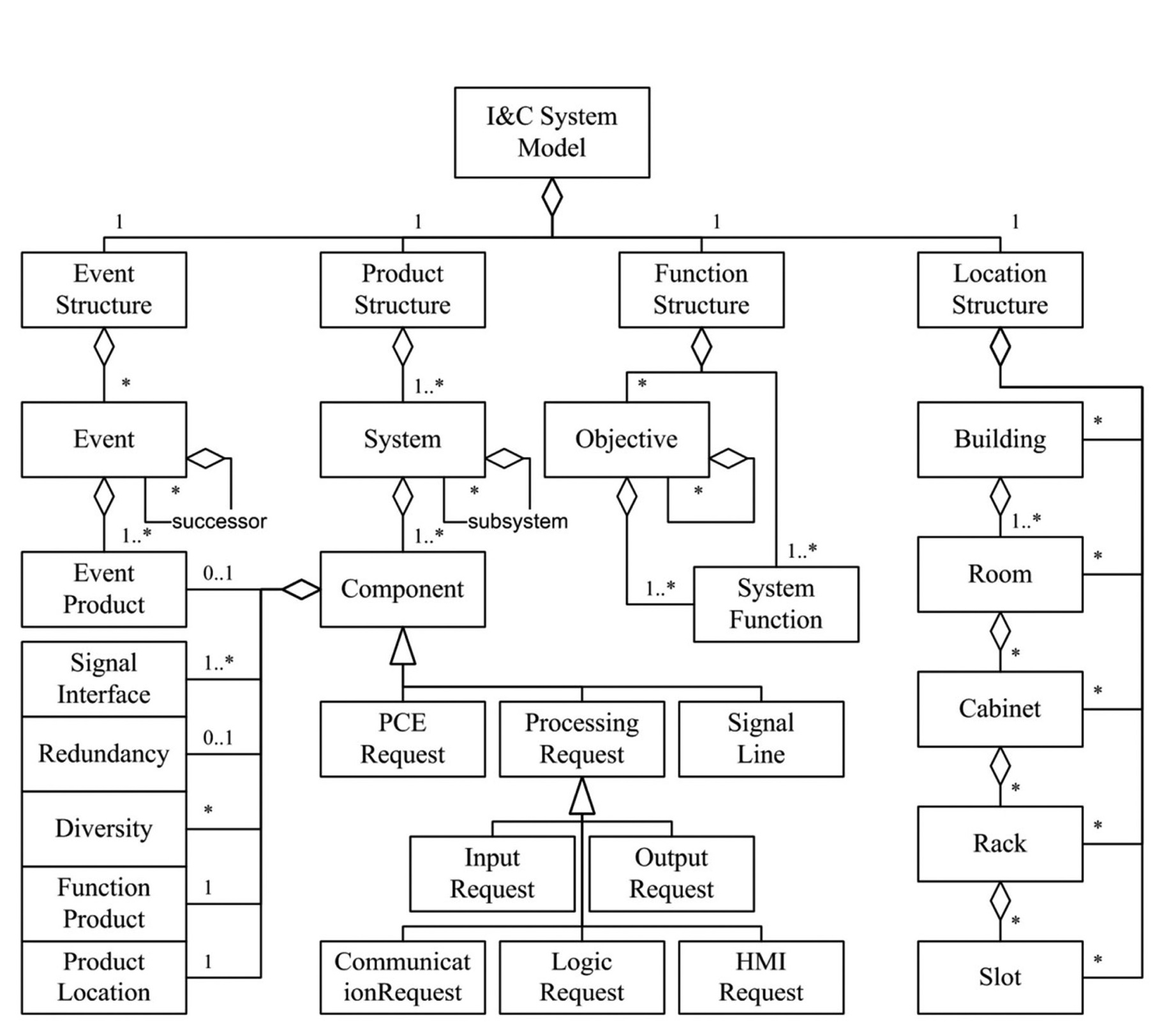
The basis for the modeling of I&C systems is constituted by the metamodel shown in Figure 1, which is discussed in more detail in the authors’ publications [13] and [14]. The metamodel is based on the description language AutomationML [15], which utilizes the description language Computer Aided Engineering eXchange (CAEX) [16]. For the presentation of the metamodel in Figure 1, a class diagram of the Unified Modeling Language [17] is utilized, where the presentation is limited to classes, and relationships modeling aggregations and specializations.
The structuring of the metamodel follows the standard IEC 81346 for the structuring of industrial systems [18], which yields the three structures to the right of Figure 1: the product structure1, function structure, and location structure. The location structure is comprised of the classes for the modeling of spatial information, the function structure consists of objectives and I&C system functions, and the product structure models systems, subsystems, and components. These three structures allow for the modeling of the required I&C system aspects, though as the structures are solely hierarchical and basically independent from each other, the modeling is completed by relationships, which
model the dependencies within and between the structures. Consequently, the metamodel enables the generation of comprehensive I&C system models.
2.2 Temporal Change of Physical Structure - TeCoPS
The product structure, function structure, and location structure allow for the modeling of static I&C system designs, but the changes due to failures are not considered. With respect to the stated objective of analyzing I&C system models, there is the necessity to integrate the modeling of failure combinations and event sequences in the metamodel, for which the event structure, shown to the left of Figure 1, is utilized.
Failures have their origin in the product structure, where the failure of a component results in the change of the product structure, though the effects must be analyzed within the function structure. The focus of the authors’ research is the temporal change of physical structure, i.e. the product structure, which only changes temporarily and has its cause in failures and maintenance. This is denoted as temporal change of physical structure, abbreviated as TeCoPS (see [14] for more details on TeCoPS).
The event structure allows for the modeling of parallel and independent event sequences, where successive events are hierarchically structured, and temporal dependencies are modeled with attributes. On one hand, the events are comprised of the capabilities for modeling failures, and on the other hand, events challenging the nuclear power plant and I&C systems can be modeled, so that these are superimposed in the event sequences.
2.3 Modeling TeCoPS Knowledge in a Knowledge- Based System
In order to adequately support I&C engineering, the analysis of the TeCoPS effects is automated under the utilization of the concept of knowledge-based systems (KBS) [19], which are generally applicable to the engineering of these systems [20]. This requires the formal modeling of TeCoPS [21], for which the Process Specification Language (PSL) [22] is utilized.
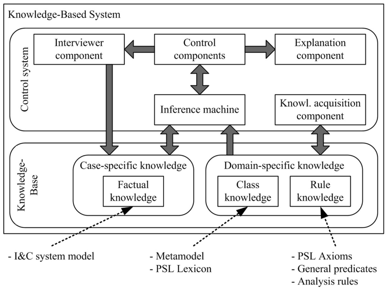
The general architecture of KBS is shown in Figure 2. KBS are composed of the control system and knowledgebase, where the control system serves as the user interface and controls the knowledge within the knowledge-base. The knowledge base consists of case-specific and domainspecific knowledge. The former represents the knowledge about a specific I&C system model, in this case generated utilizing the metamodel, whereas the latter represents the terminology of the domain under consideration, i.e. the class knowledge comprising the metamodel and PSL lexicon, and the rule knowledge, which is utilized for the inference of new knowledge. The rule knowledge is composed of the PSL axioms in order to control the consistency with PSL, general predicates modeling TeCoPS, and rules for the analysis of the effects of TeCoPS. More details about
the implementation of TeCoPS with PSL and KBS are presented in the authors’ publication [23].
1 The term product structure emanates from the standard IEC 81346 [18] and has the same meaning as physical structure or I&C system architecture.
The metamodel presented in the previous section is based on the context of I&C in nuclear power plants and provides comprehensive modeling capabilities for the generation of I&C system models. However, in order to thoroughly support I&C engineering, the metamodel must be combined with an adequate method for its application [24]. Moreover, the method must be aligned with the I&C life-cycle, so as to efficiently exploit the framework of the life-cycle for front-end loading.
The necessity for life-cycles in general, including lifecycles for I&C systems, is presented in paragraph 5.1 of [25], and their importance is emphasized in [2]. In the scope of international nuclear standards, these life-cycles are presented in [2] and [12], of which the latter standard, i.e. IEC 61513, provides more details on the life-cycle phases. For this reason, the IEC 61513 I&C safety lifecycle forms the basis of the 2-step modeling approach, i.e. the method addressed in this publication.
Before the method is presented in the fourth section, this section is concerned with the detailed presentation of the utilized IEC 61513 I&C safety life-cycle on the basis of [12] and the restructuring of the life-cycle in order to emphasize the verification and validation of I&C systems.
3.1 IEC 61513 I&C Safety Life-Cycle
The IEC 61513 I&C safety life-cycle [12] is two-part and is composed of the overall I&C safety life cycle and I&C system safety life-cycles. Each part consists of several, sequentially structured life-cycle phases, which are comprised of different activities and results. The overall I&C safety life-cycle considers all I&C systems on the plant
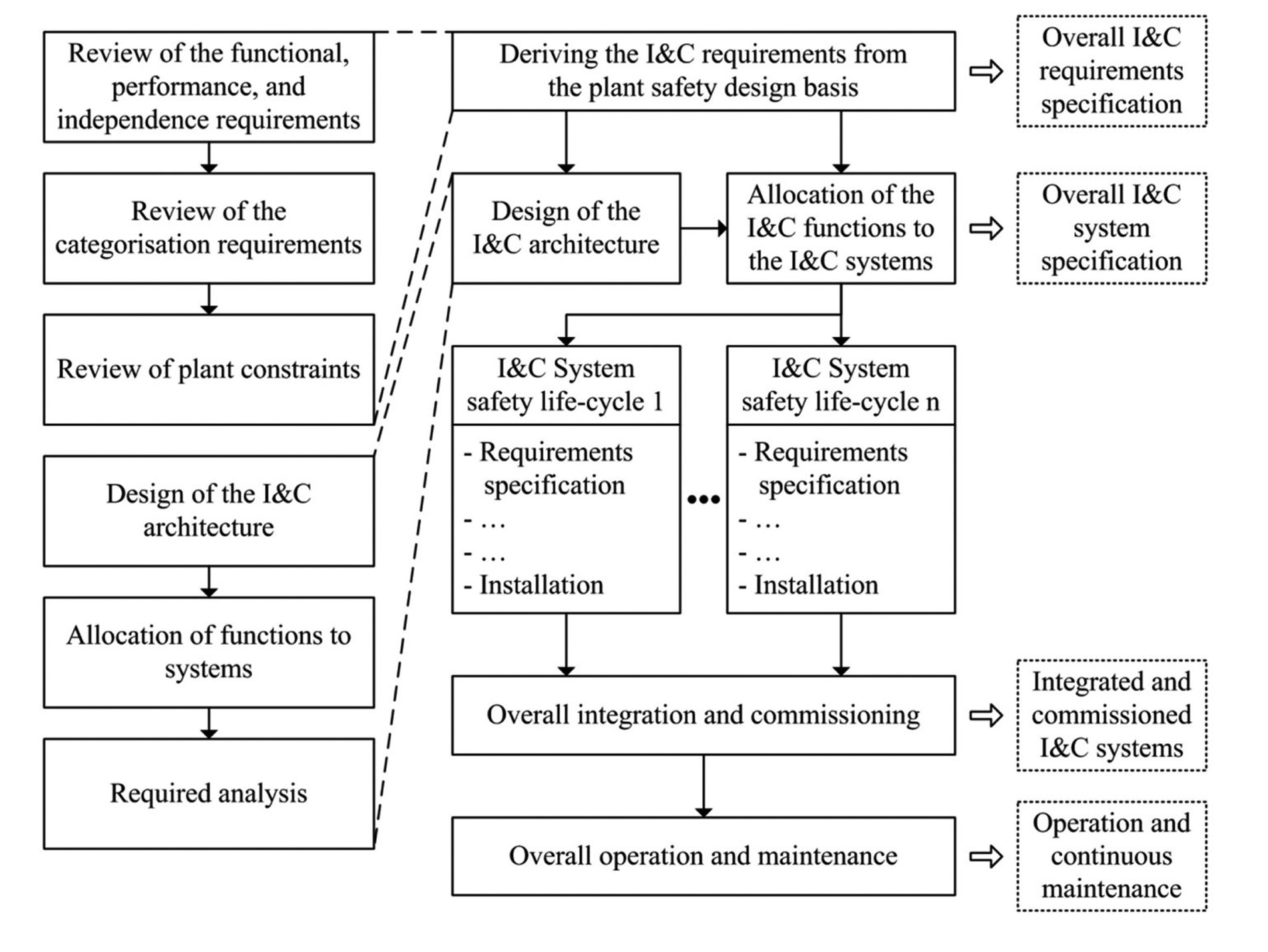
level, whereas the I&C system safety life-cycles solely concentrate on single I&C systems. Figure 3 shows the life-cycle phases and activities of the overall I&C safety life-cycle, supplemented by the relationship to the I&C system safety life-cycles.
The first phase of the overall I&C safety life-cycle is concerned with the derivation of I&C requirements from the plant safety design basis, resulting in the overall I&C requirements specification. This phase is divided into three activities, of which each activity considers different parts of the I&C requirements: functional, performance, and independence requirements, categorization requirements, and nuclear power plant requirements.
Based on the overall I&C requirements specification, the overall I&C system specification can be engineered, which represents the plant level I&C system design. Within this life-cycle phase, the activities of I&C architecture design, allocation of I&C functions to I&C systems, and required analysis are accomplished. With respect to the addressed challenges stated in the introductory section of this paper, this early life-cycle phase is of major importance to I&C engineering and requires thorough modeling and analysis of the I&C system design in order to realize the necessary front-end loading. Once this life-cycle phase is completed, any changes affect all further life-cycle activities. Thus, the activity of required analysis is of importance, for which [2] states the previously addressed analysis techniques.
The overall I&C system specification is followed by the I&C system safety life-cycles, where the I&C systems are designed, realized, and installed. The overall I&C safety life-cycle follows the I&C system safety life-cycles with the phase of overall integration and commissioning, which results in integrated and commissioned I&C systems. As
part of this life-cycle phase, the I&C systems are validated with respect to the plant level and system level requirements. The overall I&C safety life-cycle ends with the phase of operation and maintenance.
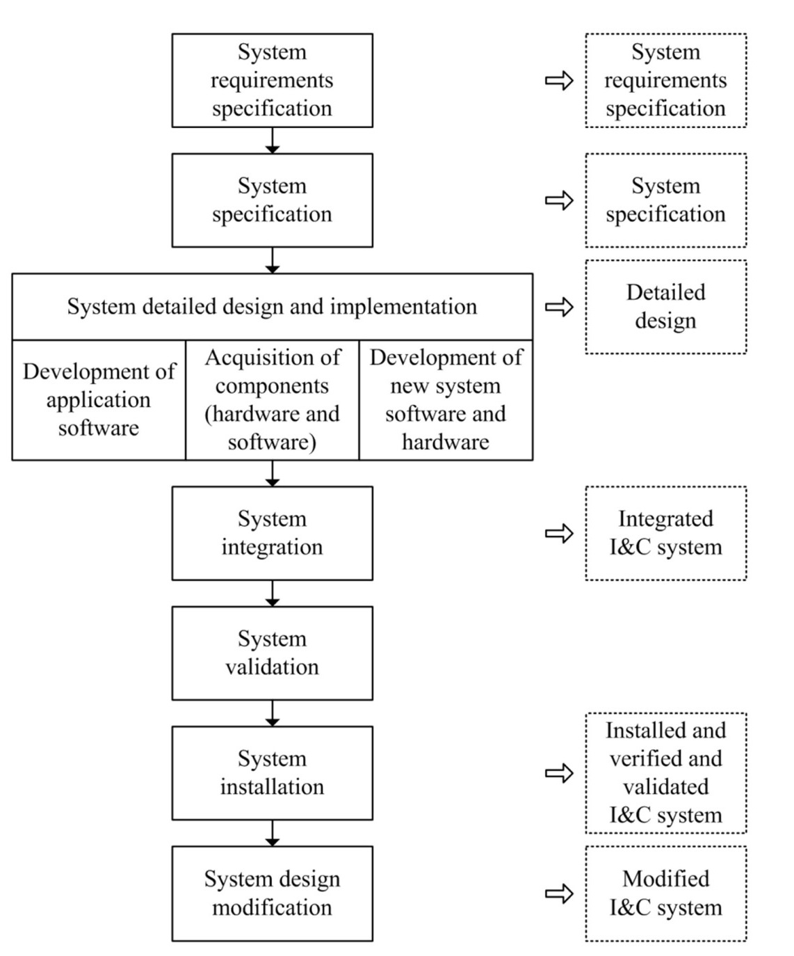
The overall I&C system specification serves as the input information for the I&C system safety life-cycle, which is shown in Figure 4 and starts with the life-cycle phase of system requirements specification. In this phase, the plant level requirements are broken down into system specific requirements related to the I&C functions, design constraints, I&C system boundaries, and environmental conditions.
These requirements are utilized for the I&C system design represented in the system specification, which provides information of the components, I&C system architecture, software requirements and allocation of I&C functions to components. This life-cycle phase corresponds to the overall I&C system specification phase and is of equal importance to I&C engineering. This means that the subsequent life-cycle phases, i.e. especially the I&C system realization, depend on the I&C system design output and I&C engineering must proceed thoroughly.
Based on the I&C system design, the realization of the I&C system can occur as part of the detailed design, which is separated into the realization of the hardware and software. The detailed design phase includes further required analyses related to the validation of the I&C functions and the reliability analysis. Subsequently, hardware and software are integrated as part of the system integration phase, validated as part of the factory acceptance test, and finally installed in the nuclear power plant, where the verification and validation of the installed I&C systems is accomplished. The design modifications represent the last life-cycle phase, but they are usually considered throughout the entire I&C life-cycle.
The structure of the IEC 61513 I&C safety life-cycle represents a top-down approach, where initially the I&C systems from the entire nuclear power plant are considered, followed by the design of separate I&C systems, and on the lowest level, hardware and software of the components are realized.
3.2 Structuring of Life-Cycles
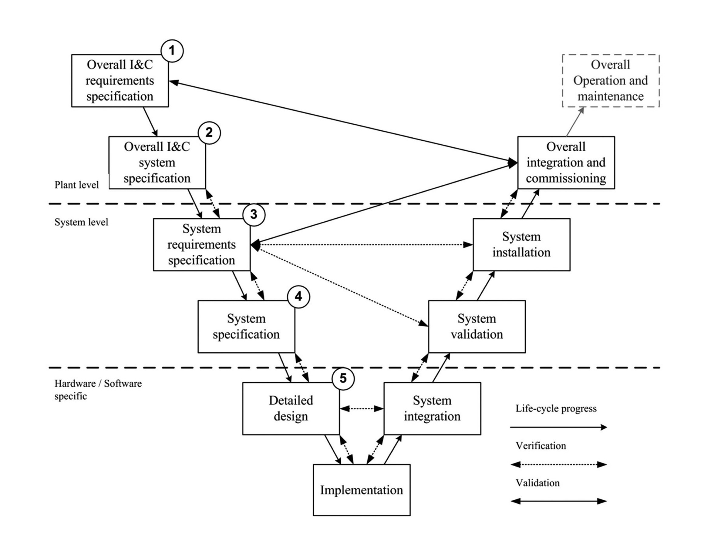
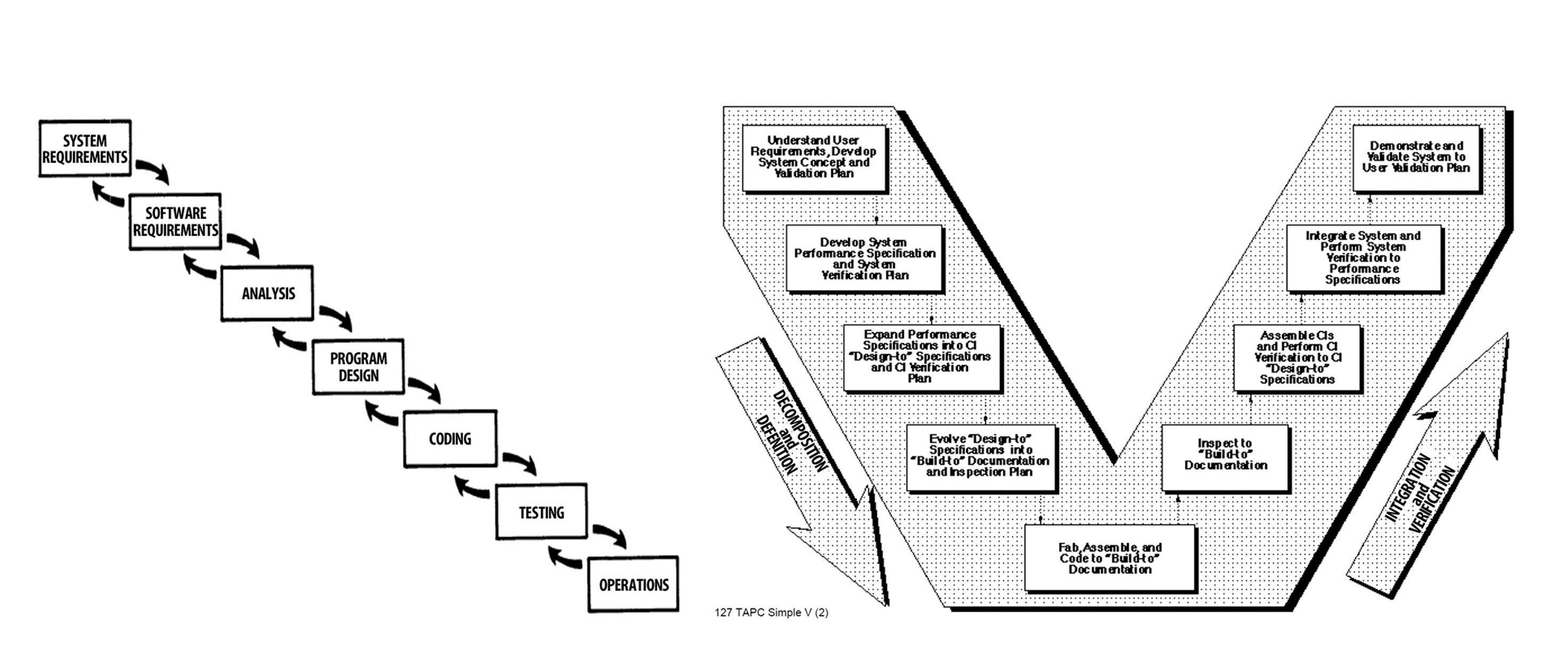
In general, life-cycles can be structured differently, so that their different aspects are emphasized [26]. Basic structuring approaches are, for example, represented by the waterfall model and the V-model, which are sketched in Figure 5.
The IEC 61513 I&C safety life-cycle, as it is presented in the previous section, is composed of sequentially structured life-cycle phases and implements the waterfall model, which was presented in 1970 in the scope of large software system developments [27]. Its shape resembles a waterfall, which illustrates the progressing development process. Furthermore, [27] identifies the necessity for iterations between the phases, points out the problem of required testing within the late life-cycle phases, and states five principles for minimizing the development risk, e.g. in the form of thorough documentation. However, the importance of the verification and validation (V&V) of I&C systems, so as to adequately prove their dependability, is not reflected in this structuring approach.
The importance of V&V for nuclear power plants was stated in the domain’s early years [28] and is also emphasized in the present standards, e.g. [2]. A general structuring approach of life-cycles considering the importance of V&V is constituted by the V-model [29], where the life-cycle phases are separated into two parts. The left part of the V-model represents the top-down design process starting with the requirements specification and ending with the realization, whereas the right part illustrates the bottomup integration and verification, i.e. its focus is on V&V. The distinctiveness of the V-model emanates from the relationships between its left and right parts. Each phase of the integration and verification part corresponds to phases of the design part, so that the V&V activities can distinctively revert to the design activities. Nowadays, the basic V-model structure is integrated into the lifecycle V-Model XT [30].
3.3 Restructuring of the IEC 61513 I&C Safety Life-Cycle
This section presents the authors’ proposal of restructuring the IEC 61513 I&C safety life-cycle according to the V-model, which is mainly motivated by the integration of the V&V concept in the life-cycle2. In addition, the restructuring supplements the alignment of the method with the life-cycle, so as to utilize the more closely connected life-cycle phases, and clearly implements an advantageous top-down decomposition of the I&C systems .
The restructured life-cycle is shown in Figure 63. The life-cycle phases correspond to the IEC 61513 I&C safety life-cycle as shown in Figure 3 and Figure 4, though the phases are denoted based on their results. Vertically, the restructured life-cycle illustrates the top-down decomposition of the I&C systems with respect to the plant level, system level, and hardware and software level. In other words, Figure 6 integrates the overall plant level and system level life-cycles. The left part of the restructured
life-cycle is composed of the I&C system design phases, whereas the phases to the right are concerned with the integration and verification. The relationships between the phases are presented by the arrows, where the life-cycle progress, verification, and validation are considered.
Verification is the quality assurance activity proving correct implementation, answering the question of whether the product is constructed correctly. On the contrary, validation is the quality assurance activity considering the correct objective of the implementation, as it proves whether the correct product is constructed [31]. In both cases, the reference is represented by the requirements.
Figure 6 illustrates the integration of V&V into the life-cycle. On one hand, subsequent life-cycle phases are connected by a required verification, resulting in the input information of a phase being based on correct information of the previous phase. On the other hand, V&V is performed between the life-cycle phases of the left and right parts of the V-model. The system integration must correspond to the detailed design, whereas in the phases of system validation and system installation the system requirements are verified. This verification solely concentrates on the fulfillment of requirements, such as the correct software implementation or installation of the I&C system components4.
The validation of the I&C systems is performed at the plant level under the consideration of all I&C systems, here the system level and plant level requirements are validated. This phase is of special importance, as the correct implementation of the I&C functions and I&C systems are proved, resulting in a sound basis for the operation.
The restructured life-cycle according to Figure 6 is utilized as the framework for the 2-Step modeling approach presented in the following sections, for which the generation of the I&C system models and subsequent I&C system design analysis is aligned with the early life-cycle phases.
2 This proposal is in line with the structuring of the life-cycle presented in [2] according to the V-model.
3 The numbering of the first life-cycle phases serves the relationship between the life-cycle and method, which is utilised in section 4.
4 For this reason, the life-cycle phase of system validation solely verifies the system requirements.
4. METHOD FOR THE MODELING AND THE ANALYSIS OF I&C SYSTEM DESIGNS
On the basis of the metamodel presented in section 2 and I&C life-cycle discussed in the previous section, this section presents the method for the modeling and analysis of I&C system designs. In general, the method is two-part, where the first part is concerned with the modeling of the I&C systems, i.e. the 2-step modeling approach, and the second part considers the analysis of temporal change of physical structure, i.e. the TeCoPS analysis.
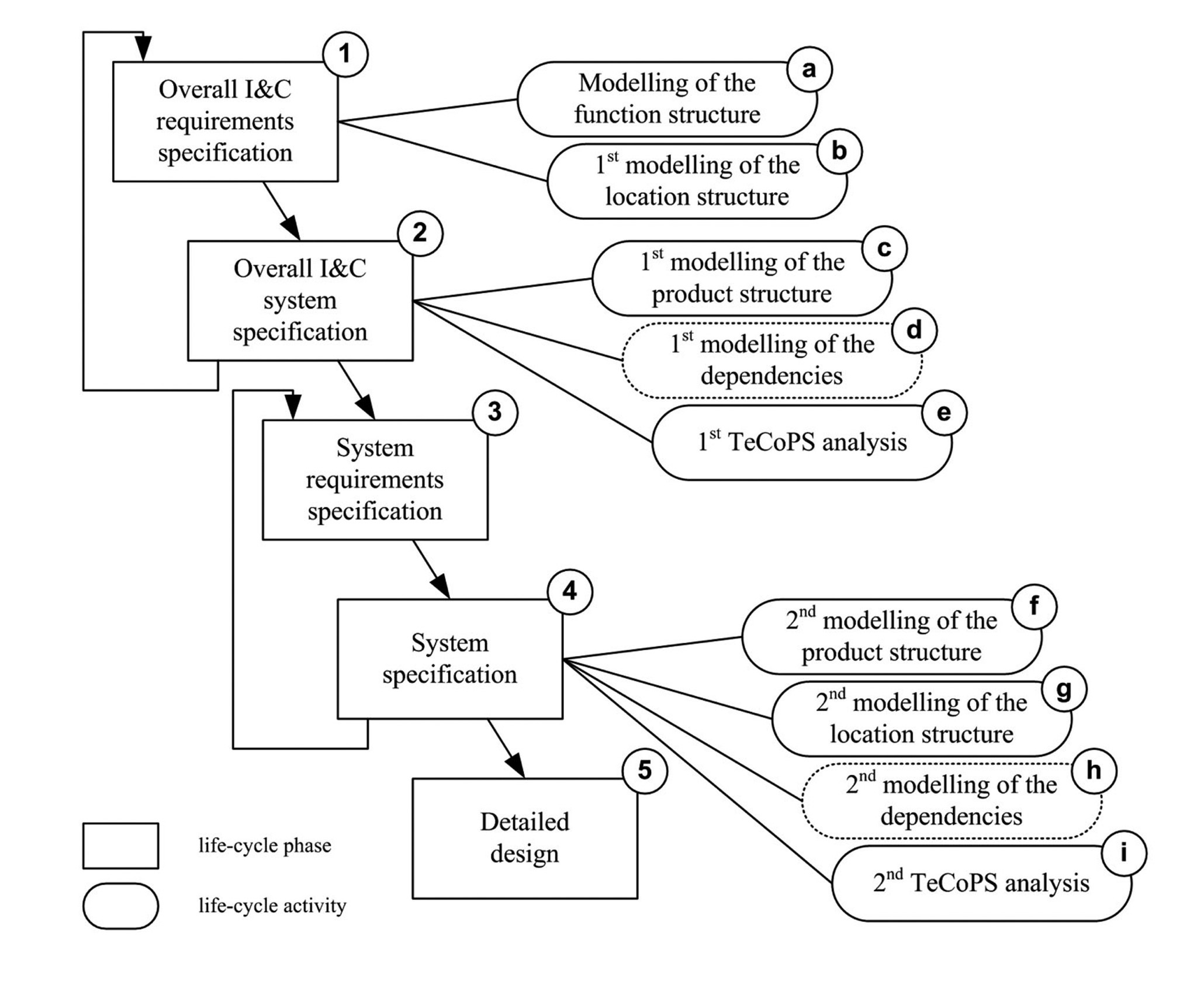
The objective of the method for the analysis of I&C system designs is realizing front-end loading, so that the I&C systems can be modeled and analyzed as early in the life-cycle as possible. Consequently, the modeling and analysis is based on two steps. In a first step, the I&C systems are modeled and analyzed on the plant level, followed by the refinement of the modeling and analysis on the system level. The overview of the 2-step modeling approach is shown in Figure 7.
To the left of Figure 7, the relevant life-cycle phases are shown, whereas to the right the life-cycle activities are presented. The life-cycle phases in Figure 7 are the same as in IEC 61513 I&C safety life-cycle according to Figure 6, which is highlighted by the numbering5. The modeling of the I&C systems in the first step is based on information of the overall I&C requirements specification phase (1) and the overall I&C system specification phase (2). The function structure (a), can be modeled in the course of the first life-cycle phase (1), because the I&C functions originate from process engineering and this information is the input to the entire I&C system design. Likewise, the location structure (b) can superficially be modeled, as at least the required buildings and rooms are known. The product structure (c) is modeled in the second life-cycle phase (2), based on the I&C system design information, i.e. the I&C system architecture. After the three structures are modeled, the dependencies (d) between the structures can be modeled, at which the allocation of the I&C functions to I&C systems is of major importance. Subsequently, the I&C system designs on the plant level can be analyzed with respect to the superposition of failure combinations and event sequences (e), for which the TeCoPS analysis specified in section 4.3 is utilized. In dependence of the TeCoPS analysis results, the I&C system design could require modifications, resulting in I&C engineering going back to the overall I&C requirements specification phase (1). This iteration is repeated until the analysis results are satisfactory, and subsequent I&C engineering activities can build on a solid basis.
On the system level, plant level requirements are broken down into the system requirements specification (3) as usual, and the I&C system specification (4) is accomplished. As part of this life-cycle phase, the entire modeling capabilities are utilized for the generation of the completed I&C system models. This includes the life-cycle activities (f) and (g), as well as the modeling of all dependencies (h) between the structures. In consequence, the system specification phase (4) is finished with the second TeCoPS analysis (i). According to [12], this phase does not comprise of any analyses, though the TeCoPS analysis is introduced in order to achieve a solid basis for the detailed design phase (5) and subsequent I&C system implementation. Likewise, based on the analysis results, I&C engineering must go back to the system requirements specification phase (3), so as to modify the system level designs.
The separation of the modeling and analysis approach into two parts allows for front-end loading, so that initially the plant level design can be accomplished and, if required, modified. This results in sounder I&C system designs and avoids design changes in late life-cycle phases. The refinement of the modeling and analysis in a second step repeats the entire method, though with more detailed design information. In consequence, the detailed design can revert to sound I&C engineering, which also affects the V&V life-cycle phases, because correct, results are to be expected.
4.2 Existing Analysis Techniques
For the analysis of the I&C system models with respect to the superposition of failure combinations and event sequences, existing analysis techniques are integrated in the TeCoPS analysis. This section briefly presents the utilized analysis techniques.
4.2.1. D3 Analysis
The diversity and defense-in-depth (D3) analysis is presented in [32]. Its objective is the analysis of computerbased I&C systems with respect to common cause failures. The background and motivation for the D3 analysis is the inherent susceptibility of computer-based I&C systems to common-cause failures. The I&C system design utilizes various design features, e.g. redundancy, independence, and separation, though the design feature of diversity is seen as most effective against common cause failures. The design feature of diversity is separated into six attributes: design diversity, equipment diversity, functional diversity, signal diversity, and software diversity, which are seized and elaborated in [33] for the implementation of diversity strategies.
For the D3 analysis the I&C systems are initially modeled based on blocks, which represent black boxes on the lowest level of I&C system aspects under consideration. The blocks are differentiated by the diversity attributes, and failure of the blocks affects all block output signals equally.
In the course of the D3 analysis, concurrent failures of the same blocks, i.e. blocks utilizing the same hardware and software, are postulated, blocks’ output signals are assumed to fail, and effects of postulated common cause failures must be manually analyzed by I&C engineering. The boundary conditions for the analysis are represented by the plant design basis event sequences challenging the nuclear power plant and I&C systems.
The D3 analysis is strongly dependent on I&C engineering know-how, as the engineers must determine the scope of common cause failures to be postulated and rely on comprehensive information for analysis of the effects.
4.2.2. ETA and FTA
The event tree analysis (ETA) and fault tree analysis (FTA) are usually applied in combination as part of the probabilistic safety assessment [34] in order to determine the core damage frequency.
The objective of the ETA [35] is to represent any kind of event sequence, and is mostly utilized for the analysis of abnormal conditions and accidents of technical systems. The starting point for the ETA is the initial event, e.g. a component failure, for which the sequential events are developed until final events are reached, which either represents a safe or a hazardous state. For each level in the ETA, the system response in the form of functions is considered, i.e. the functions either fail or operate, resulting in the characteristic tree shape. The ETA is completed by probabilistic values for the events, so that these values for the final events can be determined.
On the contrary, the FTA’s objective is to determine the causes of an undesired event [36]. The starting point for the top-down FTA are the events of the ETA, for which engineering has to determine the causes based on a comprehensive knowledge about the underlying technical system. The causes are hierarchically decomposed and combined, yielding different cut sets, i.e. minimal sets of causes, responsible for the undesired event. The FTA can likewise be completed with probabilistic calculations in order to determine systems reliability.
4.2.3. FMEA
The failure mode and effects analysis (FMEA) [37] is a bottom-up approach for the analysis of system failure effects. As part of the FMEA, engineering postulates different single failures, and the effects on the operation, functions, and system states are analyzed. The bottom-up approach is expressed in a hierarchical decomposition of the technical system, for which the failures are postulated on the lowest hierarchy level, and effects are analyzed on the following levels. Typically the FMEA is accomplished for single failures, but, for example, [38] and [39] also consider the FMEA for multiple failures.
The 2-step modeling approach concentrates on the modeling of I&C systems along the life-cycle, whereas the TeCoPS analysis represents the life-cycle activities (e) and (i), which are shown in Figure 7. The TeCoPS analysis integrates partial concepts of the presented D3 analysis, FTA, ETA, and FMEA, and results in a combination of bottom-up and top-down analysis approaches. Out of the existing analysis techniques, the D3 analysis is the most decisive with its superposition of postulated common cause failures and event sequences. This approach is extended to the postulation of single and multiple failures, so as to encompass the FMEA and ETA/FTA approaches and model any kind of failure combination. Moreover, the bottom-up and the top-down approaches of the FMEA and FTA are combined in order to allow for flexibility in the analysis, and guarantee for completeness.
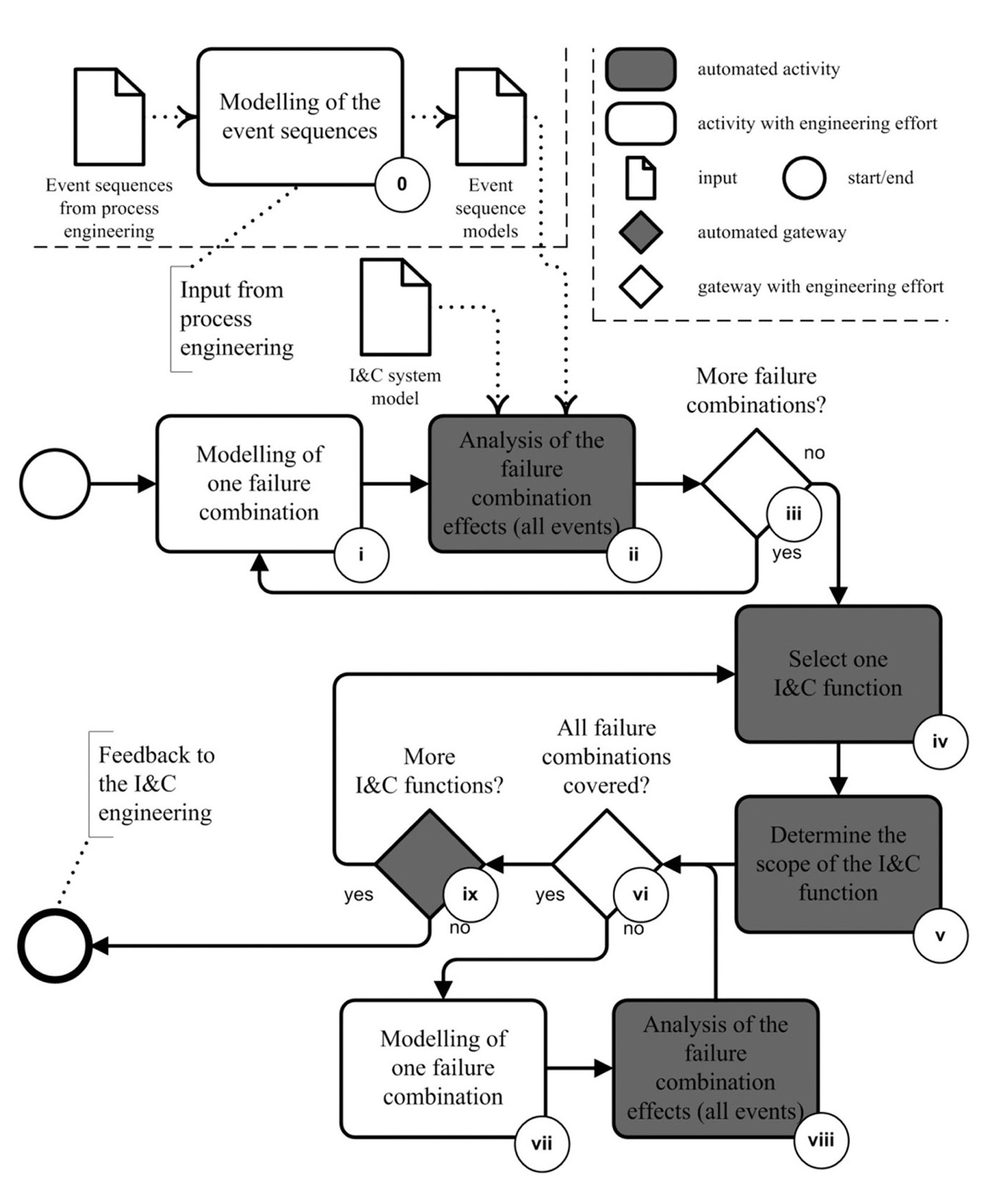
Figure 8 shows the overview of the TeCoPS analysis, of which the highlighted activities are automated and the remaining activities require I&C engineering effort. Input information to the analysis of the effects of failure combinations, as shown in the upper part of Figure 8, is the I&C system model according to the metamodel and the event sequence models. The former input information represents the output of the 2-step modeling activities (a) to (d) and (f) to (h), which depend on the considered step of the 2-step modeling approach, whereas the latter input information originates from process engineering and is modeled utilizing the event structure of the metamodel (see section 2.2), as shown in Figure 8 within the activity (0), and is out of scope of the TeCoPS analysis.
The TeCoPS analysis starts with the bottom-up modeling of different failure combinations as part of activity (i), which are of concern to I&C engineering. For each failure combination the effects are automatically analyzed for all modeled event sequences within activity (ii). Based on the implemented rules in the knowledge base of the KBS, the analysis yields the information on either the successful control of the event sequences, or points out the deficiencies in the design. The activity of the automated analysis is followed by the decision of engineering to model further failure combinations (iii), which would result in an iteration of the activities (i) to (iii).
Once engineering is finished with the modeling of its desired failure combinations, the TeCoPS analysis is completed with a top-down approach, where the modeling of the failure combinations is checked for completeness. The TeCoPS analysis automatically selects one I&C function (iv), determines all involved components in the I&C function (v), and yields the possible failure combinations, i.e. single, multiple, and common cause failures. Engineering then decides on whether the proposed failure combinations make sense as part of activity (vi), so that these can be analyzed6. This analysis is also comprised of the iteration of failure combination modeling (vii) and automated analysis (viii). A further iteration is accomplished based on the I&C functions in activity (ix), so that the check for completeness covers all I&C functions, components, and failure combinations.
When all failure combinations are analyzed, the TeCoPS analysis is finished and the analysis results represent the feedback to I&C engineering. As addressed before, the feedback is composed of the failure combinations, unsuccessful control of the corresponding event sequences, and deficiencies in the design, e.g. missing redundancy, diversity, or separation.
The TeCoPS analysis solely concentrates on the I&C system design consisting of the I&C functions, I&C system architecture, and spatial layout. In contrast to the FMEA or FTA, the I&C system behavior is not considered, because this information is not available before the detailed design, and contradicts the need for front-end loading.
5 Throughout the description of the method the reference to the numbering is stated in brackets.
6 When there are defined rules for the failure combinations to be postulated, e.g. only single or double failures, then the entire check for completeness can be automated.
This paper addresses the challenge of I&C system design, and especially the analysis of the effects with respect to the superposition of failure combinations and event sequences on the I&C system design, for which a method for the analysis of temporal change of physical structure within the I&C life-cycle is presented.
Preceding the method presentation is a discussion about the I&C life-cycle. The IEC 61513 I&C safety lifecycle is introduced and its structure is adapted to the Vmodel, so that the importance of V&V is adequately considered.
The method for the analysis is two-part and consists of the 2-step modeling approach and TeCoPS analysis. In combination, both parts realize the required front-end loading, so that the design decisions can be verified by I&C engineering early in the life-cycle. The TeCoPS analysis simplifies I&C engineering by utilizing the concept of KBS, which allows for the semi-automated analysis. This reduces the I&C engineering effort throughout the I&C system design analysis, which specifically is advantageous under consideration of the I&C system complexity. As a prerequisite, the metamodel provides the required formal I&C system models, including TeCoPS. However, the analysis results are dependent on the analysis rules as part of the rule knowledge, which must be comprehensively engineered.
Examples for the modeling of I&C systems utilizing the metamodel are presented in the stated references of the authors, supplemented by the exemplary application of the overall concept, i.e. the combination of the metamodel and the method, as part of real projects accomplished in the plants of the first author’s employer. The positive results of these applications confirm the applicability of the overall concept.


![Overall I&C Safety Life-cycle [12]](http://oak.go.kr/repository/journal/12708/OJRHBJ_2013_v45n5_653_f003.jpg)
![I&C System Safety Life-cycle [12]](http://oak.go.kr/repository/journal/12708/OJRHBJ_2013_v45n5_653_f004.jpg)
![Basic Life-cycle Structures: the Waterfall Model [27] and V-model [29]](http://oak.go.kr/repository/journal/12708/OJRHBJ_2013_v45n5_653_f005.jpg)