Removal of the decay heat for a prolonged period is a significant reactor safety concern, especially after an accident like SBO. Failure to remove decay heat may cause the fuel temperature to rise to unacceptable levels and can cause core melt accidents like Three Mile Island and Fukushima. In such a scenario, passive systems play important roles. The new generation reactors are being designed with this aspect in mind [1-5].
Advanced Heavy Water Reactor (AHWR) [5] is an innovative reactor designed for thorium utilization with special emphasis on the use of passive systems for normal operation and accidents. It is a vertical-pressure-tube-type heavy-water-moderated and boiling-light-water-cooled reactor. AHWR employs natural circulation as the mode for removing the fission heat from the reactor core during normal operation as well as during accidental conditions. Besides, AHWR design incorporates various passive safety systems which include an Isolation Condenser System (ICS) for removal of decay heat, a Passive Containment Cooling System (PCCS) for containment cooling and depressurization, passive ECCS injection directly into the channels in case of a LOCA, a Passive Poison Injection System (PPIS) to shut down the reactor passively in case of nonavailability of the wired shut down system, passive submergence of the core and feeders in a subcooled water pool in case of a LOCA using the water from GDWP, and a Passive Containment Isolation System (PCIS) for isolating the containment from the external atmosphere during a LOCA. The Passive systems in the AHWR are based on simpler designs operating without an external source of energy. This enables them to avoid human intervention in their operation and hence enhances their reliability.
The recent Fukushima accident has raised strong concern and apprehensions about the safety of reactors in case of a prolonged SBO continuing for several days. In view of this, a detailed study has been performed simulating such a low probable condition in AHWR. A scenario similar to Fukushima was postulated for the AHWR and analyses were performed to evaluate the capability of the reactor to manage the decay heat by passive means for several days, assuming operators have walked away. The analyses were performed using the code RELAP5/MOD3.2. The results indicate that the reactor, after being shut down safely on a seismic signal similar to that in Fukushima, can remove the decay heat by passive means using ICs which dissipate the heat into the GDWP. The large pool of water in the GDWP (~ 8000 m3) can absorb the decay heat for more than 50 days. The steam generated by boil-off of the water in the GDWP can condense passively on the walls of containment and on the tubes of the PCCS without exceeding the containment design pressure even for 16 days. If venting is carried out beyond this period, the decay heat can be removed passively for more than 50 days.
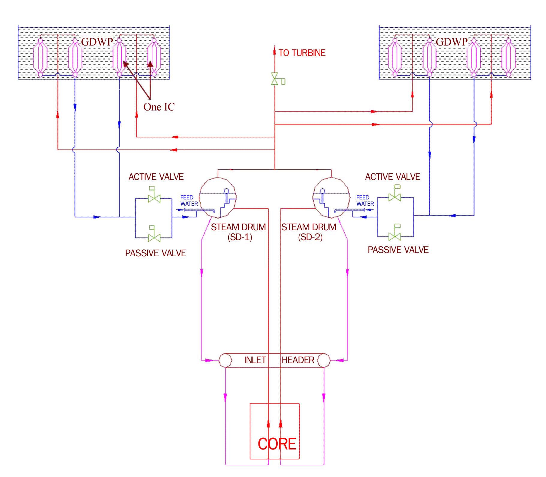
The most important concept adopted in this reactor is natural circulation as the desired heat removal mode from the core under all conditions of operation. Decay heat removal is also accomplished in a passive manner by establishing a natural circulation path between the Main Heat Transport System (MHTS) and the Isolation Condenser System in case of a SBO as mentioned earlier. Table-1 shows the important design parameters of AHWR. Figure 1a
[Table 1.] Important Design Parameters of AHWR
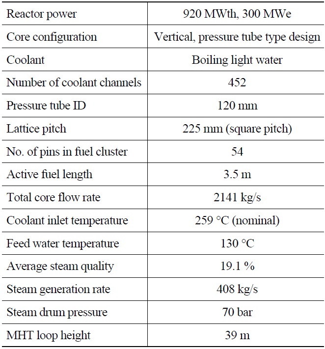
Important Design Parameters of AHWR
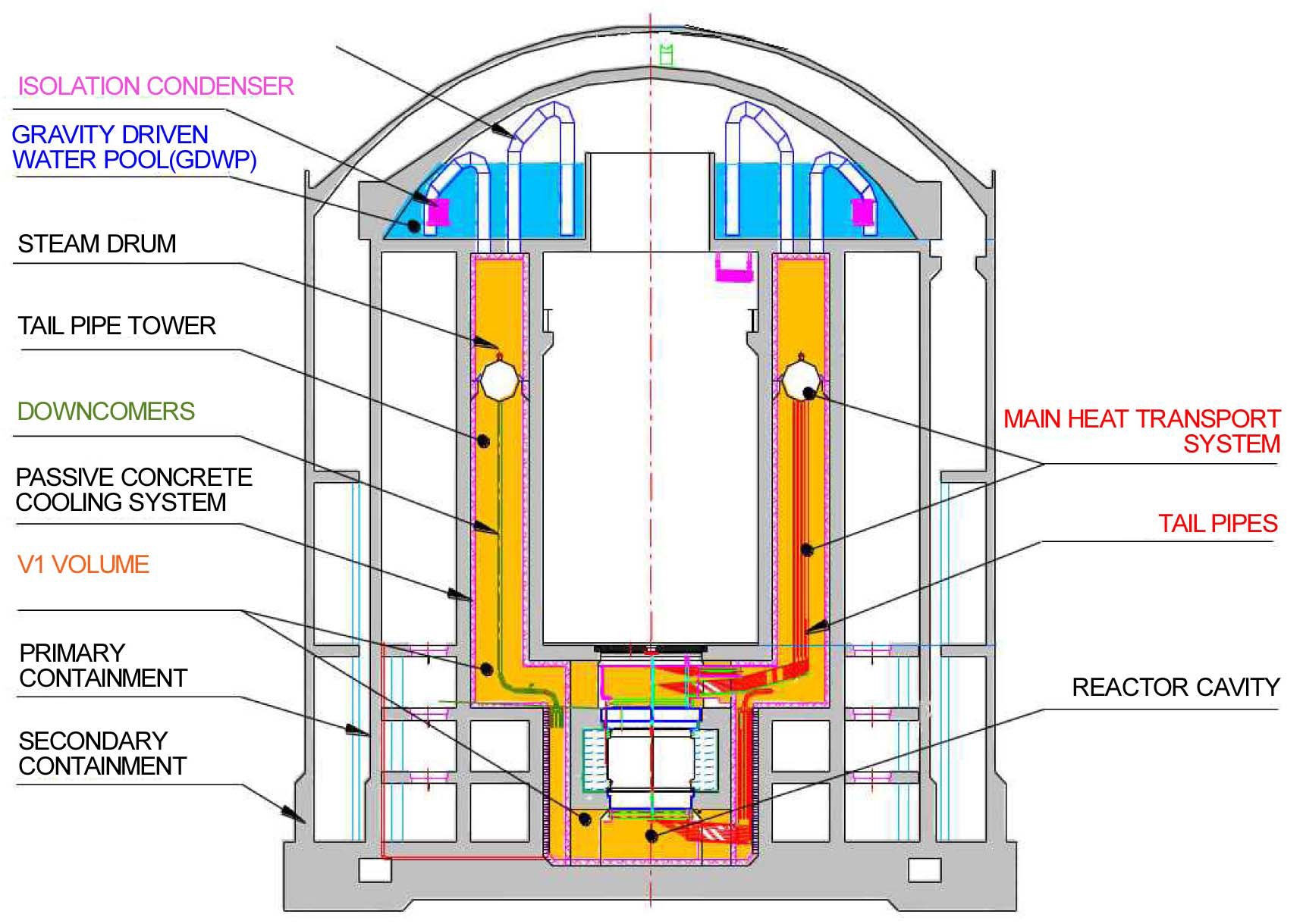
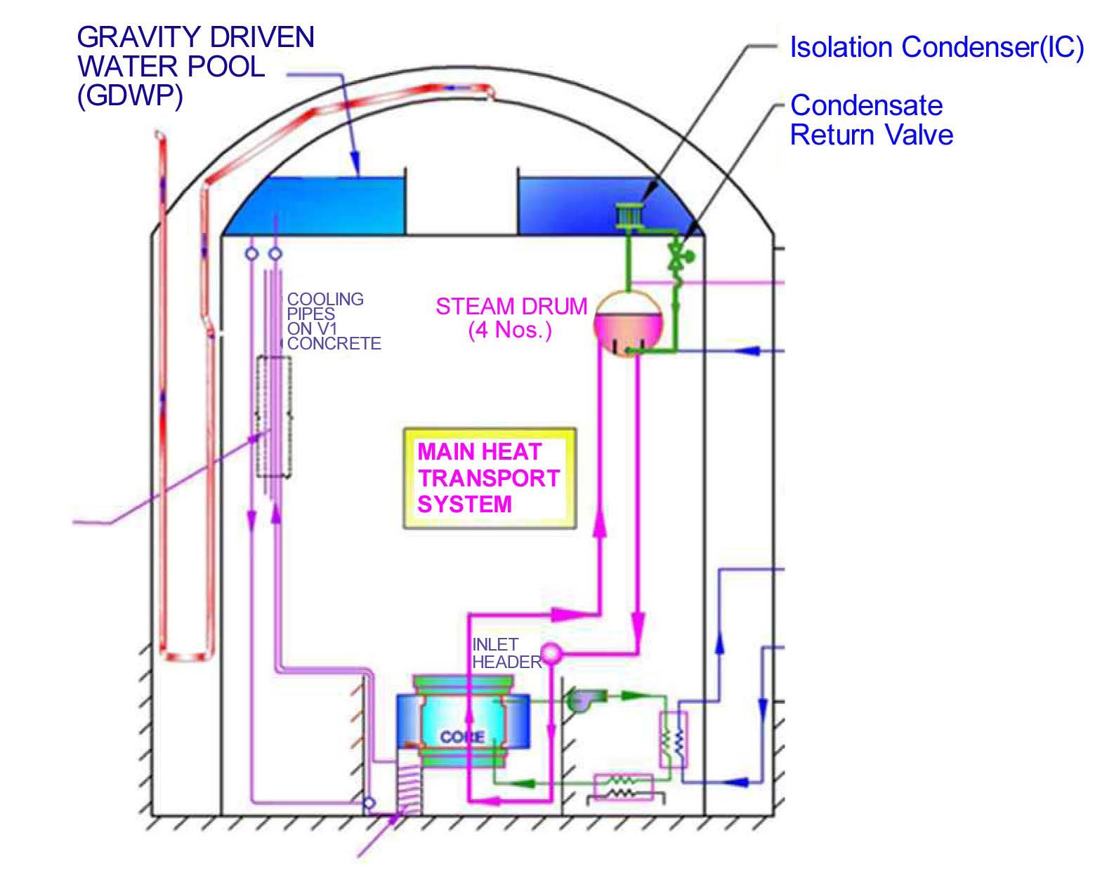
shows the general arrangement of MHTS and ICS of AHWR whereas 1b shows the AHWR primary containment.
Main Heat Transport System (MHTS): The main heat transport system consists of a vertical core which houses 452 coolant channels. Subcooled water from the steam drums enters each of the channels through the inlet header. Boiling takes place in the channel due to the addition of fission heat and the two-phase mixture is carried to the steam drum (4 nos.) through corresponding tailpipes. The steam drum is a horizontal cylindrical vessel with appropriate internals kept at an elevation of 32.5 m with respect to the axial center of the core, where gravity separation of the two-phase mixture is achieved. Nearly dry saturated steam leaves the steam drum through steam lines to feed the turbines. Recirculation water is mixed with feed water in the steam drum and it flows to the header through the downcomers (4 nos. per steam drum).
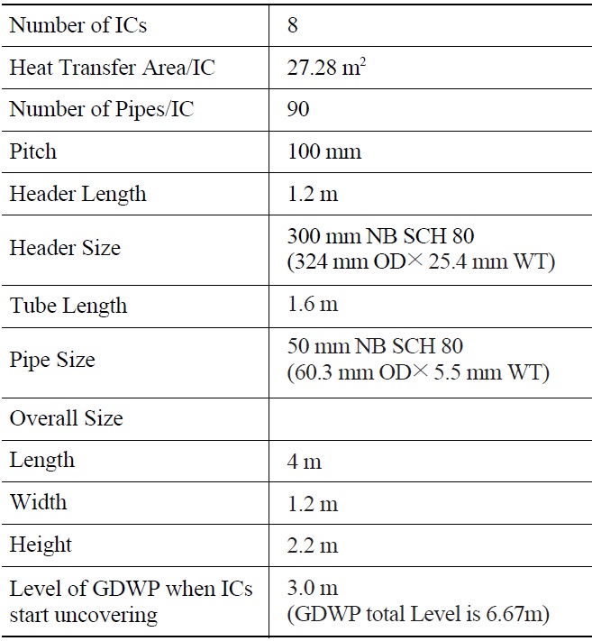
Isolation Condensers: The Isolation Condenser System comprises of a set of immersed condensers located in an elevated water pool called the Gravity Driven Water Pool (GDWP), and associated piping and valves. The GDWP holds a huge inventory (8000 m3) of water kept on the top of the steam drums of the reactor. The relative elevation of the GDWP with respect to the core is 50.5m. Table-2 shows the important parameters of isolation condensers.
A branch connection from the steam line carries the steam to the tube bundle of the immersed condenser through a distributor and top header. Steam condensation takes place in the tube bundle and the condensate returns to the steam drums through a bottom header and condensate return line. The condensate return line is provided with a
[Table 2.] Important Parameters of Isolation Condenser

Important Parameters of Isolation Condenser
set of active and passive valves in parallel. The opening of a passive valve is regulated passively depending on steam drum pressure. This valve opens when the system pressure exceeds 76.5 bar and becomes fully open at 79.5 bar. This valve is a self-acting single-port spring-loaded valve with pressure balancing by stainless steel bellows, working in proportional mode requiring no external energylike pneumatic or electric supply for its actuation. The valve uses the steam drum pressure as the signal and has the linear characteristic, i.e. valve opening varies from fully closed to fully open with the variation of steam drum pressure in the specified range. The active valve is pneumatically operated which is provided in parallel to the passive valve. This valve opens at 79.5 bar or in case of failure of the pneumatic supply, which takes roughly 30 minutes after the occurrence of SBO irrespective of the MHT pressure. Under normal operation these valves remain closed, thus isolating the ICS from the MHTS, and steam flows to the turbine circuit. However, under SBO conditions the steam and feed systems are isolated from the MHTS. When the MHTS pressure rises, the passive valve opens in response to steam drum pressure and the active valve opens 30 minutes after the occurrence of the SBO due to the decrease of compressed air pressure.
Emergency Core Cooling System:
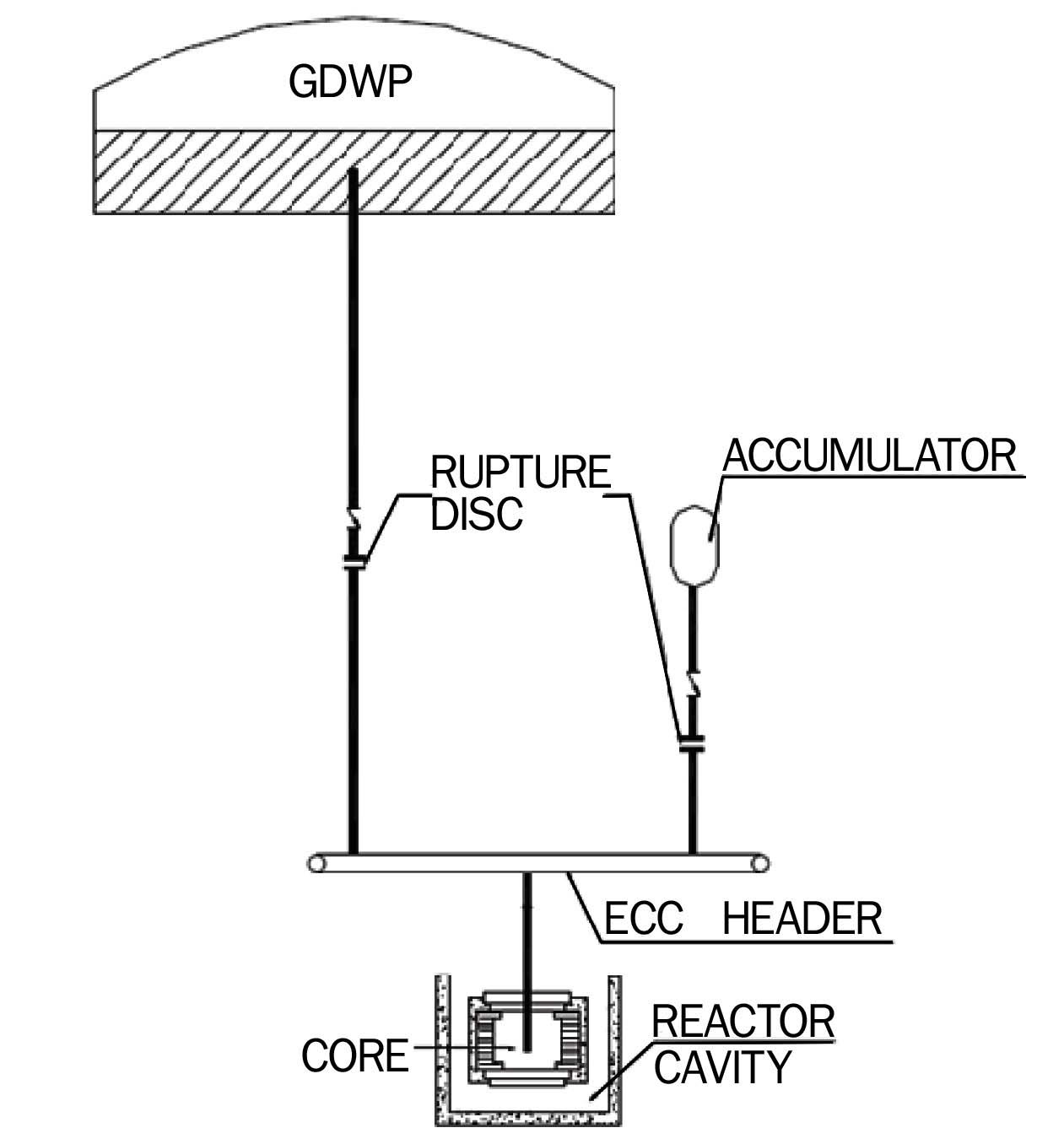
This system provides for the injection of water directly into the reactor core in three stages. In the first stage, injection from the accumulator takes place when the pressure in the MHTS falls below 50 bar. In the second stage, water flows from the GDWP under gravity when the MHTS pressure falls below 3 bar, providing core cooling for three days. In the third stage, water accumulated in the reactor cavity is pumped back to the GDWP, from which it eventually enters the core. The first and the second stages of ECCS are passively actuated and do not depend on any active component. The important components of the ECCS are the GDWP and accumulators as shown in Fig-3.
Containment Cooling System:
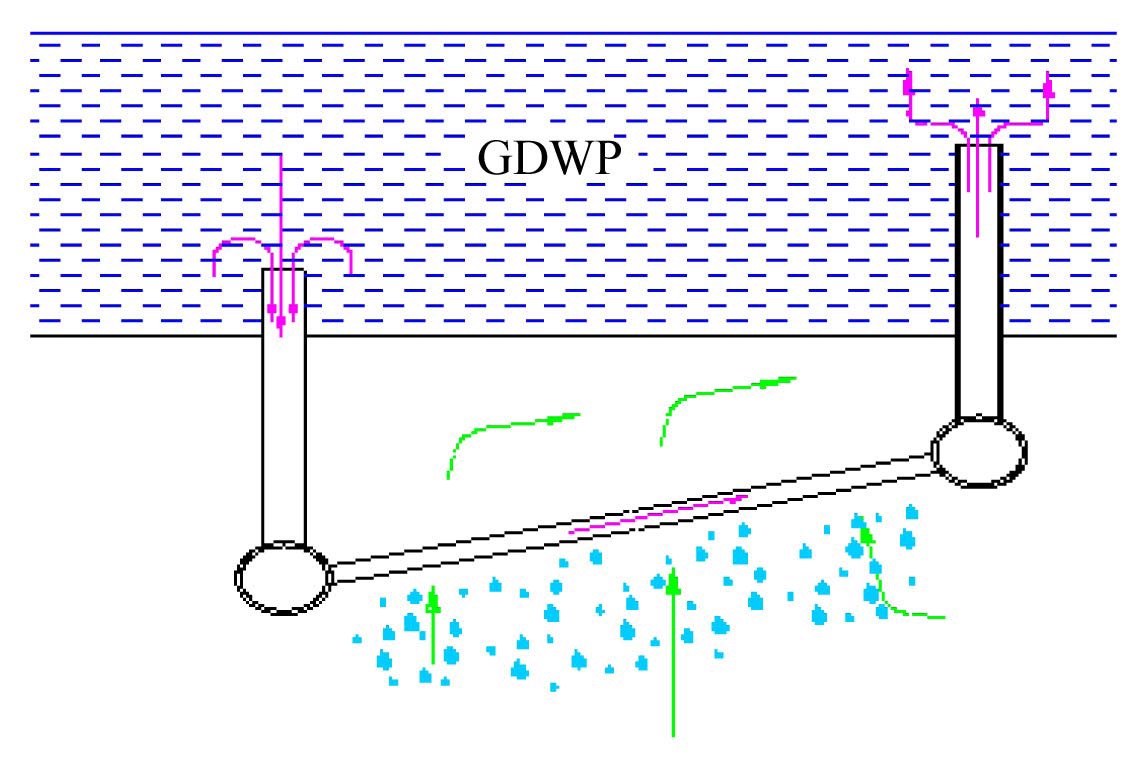
The containment cooling system comprises of three passive components viz. suppression pool, containment wall having large surface area, and Passive Containment Coolers (PCCs). The PCCs are located below the GDWP and are connected to the GDWP as shown in Figure 4. During a LOCA, condensation of steam and cooling of hot air are achieved on the cold walls of the containment and on the PCC tubes by natural convection of GDWP water which flows through the PCC tubes. This design feature ensures long term containment cooling after an accident.
Various systems of the reactor viz Main Heat Transport System (MHTS), Isolation Condenser System (ICS), Emergency Core Cooling System (ECCS), Passive Containment Cooling System (PCCS), and Primary Containment volumes, i.e. V1 and V2, are integrally simulated with the system code RELAP5 Mod3.2. RELAP5 Mod3.2 has also been used to simulate natural circulation in integral test facilities [6]. Initially, steady state is obtained for MHTS and the containment volumes V1, V2 and ECCS are initialized as per the initial conditions given in Table-3.
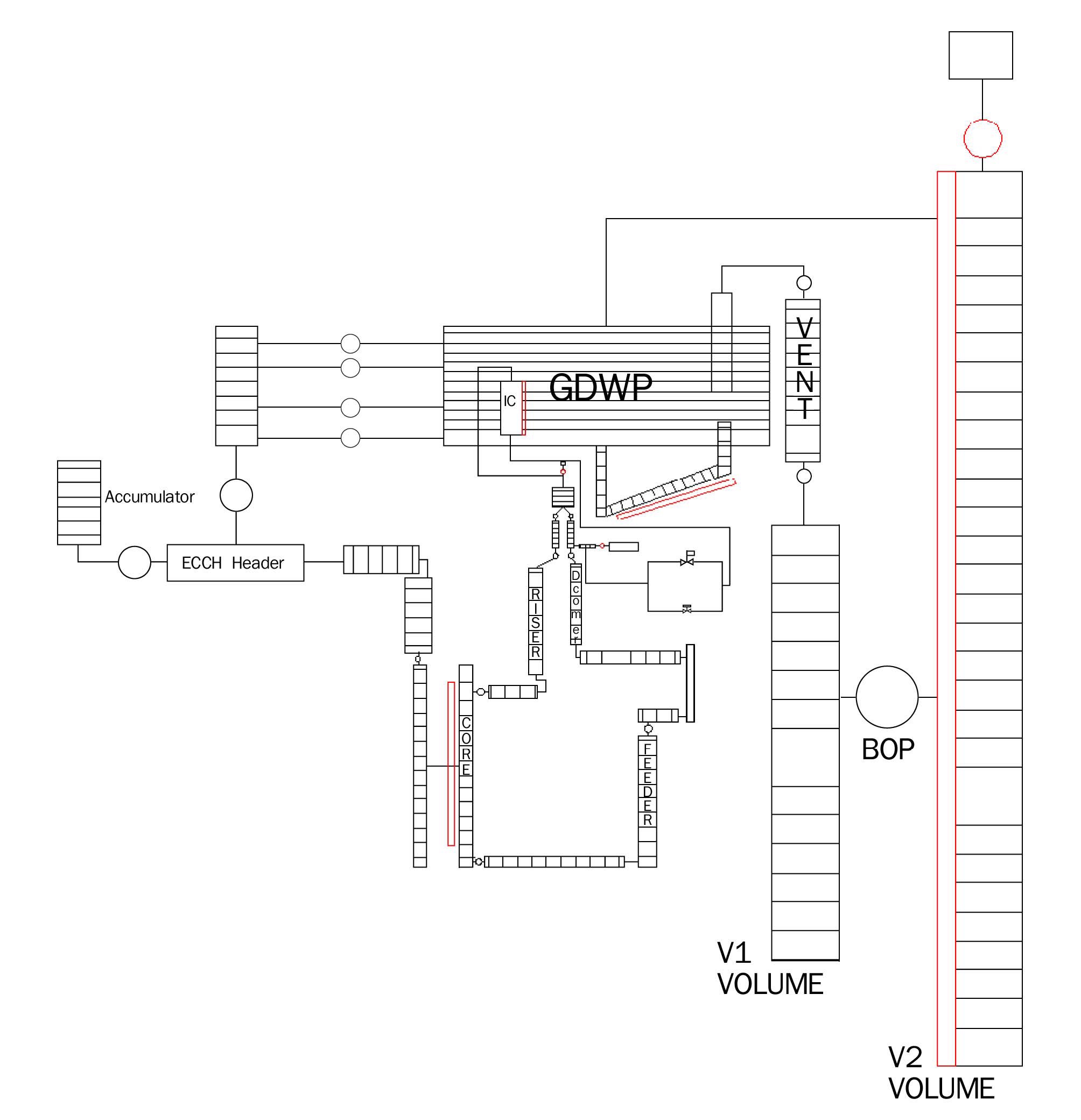
Fig 5 shows the RELAP5 Nodalisation of the various systems of the reactor. All the channels in the MHTS are grouped as a single equivalent channel having the total flow area and heat transfer area, generating the full power. This channel is connected to a single equivalent feeder of the 452 feeders of the reactor and a single equivalent tail pipe of the 452 tail pipes of the reactor. The four steam drums are combined into an equivalent steam drum. Similarly all the downcomers are modeled as an equivalent downcomer which is connected between the header and steam drum. All the tubes in the ICS are combined into an equivalent tube connected between the headers of the ICS. Five axial nodes are taken for IC tubes, which are associated with heat structure. The GDWP is connected to the containment volume V2 since the GDWP is situated at the top of the
[Table 3.] Initial Operating Conditions for Various Systems of the Reactor
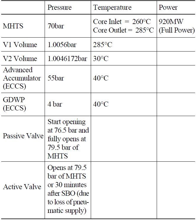
Initial Operating Conditions for Various Systems of the Reactor
containment. The two containment volumes are initially isolated from each other and filled with air at the normal operating condition as shown in Table-1. The containment volume V1 is modeled without heat absorbing capacity, while volume V2 is modeled with heat absorbing capacity. In order to estimate the heat transfer to the containment wall during condensation, the heat structure associated with the containment volume V2 is divided into 21 mesh points. The first 5 mesh points are 5 mm wide and the next 5 mesh points are 10 mm wide. This is followed by 5 mesh points of 25 mm width and 6 mesh points of 322.5mm. Since concrete has poor thermal conductivity and high heat capacity, the nodalisation considered in the radial direction gives a more accurate prediction of condensation on the V2 volume wall than considering an average one, so to account for the realistic rate of heat transfer relatively fine nodalisation is taken.
A prolonged SBO condition has been considered for analyzing the decay heat removal capability of the reactor. The cause of the SBO is postulated to be a strong earthquake followed by a Tsunami which may cause the SBO. With initiation of the earthquake, the reactor is safely shut down on the seismic signal. The turbine is tripped which causes closure of CIESV and the feed water supply line is also isolated at the same time due to unavailability of feed pumps. Thus, the MHTS becomes boxed up, which causes the pressure of the MHTS to start rising. When the pressure of the MHTS reaches the set point of the passive valve of the Isolation Condenser (IC), i.e. 76.5 bar, the ICS gets valved in. Due to unavailability of the power supply, the pneumatic pressure is lost after 30 minutes, which causes the active valve in the ICS to remain continuously open. If the pressure of the MHTS falls below 50 bar, ECCS injection from accumulators starts and continues until the level in the accumulators falls below 75 cms which is a low level isolation of accumulator. If the MHTS pressure does fall below 3 bar then injection from GDWP may start injecting water into the core.
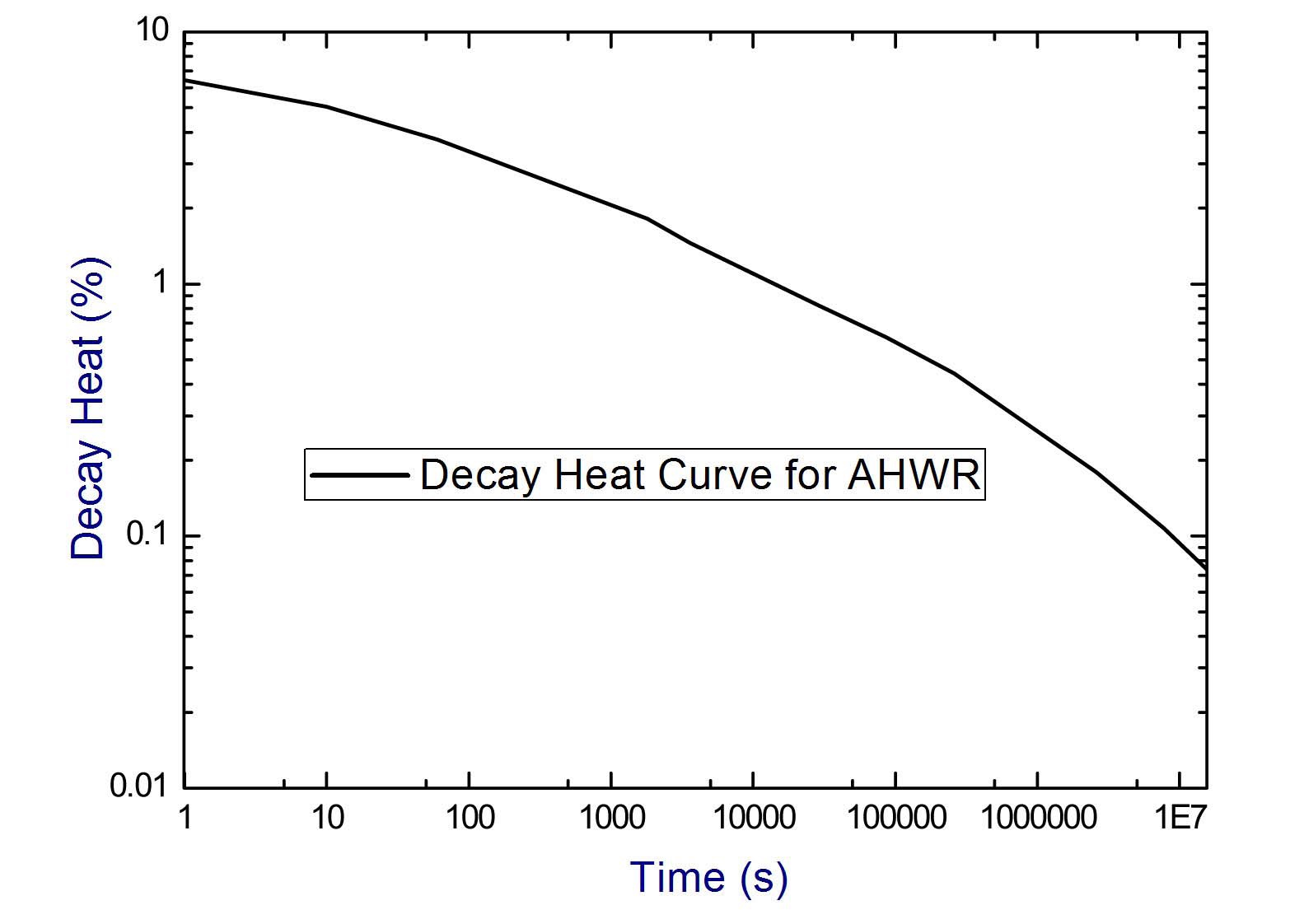
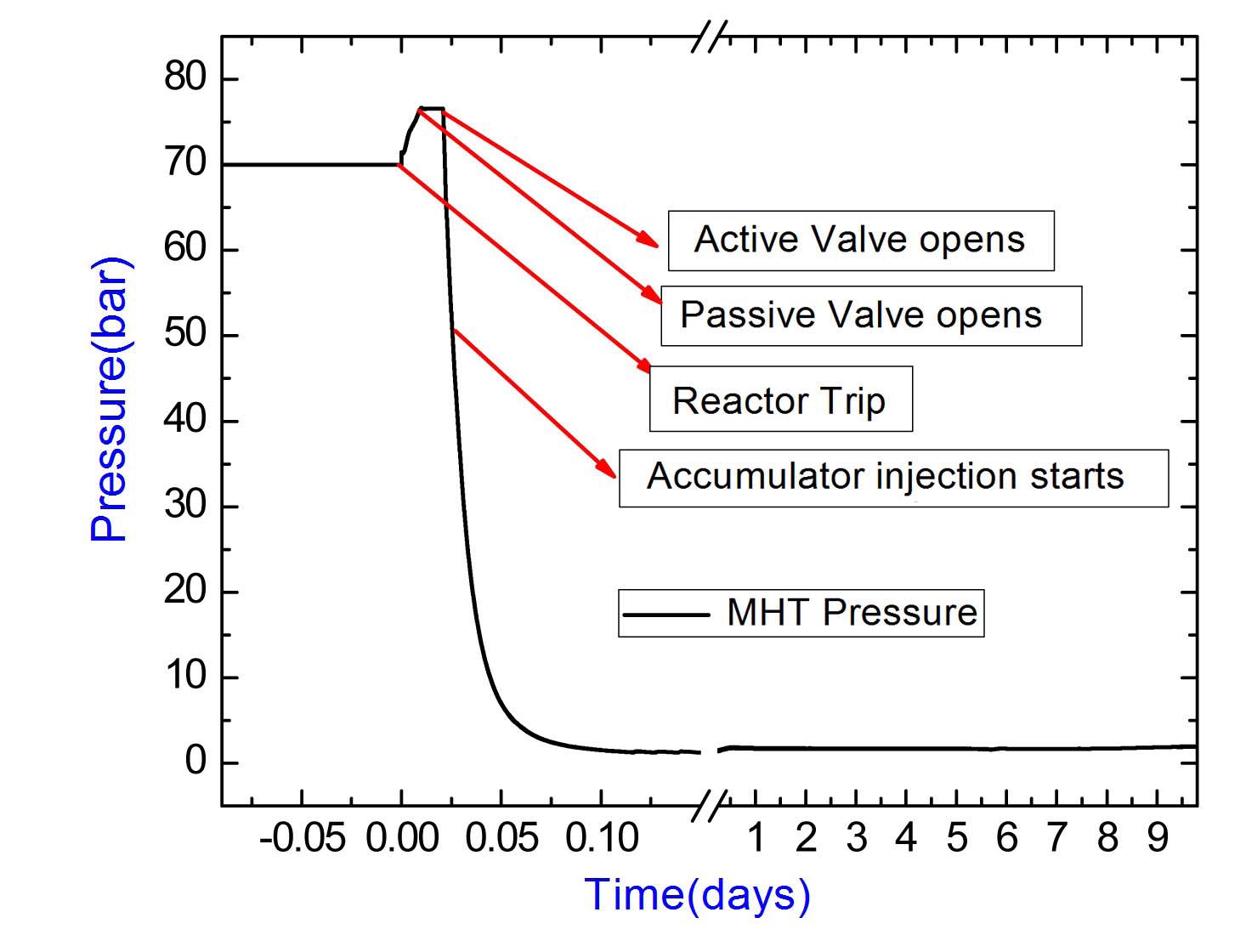
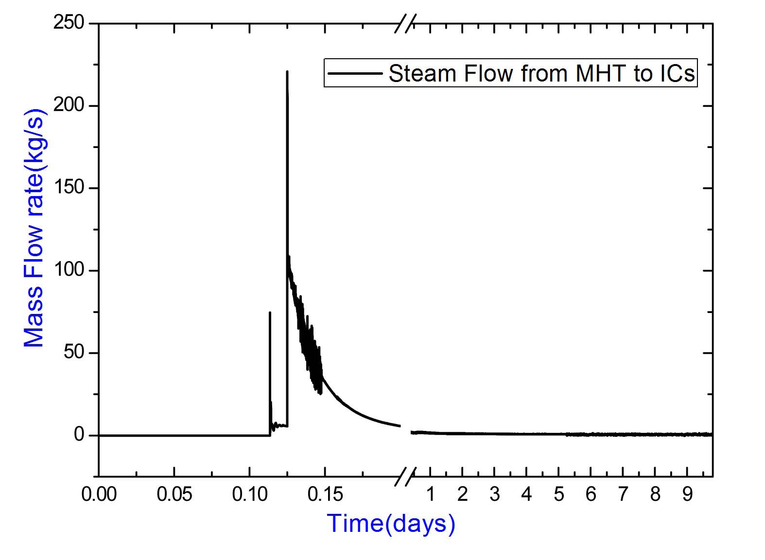
Figures 6 and 7 show the variation of decay power and MHTS pressure respectively. At time t=0 s, the reactor trips on the seismic signal. Due to a rise in pressure, the passive valves open at 76.5 bar after nearly 600 seconds. The steam generated in the MHT system is condensed in the ICS and this causes the pressure in the MHT to remain more or less constant. Figure 8 shows the steam flow rate from the MHT to the ICS. The flow rate is initially higher due to larger decay heat, which reduces continuously due to reduction of decay heat with time. The active valve opens after 30 minutes, which helps a larger flow rate of steam into the ICS. This causes rapid condensation of steam resulting in progressive decrease of MHT pressure. At around 45 minutes, the MHT pressure falls to the set point
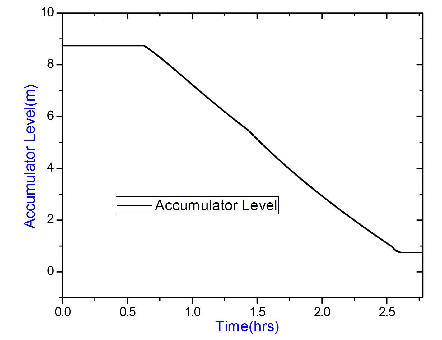
of the accumulators and cold water is injected into the core passively. At about 2.5 hrs., accumulator injection stops due to the low level of accumulators (Figure 9). The MHT pressure remains well above the inject set point of GDWP. As a result no injection from GDWP occurs during the whole transient.
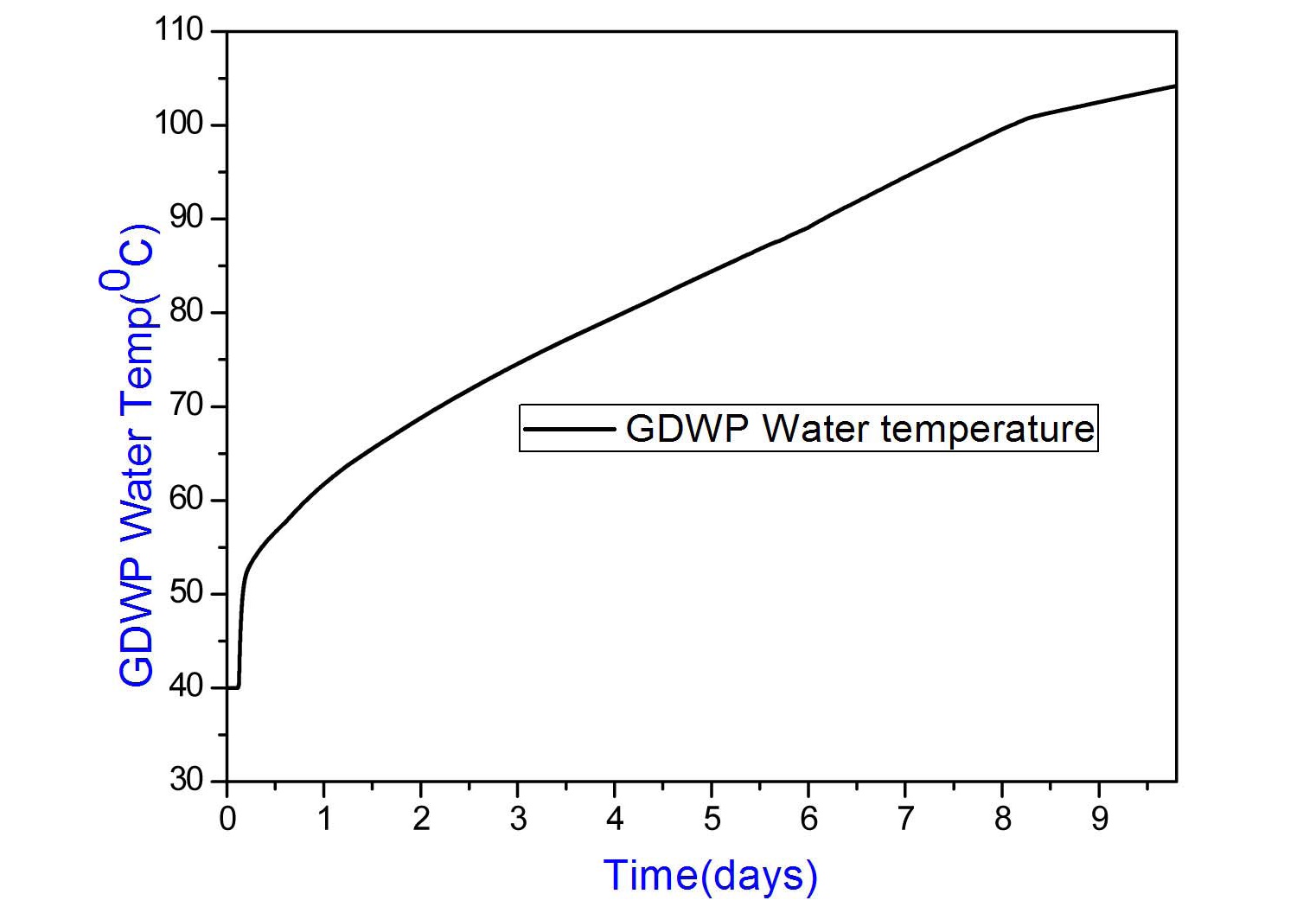
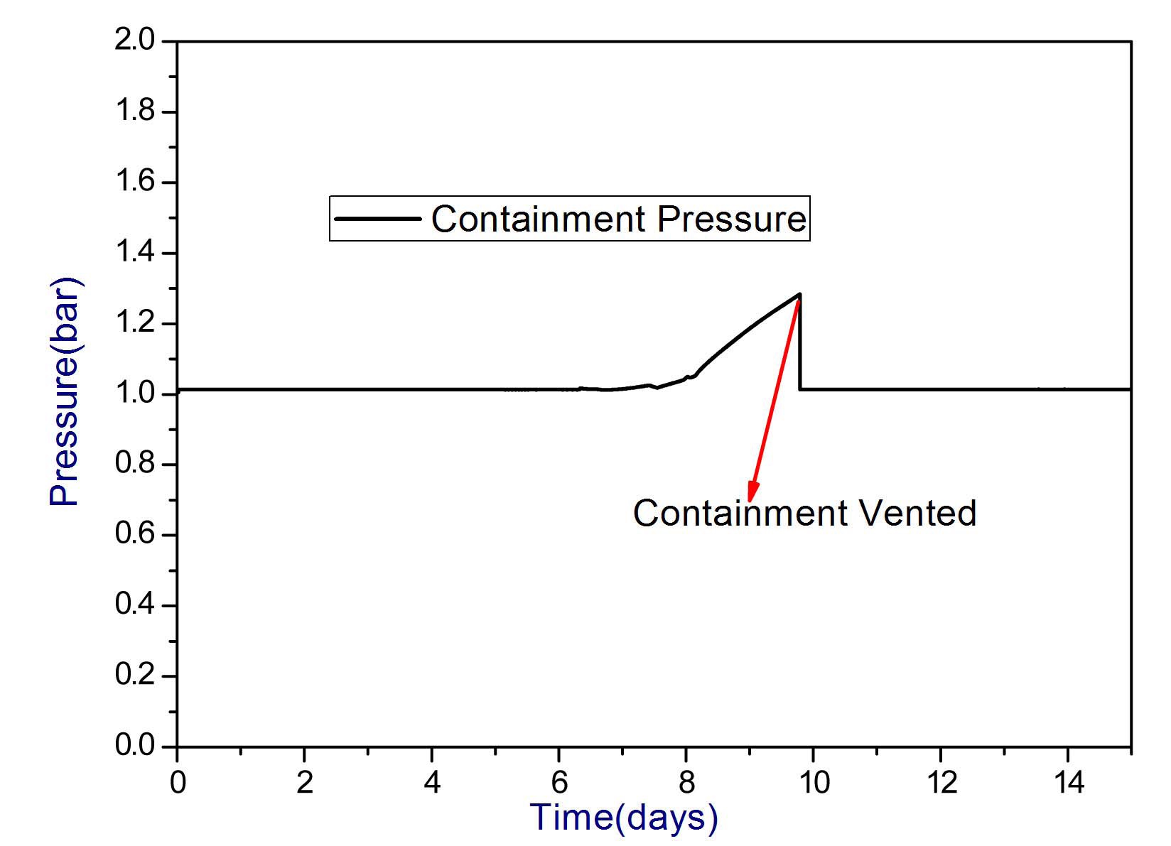
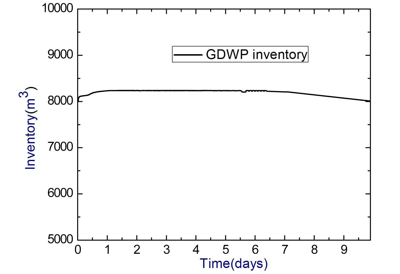
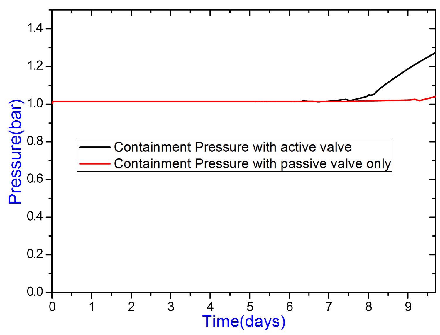
The rise in water temperature in GDWP is shown in Figure 10. It can be seen from Figure 10 that there is an initial surge in GDWP water temperature, which is due to the high decay heat just after reactor shutdown. It reaches the saturation temperature at atmospheric pressure after nearly 8 days. After this period, boiling occurs in the GDWP causing the pressure to rise in containment (Figure 11). Due to the rise in containment pressure, the GDWP saturation temperature also increases as seen in Figure 10 since it is exposed to the V2 volume directly. The containment pressure rises to nearly 1.3 bar after more than 10 days of the accident, which is far below the design pressure of the containment. The volumetric inventory of water in the GDWP is shown in Figure 12. It is observed that there is still more than 7500 m3 of water in the GDWP even after 10 days of the accident.
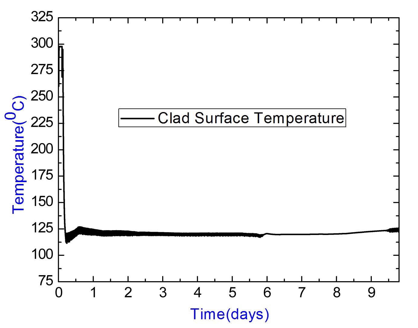
The variation of clad surface temperature is shown in Figure 13. The clad surface temperature falls below 125 deg C after such a long transient, which implies that the passive systems are capable of cooling the fuel with sufficient margins for such a prolonged period.
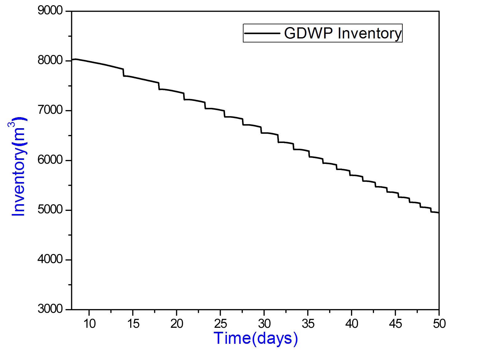
If containment venting is carried out after 10 days of the accident, the decay heat is removed by ICS by boiloff of the GDWP water. Results show that there is still
more than 4500 m3 of water in the GDWP even after 50 days of the accident (Figure 14). The clad surface temperature also remains well below the operating temperature during this period (Figure 15).
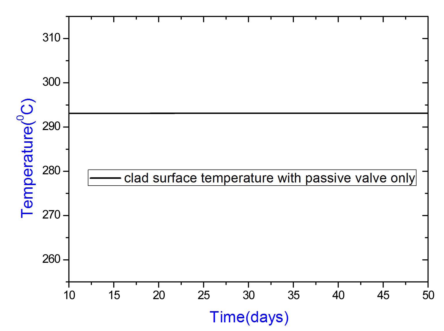
Analysis has been repeated for the decay heat removal capability of - AHWR using the ICS assuming the active valves fail to open, for a 10 day period. In this case, the connection between the ICS and MHT is established by
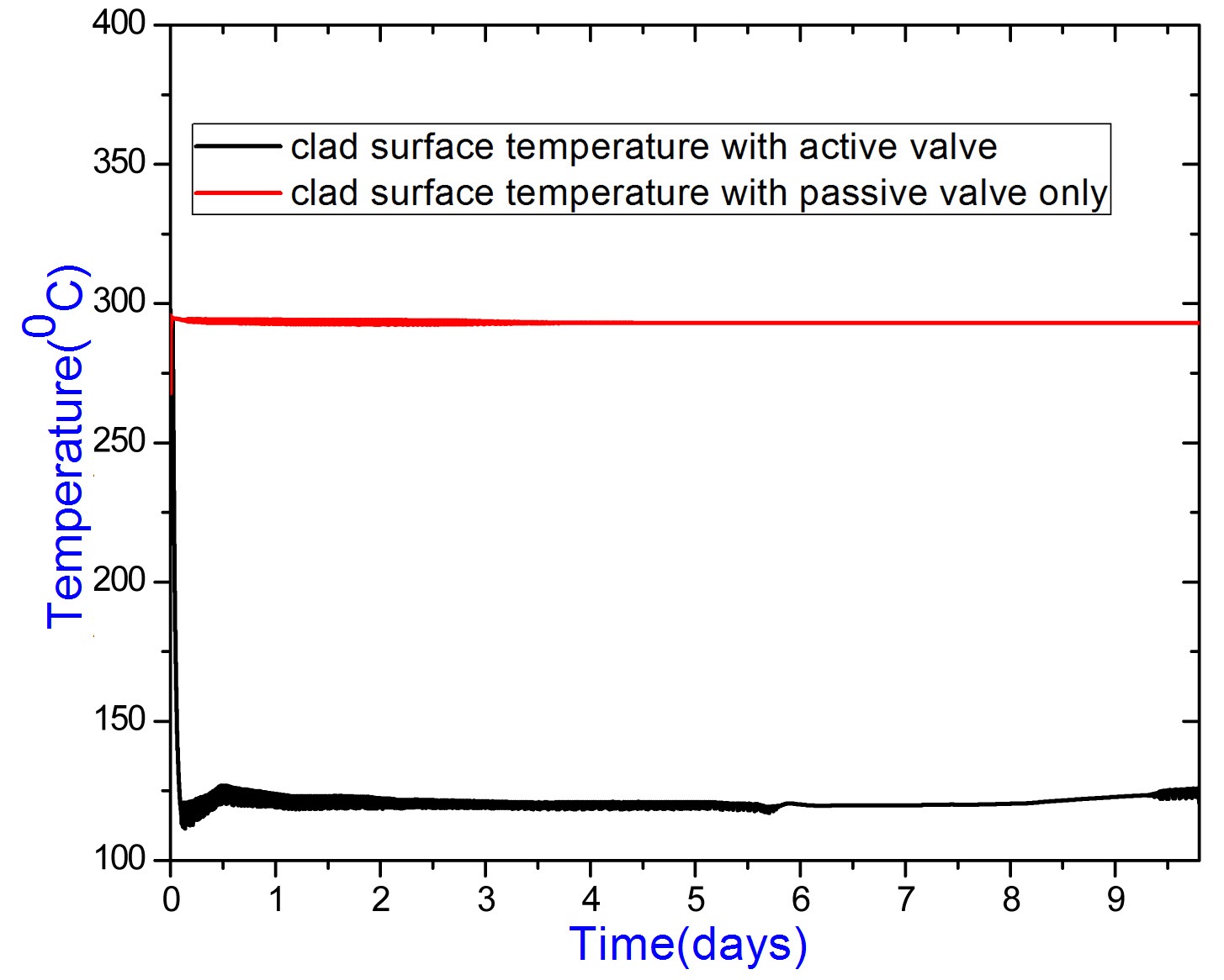
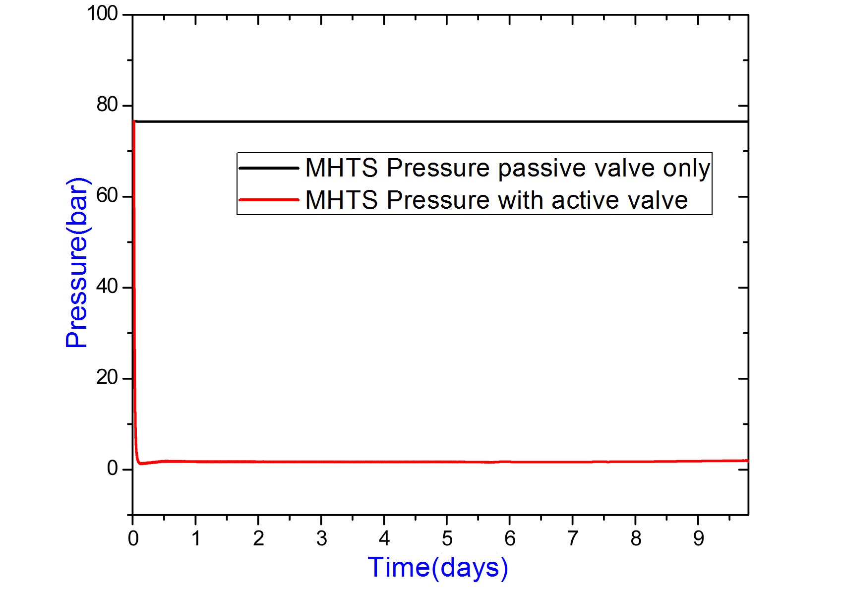
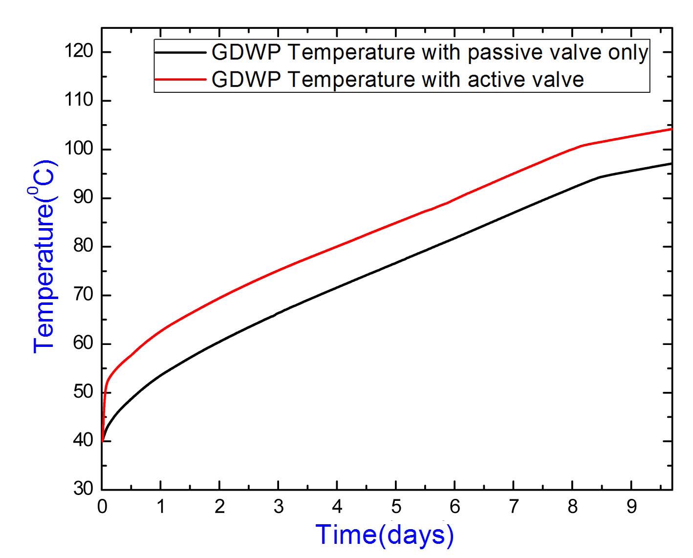
passive valve only, which opens at 76.5 bar. Unlike the active valve, this valve closes if the MHT pressure falls below the above pressure. As a result of which, the MHT pressure is found to remain more or less constant during the transient (Figure 16). Variation of water temperature in the GDWP is more or less similar to the previous case (Figure 17), except in the initial period when a larger flow of steam occurs into the ICS than the former case since
both active and passive valves are open. The clad surface temperature is well below the safety limit during the whole transient (Figure 18). The temperature is more or less constant, but it is higher compared to the previous case since no ECCS injection occurs in this case. Even after 10 days of the accident, the containment pressure is around 1.0316 bar which is roughly the same as the previous case as shown in Figure 19.
Considering the concerns of nuclear reactor safety after the recent Fukushima accidents, a safety analysis has been performed for AHWR for a prolonged SBO condition of several days without invoking any operator actions. Results indicate that the Isolation Condensers are capable of removing the decay heat of the reactor by passive means with sufficient safety margins. The clad surface temperature was found to remain well within the safety limits during the whole transient. The large pool of water in the GDWP plays an important role in such a situation, since it is able to absorb the decay heat from the Isolation Condensers for more than 50 days. The containment pressure hardly reaches to 1.3 bar even after 10 days of accident. If venting is carried out after this period, the reactor can safely diffuse the decay heat by passive means for more than 50 days without any concerns with regard to fuel temperatures.