All industrial plants undergo changes over time, and nuclear plants are no exception. The CANDU 6 reactor follows earlier CANDU designs such as NPD (Nuclear Power Demonstration), Douglas Point, Pickering A, and Bruce A. As such, certain aspects of plant aging were addressed directly in the design process. This was reflected in the selection of the materials, design allowances and provisions, and operating margins. In addition, certain maintenance practices have been developed over time at the stations to address the aging issues. In terms of Special Safety System availability, Reliability Studies were performed to determine the required tests and frequency of testing to ensure that necessary targets were achieved. Nonetheless, it was not possible to precisely predict how the plants would change over time at the design stage. To ensure that such changes would not compromise public safety, programs were developed to provide a continued assurance of Nuclear Station Safety.
These programs are based on the principles of monitoring/ detecting, anticipating, understanding and then correcting or compensating. It has components involving Research and Development (R&D), analysis and assessment, maintenance, operational changes, and design modifications.
This paper deals with the investigation of the aging behavior of the heat transport system (HTS) for an older CANDU 6 plant as well as newer, improved plants and its potential impact on safety systems including the performance of channel flows and Critical Channel Power (CCP), one of the major components in the Regional Overpower Protection (ROP) system. This safety system protects against slow Loss of Regulation (LOR) accidents.
This paper further explores, in greater detail, post-CCP aging safety analysis methodology for a fresh core and an 11 EFPY aged core for the case of a postulated feeder stagnation break, and specifically includes fuel failure and the fission gas release during an accident transient which plays a major role in determining possible radiation doses to the public after postulated accidents have occurred.
2. CANDU 6 MAIN HEAT TRANSPORT SYSTEM AGING
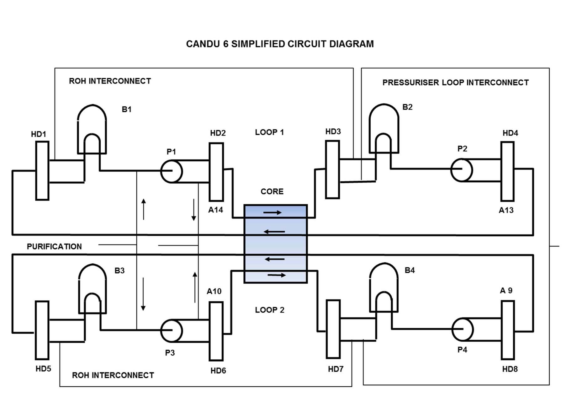
Fig. 1 gives a simplified presentation of the HTS components and coolant flow of a typical CANDU 6 reactor. The HTS consists of two “figure-of-8 loops” with four main HTS pumps (P1, P2, P3, P4), four Steam Generators (SG) (B1, B2, B3, B4), and associated headers (HD) servicing the 380 reactor-core channels (ranging from channels A09 to W14). Each HTS loop consists of two HTS passes. The outlet header, purification and pressurizer interfaces are also shown.
Operational preferences as well as aging processes may cause changes to the primary HTS. These changes affect both the coolant-flow and heat transfer properties of the HTS as a whole. There are several contributing effects, some acting to increase and some to decrease the safety margins. The magnitudes of these effects vary over time, and thus the overall impact on the HTS is a complex integrated function of all mechanisms.
Operational changes can take place in a relatively short time frame, such as changes caused by utility operating preferences as well as changes in the reference analytical model interpretation caused by measurement-instrumentation calibration.
Aging related changes typically take place over relatively long time periods. The following is a list of the main known aging processes that may occur within the HTS that can influence the CCP:
Increase in Pressure Tube (PT) diameter owing to irradiation creep (PT diametral creep): This reduces
the hydraulic resistance in the channel, and hence increases its coolant-flow, but causes a redistribution of coolant flow within the bundle that can result in a reduction in dryout power. Because there is more creep in the higher power channels, there is a flow redistribution effect whereby some of the flow from the outer low power channels is redirected to the inner channels. Increased flow in the central channels mitigates the effect of PT diametral creep on the CCP for the central most important, high-power channels.
Increase in hydraulic resistance owing to a redistribution of iron oxides (magnetite) in the HTS: Dissolution of iron and Flow Accelerated Corrosion (FAC) has been shown to occur in CANDU 6 plants. Iron is removed from the outlet feeders and is re-deposited in the cooler parts of the circuit, including the cold leg of the steam generators, the inlet feeders, and possibly the first section of the fuel channels. The magnetite layers cause both a fouling of the inside of the steam generator tubes, leading to reduced heat transfer, and also an increase in hydraulic resistance in the steam generator tubes and inlet feeders. This affects the core flow (possibly also the core top-to-bottom flow tilt), inlet header temperature, and consequently, the CCP.
Erosion of the edges of flow-reducing orifices: This leads to relative flow redistribution from the inner to the outer parts of the reactor core.
Considerable advances have been made to mitigate these aging characteristics, by making both design and operational changes.
3. SITE MEASUREMENTS FOR REACTOR PERFORMANCE TRACKING AND HTS MODEL DEVELOPMENT
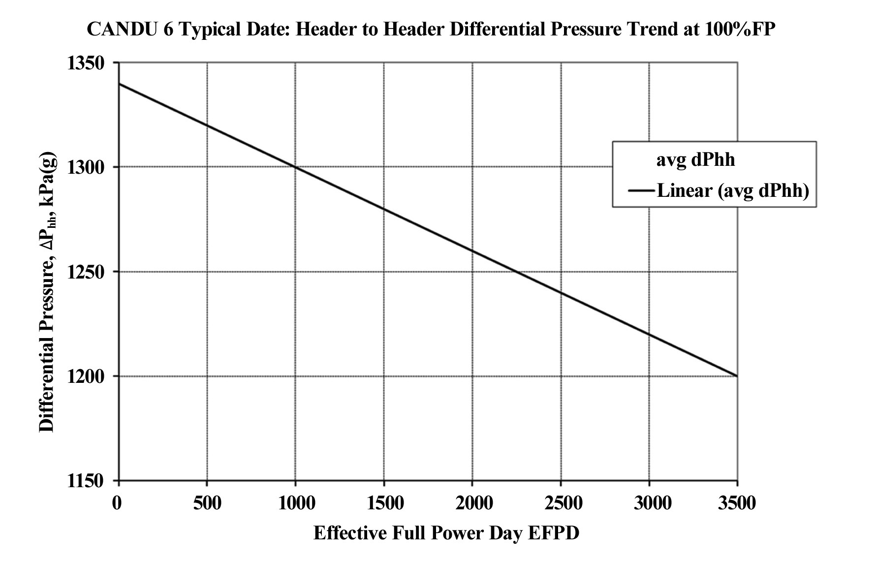
CANDU 6 plants keep track of key measurable parameters as a means of tracking the aging of the plant, and make adjustments as appropriate. Typical site data measurements include inlet header temperature, header-to-header differential pressure, outlet header pressure, pump suction pressure, coolant flow rate, and PT diametral creep. Some of the aging trends associated with these parameters are captured in Figs. 2,3, and 4 for the original design while Figs. 5,6, and 7 summarize corresponding typical data for newer plants with significantly improved operating characteristics. Similar site specific data are included in References [1] through [6]. The careful selection of variables used to define the HTS component aging, allows analysis code based HTS component aging models to be generated in terms of HTS component geometries, the SG and HTS pump performance, and purification flow (References [7]).
During the design stages, HTS models are generated from the known HTS component geometry and performance, as supplied by the component manufacturers. An analysis of the aging trends is generally limited to bestestimate PT diametral creep predictions (References [8]) although conservative estimates may be used for the SG,
reactor core feeder roughness, and inlet feeder flow-reducing pressure break-down orifice aging.
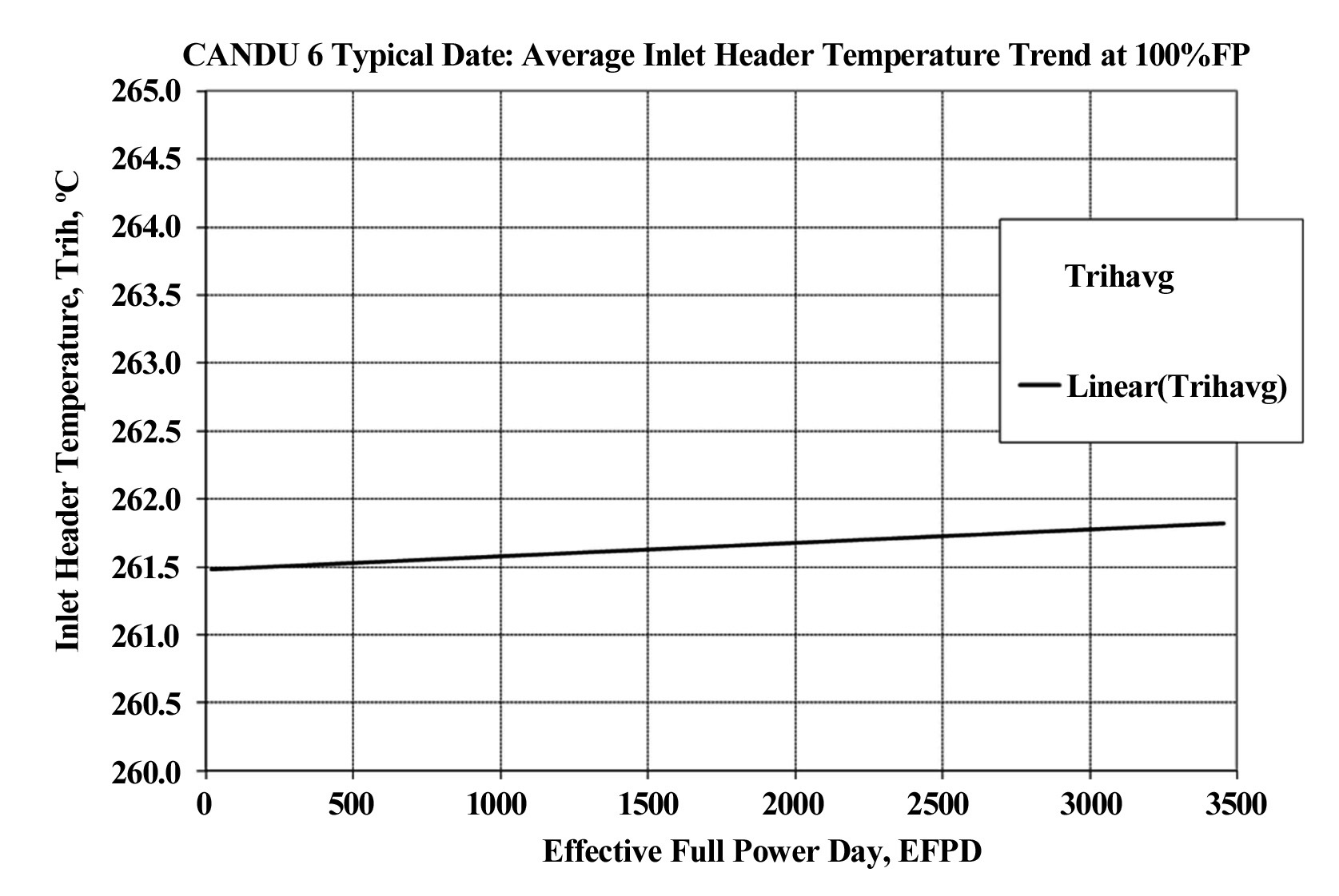
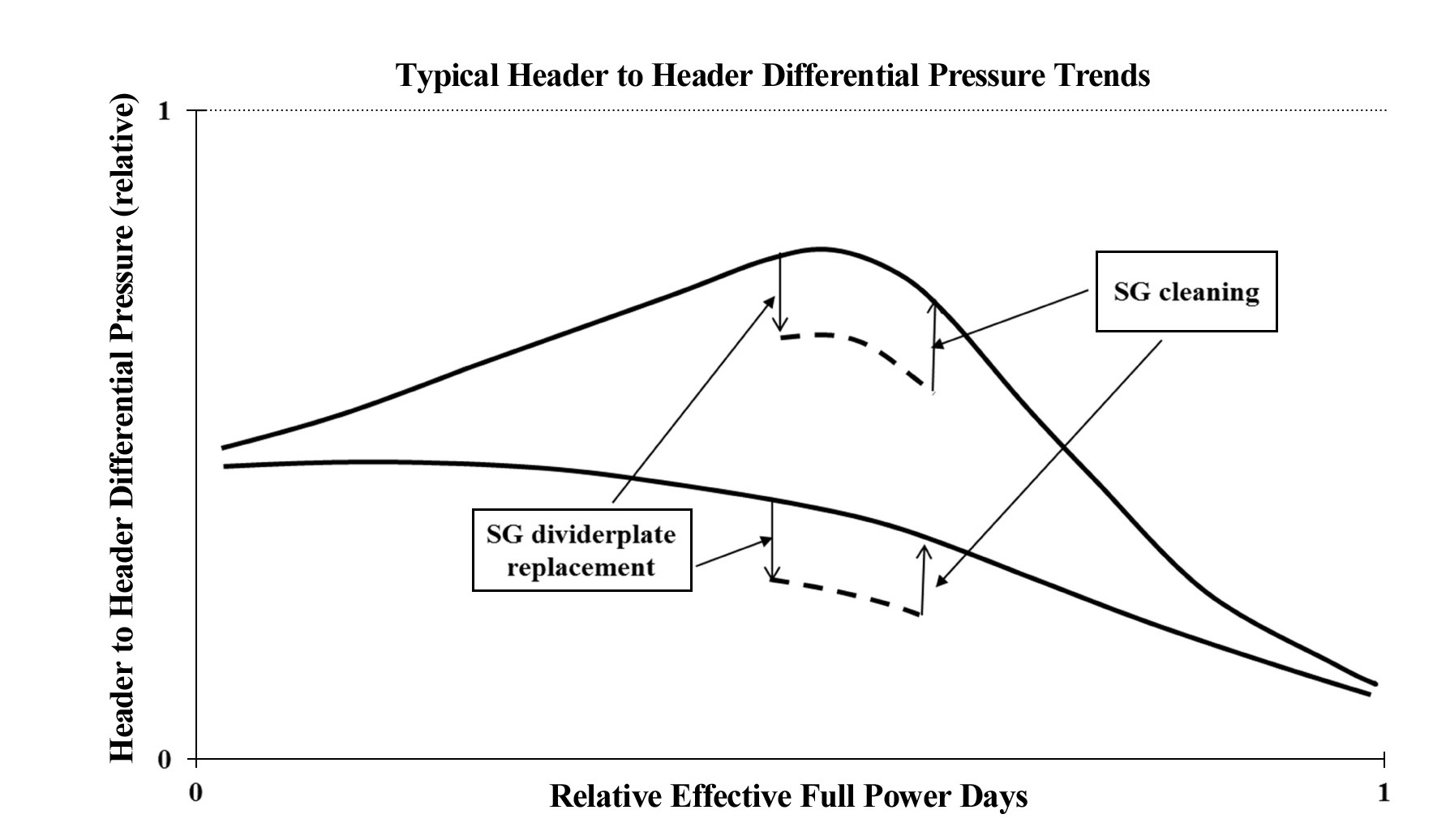
As the HTS ages, the main tracked parameters of temperature, pressure, coolant flow resistance (based on the coolant flow rate), and core flow distribution may change considerably over time. These four main tracked parameters are affected by the aging of all HTS components. SG aging not only reflects the inlet header temperature trend (Figs. 2 and 5) and SG flow resistance trend (Figs. 4 and 7), but also the header to header differential pressure trend (Figs. 3 and 6), which, together with the core flow rate, defines the reactor core hydraulic characteristics. Analyzing at different historical times will allow the determination of trends associated with the reactor HTS component aging. These trends can then in turn be used to predict the best estimate HTS operating conditions at future operating points, forming the bases for safety analyses at specific future reactor operating points.
Depending on the application requirements, the HTS component model evaluations may have considerable detail. The SG modelling may be used to predict the performance of the SG for the given geometrical and thermal-hydraulic characteristics or determine the parametric curves that define the relationships between the inner tube diameter,
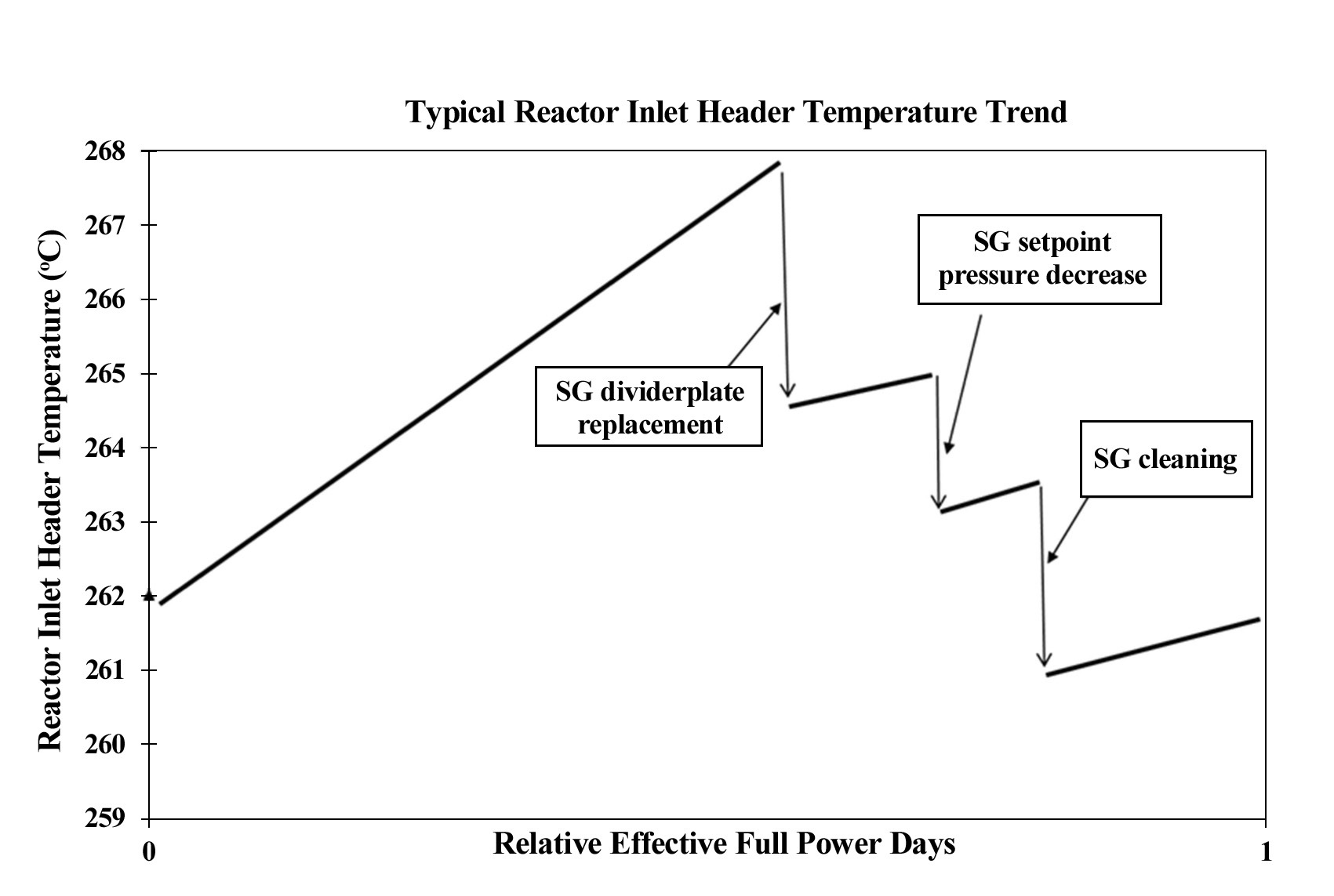
tube roughness, tube fouling, tube plugging, divider plate leakage, thermal plate leakage, recirculation ratio and primary separator pressure drop. As the plant ages, the SG exhibits aging signs in terms of these parameters. Consequently, the inlet header temperature (Figs. 2 and 5) increases mainly from two effects:
Lower heat transfer coefficients in the SG tubes as residual builds up; and
Divider plate leakage which leads the coolant flow to by-pass the SG tubes.
These two effects are overcome by SG cleaning and SG divider plate replacement respectively. Correspondingly, the inlet header temperature drops as noted in Fig. 2. Inlet header temperature may also drop due to secondary side SG setpoint pressure decrease, an operational option, as shown in Fig. 2 as well.
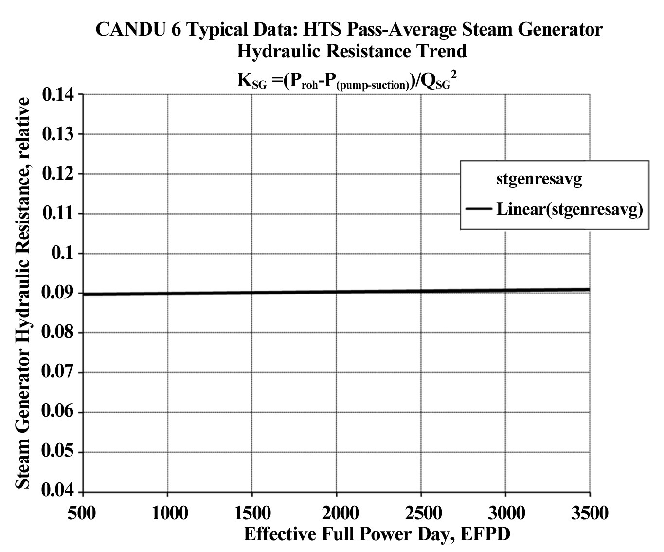
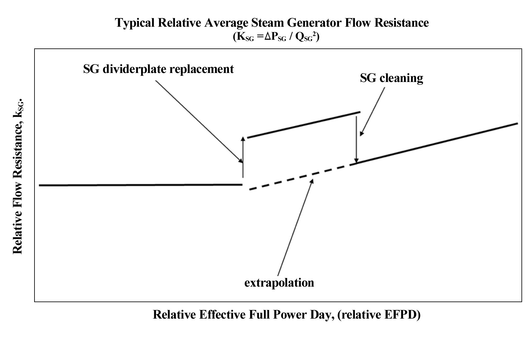
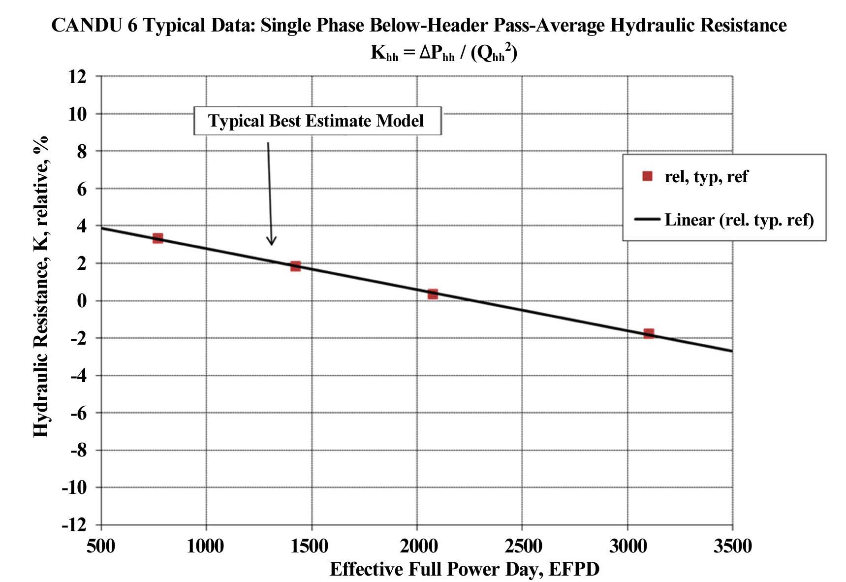
Hydraulic or flow resistance is a property representative of the physical geometry of the system at hand. Figs. 4
and 7 demonstrate a typical SG flow resistance. In these particular situations, even though the residual build up is expected to increase as the plant ages, the SG flow resistance is noted to be relatively constant. This can be an indication that there is no significant steady residual build-up in the SG (Fig.7) or that the flow resistance increase from an increased roughness in the SG tubes is compensated by a flow resistance reduction owing to the SG divider plate leakage (initial transient in Fig.4). Once the divider plates are replaced with a non-leaking type, the flow resistance increases as shown by the final transient in Fig. 4, specifically flow by-passing the SG tubes is eliminated or significantly reduced. Similarly, once the SG tubes are cleaned, i.e., there is less residual build up, the flow passing through the SG tubes increases owing to the lower flow resistance in the SG. In both cases (SG divider plate is replaced or the SG is cleaned), the flow resistance change expresses a physical change in the SG.
Similar to the SG flow resistance defined in Figs. 4 and 7 a core pass flow resistance can be defined by
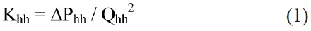
where ΔPhh is the header to header differential pressure across the reactor core and Qhh is the pass flow rate. Considering Equation (1), for single phase flow conditions, the flow resistance of the reactor core is practically unaffected by SG hydraulic changes. Therefore, a decrease in flow from a divider plate replacement will necessarily also decrease the header-to-header differential pressure across the core, and an increase in flow from SG cleaning will necessarily increase the header-to-header differential pressure, as observed in Fig. 3. It should be noted, as apparent in Fig. 3, divider plate leakage and magnetite redistribution effects appear to be about equal in magnitude but of opposite direction. SG aging, therefore, directly affects the header boundary conditions of the header-to-header differential pressure (Fig. 3) as well as the inlet header temperature (Fig. 2).
The aging behaviour of the below header geometry can, in part, be expressed in terms of the header-to-header differential pressure, as shown in Figs. 3 and 6. As the plant ages, magnetite build up along the feeders is expected to increase. Consequently, the header-to-header differential pressure is also expected to increase, as shown in Fig. 3 (upper curve). However, it is noted that PT diametral creep reduces the reactor core flow resistance, and consequently, as per Equation (1), also tends to reduce the header to header differential pressure, as shown in Figs. 3 and 6 as well.
4. PRESSURE TUBE DIAMETRAL CREEP EFFECTS
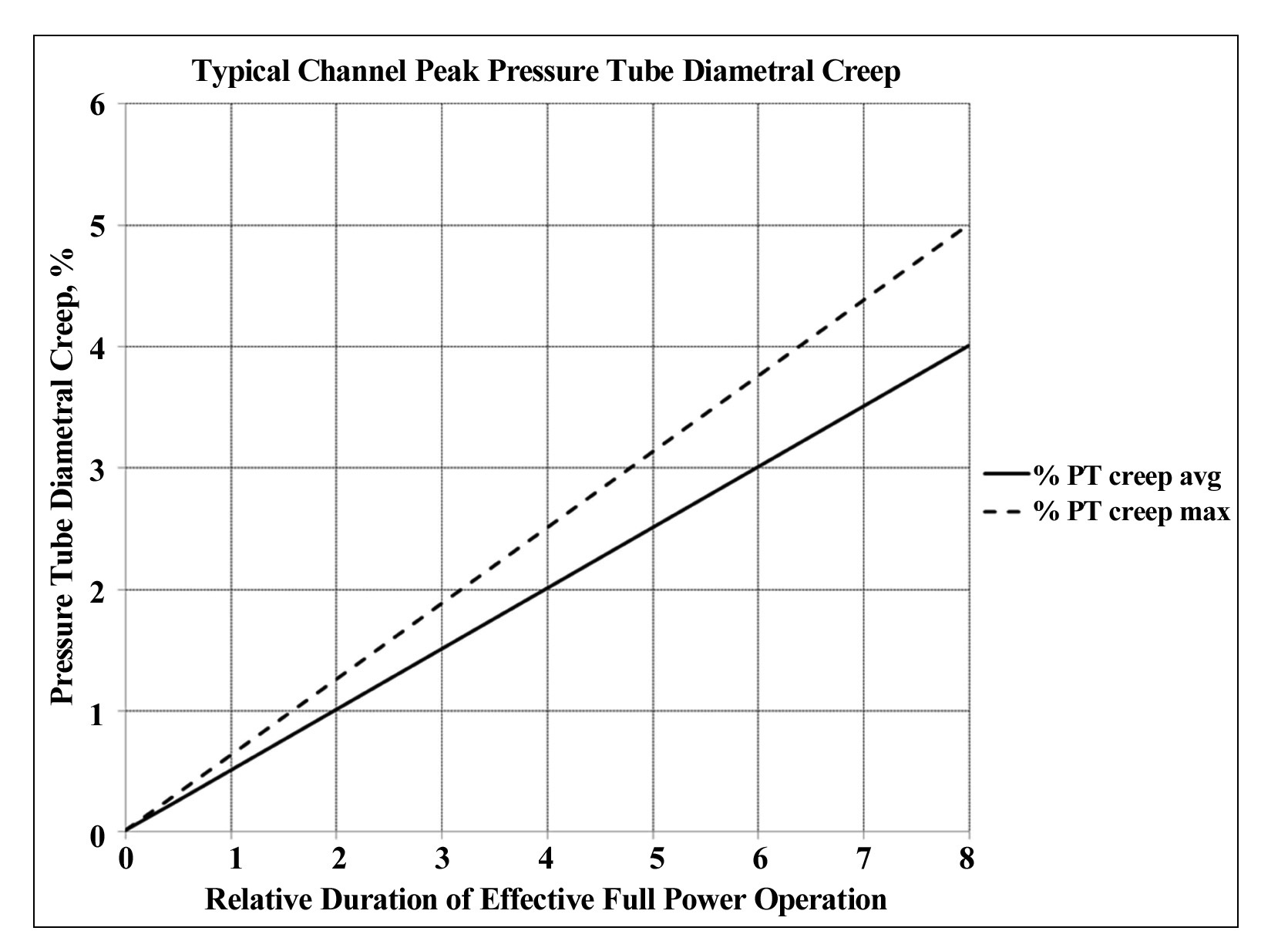
In an iterative process between the RC-1980 based code (References [8]) and a HTS analysis code, a bestestimate PT diametral creep profile of the pressure tube
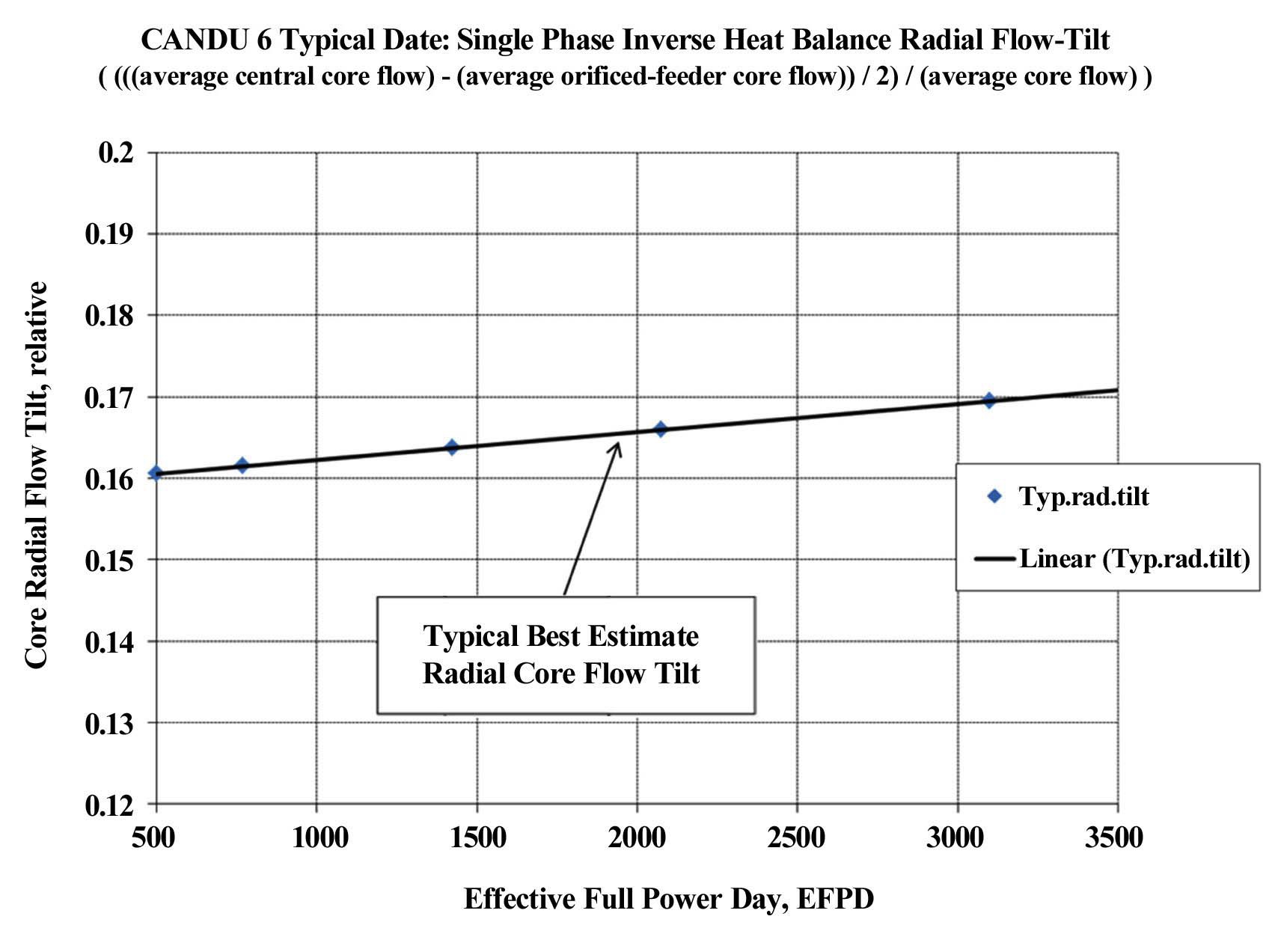
can be derived to reflect the aging of the pressure tubes (References [7]). An appropriate, minor normalization will then match the predictions to site-specific measurements yielding average as well as upper-limit pressure tube diametral creep, as shown in Fig. 8. For newer improved reactors pressure tube diametral creep is evident in a decreasing HTS core hydraulic resistance, as shown in Fig. 9. Since pressure tube diametral creep is the highest in the central core, where the fast neutron flux is the highest, the hydraulic resistance will be lower in the central channels, and an increasing radial flow tilt develops with age, as shown in Fig. 10. Therefore, in addition to the below header hydraulic resistance tracking the radial flow tilt tracking also becomes important (References [6]).
5. EFFECT OF HTS AGING ON THE CANDU SAFETY ANALYSIS
Aging of the primary heat transport system (PHTS) components of a CANDU reactor may cause some changes
to the thermal-hydraulic characteristics, and these changes can also affect the operational and safety margins of the CANDU reactor. The primary aging phenomena include pressure tube diametral creep, magnetite deposition, feeder orifice degradation, and a fouling effect of the steam generator as mentioned earlier.
A safety analysis methodology may involve statistical or deterministic tools. Statistical analysis based methodologies generally take advantage of the low probability that each uncertainty will affect the analysis outcome negatively, and are, therefore, generally considered the most true and realistic analyses. Such an analysis may have considerable complexity. A deterministic analysis, in contrast, may assume that all uncertainties will realize at most a negative outcome. An analysis based on this assumption will necessarily be conservatively bounding, in the sense that the associated scenario is necessarily unlikely.
An improvement in the safety analysis is achieved by not only improving the methodology but also by reducing the uncertainties associated with the aging characteristics of the reactor components. A reduction in uncertainties may be achieved by better knowledge of the aging characteristics of the reactor components in association with well-defined maintenance procedures allowing more accurate predictive capability of reactor performance. Further, uncertainties may be reduced by an appropriate aging tracking and adjustment procedure, as described in References [6] and [9]. This procedure places less emphasis on prediction and more emphasis on tracking reducing uncertainties and aging allowances. Improvements in the methodology and reduction of uncertainties may lead to less restrictive safety limits.
The aging behavior of the heat transport system (HTS) for an older CANDU 6 plant as well as newer, improved plants impacts the safety systems including the performance of channel flows and Critical Channel Power (CCP), which are major components in the Regional Overpower Protection (ROP) system. This safety system protects against slow Loss of Regulation (LOR) accidents. Here CCP is defined as the channel power at which the fuel elements experience intermittent dryout conditions (without fuel failure). The margin to CCP can be tracked over time, and appropriate corrective actions can be determined to ensure that adequate margins continue to exist throughout the life of the station. Reference [6] explores this application for a newer, improved plant. Safety analyses based on CCP evaluations are covered in detail in References [5], [6], and [7]. Therefore, this section of the paper explores a post-CCP safety analysis for aged reactors associated with a postulated feeder stagnation break.
A recent safety analysis for the refurbished Wolsong 1 reactor considered the aging effect of the reactor by assuming that the core is in the 11 EFPY (effective full power year) state. Here, 11 EFPY means that the core is assumed to be operated for 11 EFPY after the refurbishment of Wolsong 1. From the site operation data and thermal-hydraulic analysis results, the aging characteristics for the major components of the PHTS of the 11 EFPY aged core were derived including the roughness data of the feeder pipe, steam generator, end-fitting and pressure tube, creep data for pressure tube, orifice degradation, and steam generator fouling.
To consider the HTS aging effect on the CANDU safety analysis, this section shows the analysis approach for a fresh core and an 11 EFPY core derived from the Wolsong site operational data and used in the comparison of the safety analysis results for a fresh core and an 11 EFPY aged core in the case of a postulated feeder stagnation break.
5.1 Aging Data Derived from Site Operational Data
After the refurbishment of Wolsong 1, the pressure tube diametral creep becomes zero as the pressure tubes are being replaced. Therefore, no creep is considered at the post refurbishment zero EFPY plant model. With the installation of new feeders, the magnetite transport effect is also eliminated for feeders and pressure tubes. This state is called a “fresh core” after the refurbishment.
To make the “aged core” model, which is assumed to be operated 11 EFPY after the refurbishment, all aging factors have to be considered simultaneously. Using the linear interpolation between the reference model at zero EFPY pre-refurbishment and the already existing average tracked site data at 2000, i.e. 5270 EFPD, the desired 11 EFPY aging data can be created. It was recognized that not all reactor component aging trends are linear, depending on the material characteristics as well as the operational or maintenance preferences. Therefore, appropriate uncertainty and bias allowances have to be included in the aged model to ensure the applicability of the analysis. A periodic verification of the analysis assumption may also be required.
The roughness increases as the operation proceeds, but the orifice resistance generally degrades. The actual aged data are considered in the safety analysis to verify the aging effect on safety.
5.2 Comparison of Safety Analysis Results for the Fresh and Aged Core
To investigate the effect of component aging on safety, a safety evaluation assesses both the fresh and aged core states for a postulated feeder stagnation break accident. A break in an inlet feeder can lead to a reduction in coolant flow in the adjacent fuel channel with the channel remaining under power. Depending on the break size, a complete stagnation of the channel flow can occur, resulting in rapid fuel and channel heat-up and channel failure.
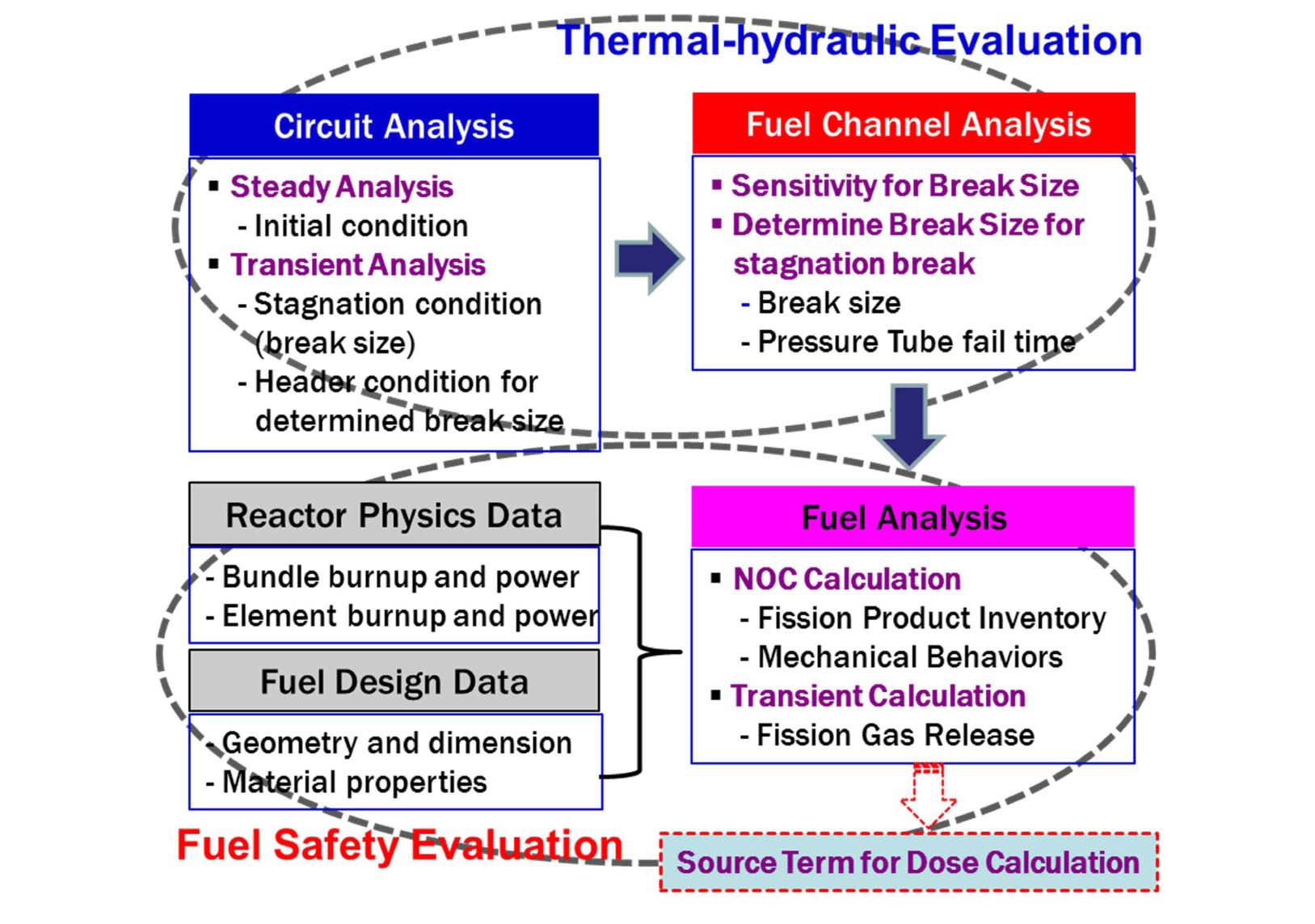
The safety analysis for the inlet feeder break is carried out through two steps, the first of which is a thermalhydraulic evaluation, and the other is a fuel safety analysis, as shown in Fig. 11.
5.2.1 Thermal-hydraulic Analysis
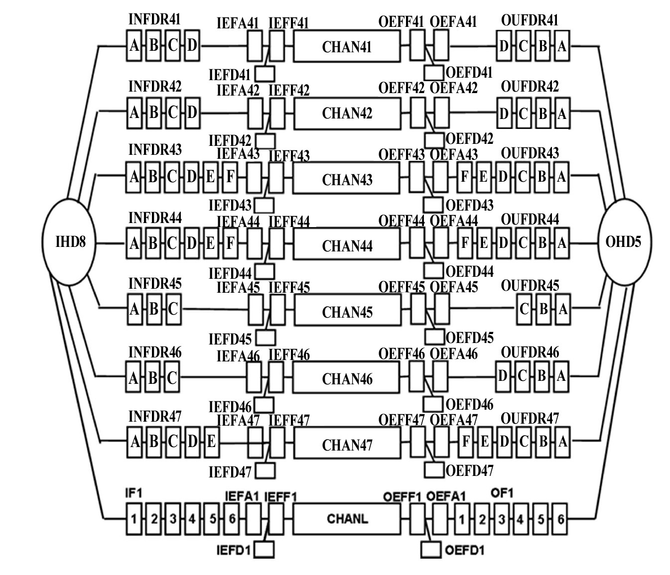
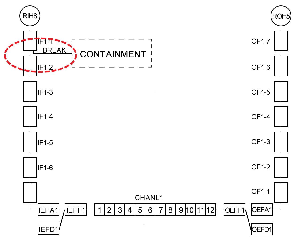
A thermal-hydraulic analysis was performed using the average channel circuit model with a specific broken channel for the CATHENA code [10]. The circuit model was used to determine the system response to a break size. The reactor inlet header conditions obtained from the circuit simulations were used as boundary conditions for analyzing the fuel and fuel channel behavior. Fig. 12 shows the circuit model of the broken pass for a circuit analysis. The broken pass, as shown in Fig. 12, is represented by 7 multiple average channels (94 averaged) in parallel with a single channel (the broken channel). The single channel analysis was performed to examine the channel thermal-hydraulic behavior. A single fuel channel model for the limiting channel, as shown in Fig. 13, covers a single channel from the inlet header to the outlet header only. Herein, the limiting channel has the same geometry as channel O6, but the channel power and bundle power of the two center bundles have been modified to the licensing limits of 7.3 MW and 935 kW, respectively. The transient header boundary conditions of the pressure, vapor enthalpy, liquid enthalpy, and void fraction generated from the circuit simulations are provided for a single channel analysis.
Stagnation feeder breaks result in channel failure owing to rapid fuel and channel heat up. The timing of channel failure and the channel conditions at this time are a strong function of the break size, a parametric survey for the break size is performed using the single fuel channel analysis for each aged and fresh cores.
5.2.2 Fuel Safety Analysis
The objective of the fuel analysis for a feeder break accident is to estimate the quantity and timing of the fission product release from the fuel in the affected channel. The amount and distribution of the fission products within the fuel element play a major role in determining possible radiation doses to the public after postulated accidents have occurred. When a fuel sheath fails, the gap inventory of fission products is released over a period of time as the fission gases within the fuel element migrate towards the defect site. The ELESTRES [11] code is used in the fuel
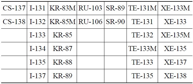
[Table 1.] Fission Product Isotopes

Fission Product Isotopes
analysis to evaluate the fission product inventory and fuel behavior under normal operating condition and provide the initial transient coolant conditions. Gehl’s model [12] is used to assess the amount of fission gas released from the fuel during the transient period.
The fission product inventory results for the fresh and aged cores for each isotope under normal operating conditions may be compared. The distribution of the fission product at the gap, grain boundary, and in-grain may differ because the diffusion rate of the fission product is dependent upon the fuel temperature. Although the total fission product inventories (gap + grain boundary + in grain) are the same for both aged and fresh cores, because the total inventory is proportional to the element power, gap, and grain boundary inventories, which are promptly released at the time of a fuel failure, for the aged core may be higher than those for the fresh core.
To evaluate the amount of released fission gas more conservatively, it may be assumed that all fuel sheaths in the broken channel are failed and the entire gap inventory is released instantaneously at the time of the accident. An additional fission gas release during the transient from the fuel grain and grain boundary is calculated by applying Gehl’s release model [12]. The amount of released fission gas is calculated until the time of fuel channel failure, which is determined from the fuel channel T/H analysis.
The results of a fission gas release for the fresh and aged cores following the feeder stagnation break may be compared. The number of considered fission gases is 30 including the isotopes of I, Kr and Xe, as shown in Table 1. The initial release of the aged core may be higher because of the prompt release of more gap inventory of the aged core. The released fission gas abruptly increases at the time of the channel failure. However, the final cumulative fission gas release for the aged core may be higher by about 10% when compared with the fresh core. The 11 EFPY aged core may therefore be more conservative than the fresh core from the fuel safety perspective.
6. DISCUSSIONS AND CONCLUSIONS
The aging of the primary heat transport system components of CANDU reactor may cause changes to the thermal-hydraulic characteristics and these changes also affect operational and safety margins of CANDU reactor. Thus, in this work, the aging phenomena and its effect on the thermal-hydraulic characteristics of CANDU 6 reactors was explored and subsequent safety analyses ranging from the assessment of safety limits associated with the prevention of intermittent fuel sheath dryout and fission gas release after fuel failure were summarized.
The followings are the main conclusions of this paper.
Known aging processes of the CANDU heat transport system, which would influence the Critical Channel Power (CCP) and post-CCP safety assessment are the increase of pressure tube diameter due to irradiation creep, increase of hydraulic resistance due to redistribution of iron oxides (magnetite), and erosion of the edges of flow-reducing orifices.
Improvement in safety analysis is achieved by improving the methodology and by reducing the uncertainties associated with the component aging characteristics. In order to reduce the uncertainties associated with the aging, an appropriate aging tracking and adjustment procedure is necessary, and this may lead to less restrictive safety limits.
Key measurable site parameters as a means of tracking the aging of the CANDU heat transport system (HTS) include temperature, pressure, coolant flow rate, and core flow distribution. Analysing those key parameters at different historical times will allow the determination of HTS component aging trends, and these trends can then in turn be used to predict the HTS operating conditions at future operating points.
A specific safety assessment for stagnation feeder breaks was carried out for both fresh and aged cores in order to verify the aging effect on the post-CCP safety analysis. From the comparison of the fission gas release results, the aged core, which considers the aging effect of HTS components, showed higher fission gas release about 10% compared to that of the fresh core. Thus, for a conservative safety assessment, which is a basic characteristic of the deterministic safety assessment, the HTS aging should be considered in the safety analysis. Therefore, better understanding of the component aging of CANDU reactor and more accurate tracking methodology and aged model development are necessary.