A practical Ship Inner Shell Optimization Method (SISOM), the purpose of which is to improve the safety of the seagoing transport ship by decreasing the maximum Still Water Bending Moment (SWBM) of the hull girder under all typical loading conditions, is presented in this paper. The objective of SISOM is to make the maximum SWBM minimum, and the section areas of the inner shell are taken as optimization variables. The main requirements of the ship performances, such as cargo hold capacity, propeller and rudder immersion, bridge visibility, damage stability and prevention of pollution etc., are taken as constraints. The penalty function method is used in SISOM to change the above nonlinear constraint problem into an unconstrained one, which is then solved by applying the steepest descent method. After optimization, the optimal section area distribution of the inner shell is obtained, and the shape of inner shell is adjusted according to the optimal section area. SISOM is applied to a product oil tanker and a bulk carrier, and the maximum SWBM of the two ships is significantly decreased by changing the shape of inner shell plate slightly. The two examples prove that SISOM is highly efficient and valuable to engineering practice.
SISOM Ship Inner Shell Optimization Method
SWBM Still Water Bending Moment
SWSF Still Water Sheer Force
CH Cargo Hold
WBT Water Ballast Tank
GA Genetic Algorithm
ISP Inner Shell Plate
LCV Longitudinal Center of Volume
MMLC Maximum bending Moment Loading condition
HTSP Hopper Tank Sloping Plate
TWSP Topside Wing tank Sloping Plate
The SWBM is a major component of the hull girder bending moment, and it is very important to the structural strength of transport ship. Large SWBM will cause several types of hull structure failures, such as fatigue crack, local buckling deformation, or even catastrophic incidents. According to the report provided by Shipping Statistics and Market Review, there were 661 ships, 51.4% of which are bulk carriers or oil tankers, are total loss because of founderings and weather during 1989 and 2005. In those total loss ships, the age of which are less than 10 years occupies only 11%, while most of the ships are built more than 15 years ago. From this data, it can come to a conclusion that most of these ships are not lost due to loss of stability or operation faults, but because of the weakening of global strength after years of structure corrosion. There are two ways to improve the safety of ship during its whole life cycle. One is to reinforce the hull structure maintenance, especially structure corrosion prevention. The other is to enhance the ability of ship to survival more extreme sea conditions at the design stage, such as increasing the plate thickness or decreasing SWBM, and the latter is more effective and economical than the former.
There are many researches on how to decrease the maximum SWBM of ship with optimum design in the previous literatures. Ivanov and Wang (2007) proposed an simplified Still Water Sheer Force (SWSF) and SWBM calculating method, which is used in ship tank subdivision with the bulkhead positions as variables; Chen et al. (2010) proposed a tank subdivision optimazation methods based on Genetic Algorithm (GA) to minimize SWBM under sequential ballast water exchange condition; Lin et al. (1994) put forward a neural network expert system, which is applied for the intelligent design of ship and optimum tank subdivision. These researches are effective for reducing the maximum SWBM, but still, they have the following shortages:
(1) The existing literatures are all aimed at the optimum design of the transverse bulkhead position, and they are able to decreasing the maximum SWBM in part loaded conditions such as ballast water exchange condition, heavy ballast condition, and heavy cargo alternate loading condition etc. However, they are invalid for the full load and normal ballast condition, in which SWBM has nothing to do with the transverse bulkhead position. For the ship the maximum SWBM of which appears in normal loading condition or full loading condition, the existing method could not reduce the maximum SWBM of the hull.
(2) In the existing methods, only one loading condition is considered in their optimization model, which will cause the performance of ship under some other loading conditions not satisfying the requirements. That means those methods could not ensure the feasibility of the optimum solution.
Generally, the seagoing oil tankers and bulk carriers have double bottom and double shell (or single shell but with hopper tank and topside wing tank, such as single shell bulk carrier). That is to say, the cargo hold segment of these ships consists of two layers. One is the outer shell including outer bottom and outer side shell. The other one includes the inner bottom plate, hopper tank sloping plate, double shell plate, topside tank sloping plate etc., and they are called Inner Shell Plate (ISP) for short. ISP is the boundary of Cargo Hold (CH) with Water Ballast Tank (WBT). In this paper, cargo hold and cargo oil tank are all called CH for convenience. As a result, the shape of ISP is a predominant influence on the weight distribution of both cargo/ cargo oil and water ballast under each loading condition. As the maximum SWBM is closely related to weight distribution, so it is an effective way to decrease the maximum SWBM by shape optimization of ISP. On this base, the Ship Inner Shell Optimization Method (SISOM), which is used to minimize the maximum SWBM of the seagoing transport ship under all typical loading conditions, is presented in this paper.
To make the optimum solution feasible, there are several requirements that should be always satisfied. For the transport ships, sufficient CH capacity is a basic functional requirement. Under ballast conditions, ship should have adequate aft draft to meet the requirement of propeller and rudder immersion. However, aft trim is not the lager the better, for large aft trim is unfavorable to bridge visibility. So the draft and trim should in an appropriate range, which requires that the ship should have not only sufficient WBT capacity, but also proper Longitudinal Center of Volume (LCV) for all WBTs. For the oil tanker, ISP should meet the requirement of permanent means of access as described in SOLAS (2004), and the minimum requirement of pollution prevention of MARPOL (2001) should also be satisfied. In addition, ISP should fulfill the request of construction technology. All the above requirements should be satisfied in ISP shape optimization.
The main object of this paper is to propose the objective model for SISOM, solve the optimization problem and apply the method in engineering practice. This paper is organized as follows: in section 2, the mathematical optimization model of SISOM is proposed and explained in detail; the solution of the optimization model is discussed in section 3; two applications of SISOM, one is the optimization design for a 26,000 DWT product oil tanker, and the other is for a 69,000 DWT bulk carrier, are introduced with the purpose of explaining how to use SISOM in engineering practice; section 5 is a brief conclusion of SISOM.
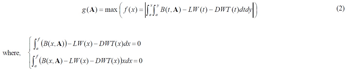
The purpose of SISOM is to decrease the maximum SWBM under all typical seagoing loading conditions via shape optimazation of ISP, on condition that all the safety and function requirements are satisfied. As to most of the seagoing oil tanker and bulk carrier, there is a loading condition, the maximum SWBM of which is significantly larger than that of the other loading conditions significantly. This loading condition is called Maximum bending Moment Loading Condition (MMLC) in this paper. For example, MMLC for 20,000-80,000 DWT oil tankers is ballast departure loading condition, and MMLC for 65,000-80,000 DWT bulk carriers is heavy cargo alternate loading condition etc. Even though the maximum SWBM of typical loading conditions could be changed via ISP or subdivision optimization, MMLC still has the largest maximum SWBM for those ships. As a result, reducing the maximum SWBM under MMLC is equivalent to reducing that of all typical loading conditions. So SISOM takes the absolute of maximum SWBM under MMLC as objective function.
For convenience of design and construction, all ISP should be planar. Along ship length direction, ISP should have several corner positions, where at least one plate of ISP has a corner. Those positions are called Corner Positions for short in this paper. Assume that the bulkhead position and the corner positions of ISP keep unchanged, then the capacity distribution of CHs as well as WBTs is determined by the section areas of ISP at corner positions, and so is the maximum SWBM of MMLC. SISOM take the section areas of ISP at corner positions as variables, and create the optimization model for SISOM as follows:
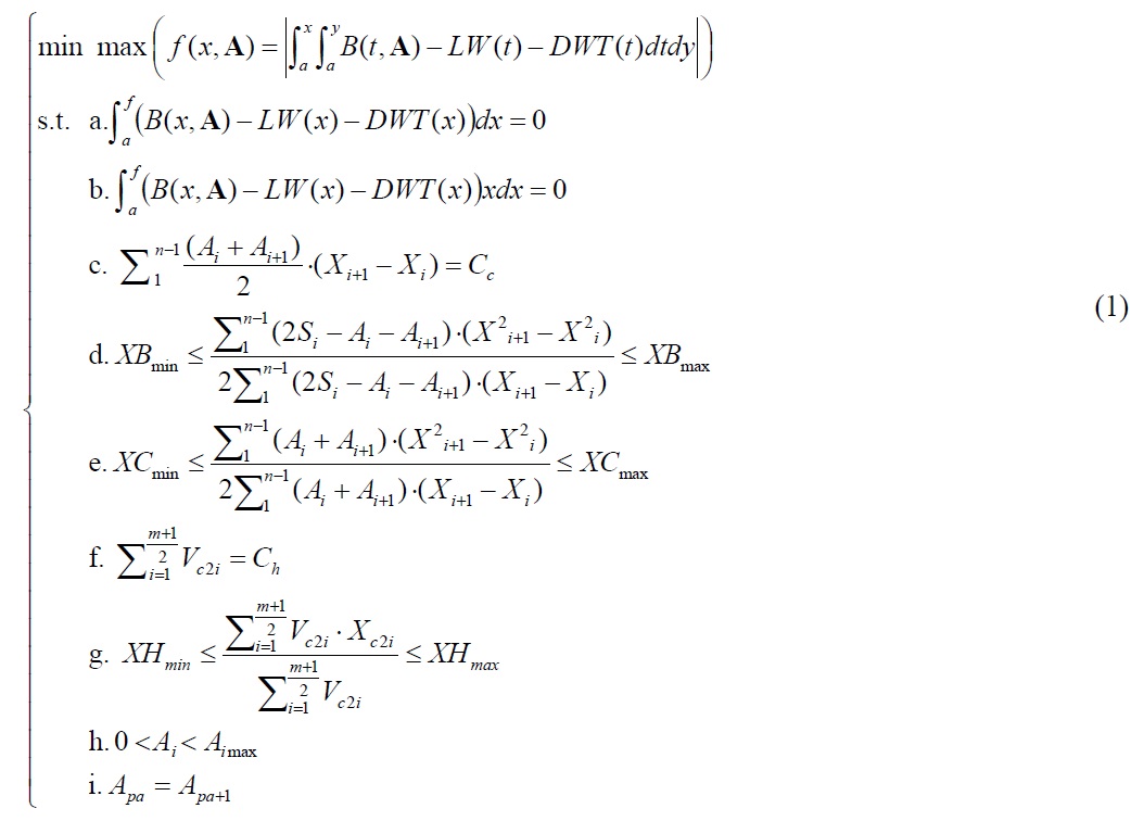
where
In the objective function,
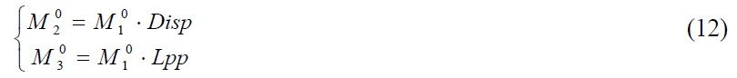
(1) Gravity-buoyancy balance of the hull.
(2) Moment of gravity-buoyancy balance of the ship.
(3) The total volume of CHs keeps unchanged. As the hull surface as well as bulkhead position is specified in SISOM, the total volume of all CHs and WBTs is fixed. So this constraint also means the total volume of WBTs keeps unchanged too.
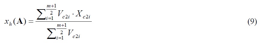
(4) If deadweight is specified under a loading condition, the draft and trim of ship is mainly determined by LCV of the cargo or ballast water. For normal ballast loading condition, the LCV of WBTs should not be greater than XBmax to guarantee propeller and rudder immersion, and it should not be smaller than XBmin to avoid wave slap on the fore end of hull, or to avoid influence of bridge visibility.
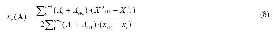
(5) Being similar with the normal ballast loading condition, LCV of all CHs should be smaller than the upper limit XCmax, and greater than the lower limit XCmin.
(6) If the ship has heavy cargo alternate loading condition, the total volume of the heavy CHs should keeps constant. This constraint is invalid if no such loading condition exists for the ship.
(7) If the ship has heavy cargo alternate loading condition, the LCV of all heavy CHs should be within the range of [XHmin, XHmax] to get proper floating condition. This constraint is invalid if no such loading condition exists.
(8) ISP should meet the minimum requirements of pollution prevention and damage stability, which means the distance between each plate in ISP with the hull surface, should not be smaller than its lower limit. And because the hull surface is not changed, the section area of ISP at the ith corner position, Ai , has upper limit Aimax, that is Ai≤Aimax (1≤i≤n). Obviously, Ai should be greater than zero.
(9) The section area at the aft end and fore end of parallel middle body is Apa and Apa+1 respectively. Apa and Apa+1 are set to be equal. This constraint ensures that the transverse section of ISP keeps unchanged in the range of parallel middle body.
There are more requirements that must be satisfied than that stated above, such as intact stability, damage stability, service speed, seakeeping etc. Nevertheless, SISOM assumes that only the shape of ISP could be modified slightly, while all the other part of the design scheme, such as principal dimensions, structure that is uncorrelated to ISP, and hull surface etc, remain unchanged after optimization. As a result, SISOM will not affect the above performances remarkably, which means it is not necessary to take those requirements into account in the optimization process. After taken those factors into count, the optimization becomes a multi variable, multi nonlinear constraints, and nonlinear optimization problem. The next task is how to solve the optimization model.
SOLUTION OF THE OPTIMIZATION MODEL
SISOM has a complex objective function, and the non-linear constraints greatly increase the complexity of the optimization model. It could not be proved that SISOM has the unique optimum solution. On the contrary, there may be quite a lot of exreme values for the optimization model. As to most of the transport ship, ISP before optimization is a satisfactory solution consiering all design factors, and the less modification of ISP, the more beneficial to the productivity in design and production stage. As a result, the global optimum solution is the most important one mathematically, but the local optimum one that closest to the oriinal ISP is of great importance to engineering.
Theoretically, the evolutionary algorithms could get the global optimum solution for the multi-extreme value optimization problem. In the subdivision optimization or structure optimization methods for ship, the population-based methods are widely used in the existing literature, such as genetic algorithm (Chen et al., 2010; Olcer et al., 2006; Papanikolaou et al., 2010; Vasoncellos, 2010; Turkmen and Turan, 2007), and particle swarm optimization (Cui and Turan, 2010) etc. However, for the problem that has numerous extreme values, SISOM for example, it is very difficult for the population-based methods to avoid the premature convergence problem. GA has been used to solve optimization model (1) in this study initially, but it proved to be low in rate and the optimum solutions are closely related to the random initial populations. So in this paper, the gradient-based algorithm is used to solve optimization model (1). Although gradient-based algorithm could not necessarily converge to the gloal optimum solution, it converges to the one that closed to the original ISP, and it is also very valuable to engineering practice.
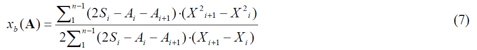
In optimization model (1), constraint a and constraint b is associated to buoyancy function
The above modification simplifies the constraints, but makes the objective function more complex. However, it is not very important, for the complex objective function could be calculated through programming. After this modification, all the constraints could be expressed by algebraic expression with the variables. Then by means of penalty function method, optimization model (1) is converted into an unconstrained problem,

The meaning of the functions in Eq. (3) is as follows:
(1) C(A) is the penalty item for CH volume, and it is used to make the optimum solution satisfy the capacity requirements of CHs and heavy CHs,

where coefficient
(2) L(A) is the penalty item for LCV, and it is used to ensure that LCV for WBTs, CHs, and heavy CHs all satisfies the requirement. L(A) is defined as:
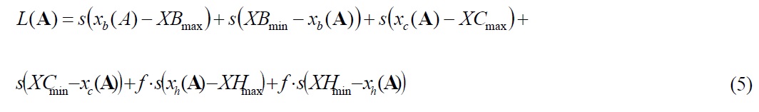
where coefficient
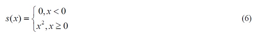
(3) R(A) is the penalty item for variables’ upper limit, and it is used to ensure that the section area of ISP at each corner position does not exceed the maximum one calculated according to pollution prevention and damage stability requirements. R(A) is defined as follows:

In Eq. (3),

where
where
Suppose
exist and continuous approximately. So it can be proved that
exist and continuous, where

where ▽

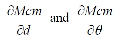
where the partial derivative of

▽

where A

where
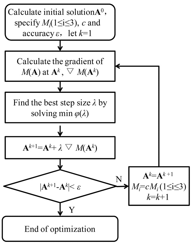
The solving process of SISOM is shown in Fig. 1. In the iteration process, if any of the constraint is not satisfied, the penalty function will increase the objective function. The three penalty coefficient increases along with the iteration time, which makes the solution feasible gradually. When all the requirements are satisfied, all the penalty items become zero, and then the optimazation direction is toward the one that makes the maximum SWBM minimum.
In this optimization model, coefficient
APPLICATION OF SISOM IN ENGINEERING PRACTICE
>
ISP shape optimization design for the 26,000 DWT product oil tanker
SISOM is applicable for most of the seagoing oil tanker and bulk carrier. Firstly, take a 26,000 DWT product oil tanker as example to discuss the application of SISOM in double shell oil tankers. The principal dimensions of the oil tanker are shown in Table 1.
[Table 1] Principal dimensions of the 26,000 DWT product oil tanker.

Principal dimensions of the 26,000 DWT product oil tanker.
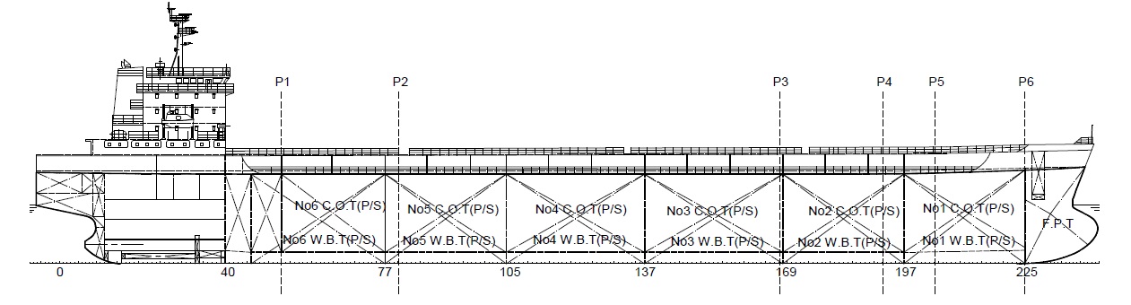
This oil tanker has six pairs of cargo oil tanks. Among all seagoing conditions, normal ballast departure condition has the maximum SWBM, as shown in Table 2. Therefore, the normal ballast departure condition is MMLC for this oil tanker. There are six corners, which are marked as P1 to P6 in Fig. 2, and the section area of ISP at each corner position is taken as variables.
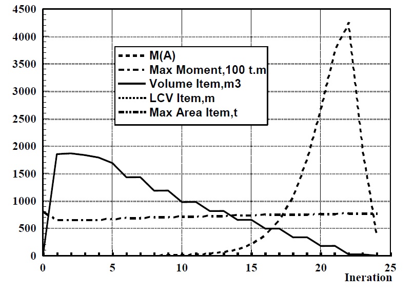
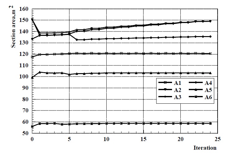
The optimization converges after 24 iterations. The variables in each iteration step is shown in Fig. 3, which indicates that all variables change greatly in the first iteration, and return to the vicinity of the initial solution gradually in the following steps.
[Table 2] The maximum SWBM of typical loading conditions for 26,000 DWT product oil tanker.

The maximum SWBM of typical loading conditions for 26,000 DWT product oil tanker.
The objective function
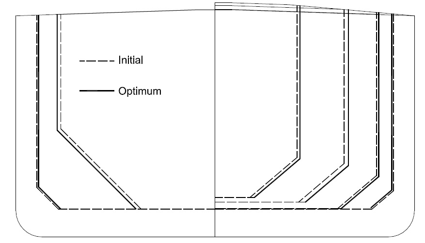
Adjust ISP of the tanker according to its optimum section area. For this ship, ISP consists of three plates, which are the inner bottom, hopper tank sloping plate and double shell plate. Assume that double bottom height is the same as the initial ISP, double shell plate is perpendicular to base plane, and the angle of hopper tank sloping plate in the transverse section keeps unchanged. Besides, suppose that area variation of each section distributes equally in order to minimize the influence on the structure. Under these assumed conditions, the optimized ISP is created and shown in Fig. 5 compared with the initial one.
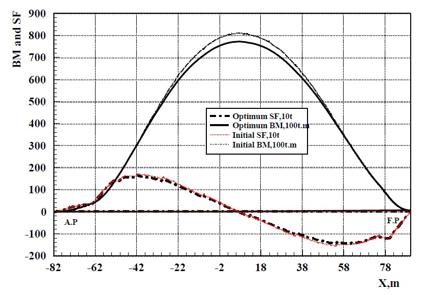
The SWSF and SWBM curve before and after optimization is shown in Fig. 6. The maximum SWBM of the ship before optimum design is 81,028
>
ISP shape optimization design for the 69,000 DWT bulk carrier
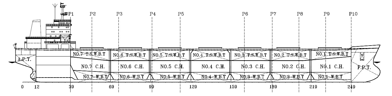
In this section, a 69,000 DWT single hull bulk carrier is taken as example to indicate the application of SISOM in seagoing bulk carriers. The subdivision drawing of the bulk carrier is shown in Fig. 7, and the principal dimensions of this ship are shown in Table 3.
[Table 3] Principal dimensions for the 69,000 DWT bulk carrier.

Principal dimensions for the 69,000 DWT bulk carrier.
This bulk carrier has 7 CHs and 17 pairs of water WBTs in CH segment. ISP has 10 corners as shown in Fig. 7, and the section areas of ISP at these 10 corner positions are taken as variables. The maximum SWBM of typical loading conditions of this ship is shown in Table 4.
[Table 4] The maximum SWBM of typical loading conditions for the 69,000 DWT bulk carrier.

The maximum SWBM of typical loading conditions for the 69,000 DWT bulk carrier.
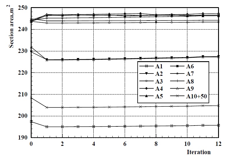
The loading condition with maximum SWBM is the heavy cargo alternate loading condition for this bulk carrier, and this loading condition is made MMLC. The variation curves for each variable are shown in Fig. 8. The optimization complete after 12 iterations.
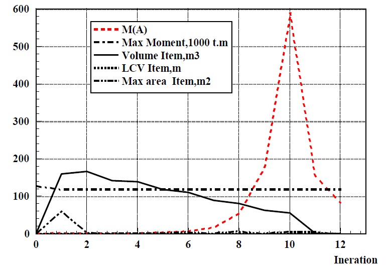
The variation curves for objective function
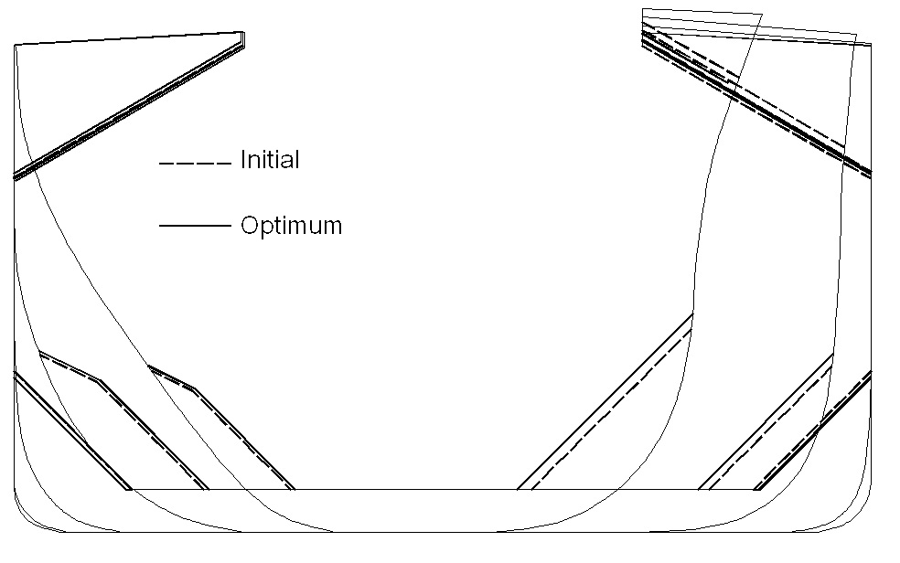
This ship is a single hull bulk carrier, so the variation for the transverse section area of ISP consists of two parts, the hopper tank variation and the topside wing tank variation. Suppose that the double bottom height is not to be changed, and then the variation of hopper tank is caused by offsetting of the Hopper Tank Sloping Plate (HTSP) along the normal of itself, and the variation of topside wing tank by that of the Topside Wing tank Sloping Plate (TWSP). In order to avoid influencing the structure too much, ISP variation is made uniform distribution in HTSP and TWSP. For ISP section corresponding to the
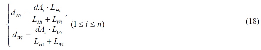
where
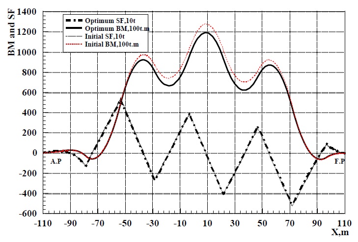
The SWSF and SWBM curves before and after optimization for this bulk carrier is shown in Fig. 11. For the initial design scheme, the maximum SWBM is 128,160
>
Optimization result analysis
In the first application, SISOM reduced the maximum SWBM of the oil tanker by 5%. For this oil tanker, SWBM occupies 42% of the total bending moment. So SISOM is able to decrease the maximum bending stress by 2%, which will greatly reduce the risk of structural yield and buckling failure under extreme sea conditions, and this is especially important to the ship that has been used more than 10 years. For most of the transport ship, the hull should undergo the full loaded and ballast condition in sequence, and hull girder bears large sagging and hogging moment alternatively. This is an important cause of structure fatigue failure. SISOM is able to decrease the maximum SWBM of hull, which is equivalent to reduce the amplitude of the alternating load. So SISOM is an efficient way to improve the hull structure fatigue strength. The application to the bulk carrier has the similar conclusion with the oil tanker. Moreover, SISOM is also an effective method for ship optimization design. As SISOM is able to reduce the requirement of hull section modulus according to the rules such as JTP (2006) and JBP (2006), the thickness of some longitudinal plates could be reduced according to the optimum solution, and the deadweight of the ship is increased as a result. For example, according to the optimization result of the 69,000 DWT bulk carrier, the deck plate could be reduced by 1.5
In this paper, a new method named SISOM is proposed to improve the safety of seagoing transport ship via decreasing the maximum SWBM under all typical loading conditions. Being different from the existing methods, SISOM decreases the maximum SWBM by a novel way. The shape of ISP is taken as optimization object in SISOM, and the maximum SWBM of ship could be decreased effectively by optimizing the shape of ISP slightly. In order to ensure the optimized solution feasible, the main performance parameters of ship, which may be changed in the optimization process, are taken as constraints in the optimization model, and the optimum solution satisfies the following design requirements:
(1) Loading capacity requirement.
(2) Propeller and rudder immersion requirement.
(3) Minimum requirement of the fore end wave slap.
(4) Bridge visibility requirement.
(5) Floatation under typical loading conditions.
(6) Minimum requirement of pollution prevention and damage stability.
(7) Requirement of design and construction productivity, such as all plates in ISP are planer, transverse sections in the range of parallel middle body are the same.
SISOM is suitable for seagoing transport ship such as oil tanker and bulk carrier. The two applications presented in this paper prove that SISOM has good convergence and high efficiency. SISOM could effectively decrease the maximum SWBM by modifying ISP shape slightly, on promise that the optimum solution meet the requirements of main performances of ship, and that productivity in design and construction stage will not be affected too much. In conclusion, SISOM is a practical engineering approach with high efficiency, by which the safety of the seagoing transport ship could be improved effectively.