The principal purpose of this paper is to present a novel two phases rational scenario applied in constructing an offshore monopod platform; in which the two phases are the all-ground horizontal construction phase and the post-construction phase. Concerning the all-ground construction phase, a brief investigation of its different stages, i.e., pre-fabrication, fabrication, pre-assembling, positioning, assembling, and surface finishing is introduced. The important practical aspects of such construction phase are investigated without going into the nitty-gritty of the details involved therein. Concerning the post-construction phase, a clear investigation of its sequential stages, i.e., lifting, moving and up-righting is introduced. A finite element model (FEM) of the monopod platform is created to perform the structural analysis necessary to decide the suspension points/devices and the handling scenario during the various stages of the post-construction phase on a rational wise. Such structural analysis is performed within the framework of the three dimensional quasi-static modeling and analysis aiming at simulating the realistic handling condition, and hence introducing a reliable physical interpretation of the numerical results. For the whole effort to be demonstrated efficiently, the results obtained are analyzed, the conclusions are presented, and few related recommendations are suggested.
A Surface area of the structure component; A = 1742.7 m2, 0.332813 m2 and 39.7867 m2 for monopod, pad-eye and trunnion respectively
m Number of analysis/mesh elements; m = 363548, 1802 and 8119 for monopod, pad-eye and trunnion respectively
M Mass of the structure component; M = 165.151×10³ kg, 5.4319 kg and 7.420×10³ kg for monopod, pad-eye and trunnion respectively
n Number of analysis/mesh nodes; n = 732382, 3285 and 16493 for monopod, pad-eye and trunnion respectively
O Origin of all measurements, positioned at the intersection of the monopod centerline and the free surface level
V Volume of the structure component; V = 21.0116 m3, 5.4319×10⁻³ m3 and 0.952827 m3 for monopod, pad-eye and trunnion respectively
XG Coordinate of the center of gravity of the structure component, measured from O in X direction; XG = -1.15809× 10⁻³ m, 0.0 m and 0.0 m for monopod, pad-eye and trunnion respectively
YG Coordinate of the center of gravity of the structure component, measured from O in Y direction; YG = -1.08645× 10⁻³ m, 0.12537 m and 1.24997 × 10⁻² m for monopod, pad-eye and trunnion respectively
ZG Coordinate of the center of gravity of the structure component, measured from O in the Z direction; ZG = -12.8439 m, 3×10⁻² m and 1.50 m for monopod, pad-eye and trunnion respectively
α Up-righting angle of the monopod; α =0.0° “Horizontal”, 30.0°, 60.0° and 90.0° “Vertical”
δ Resultant displacement generated in monopod, pad-eye or trunnion in mm
δ1 Displacement generated in +I direction for monopod, pad-eye or trunnion in mm; I refers to X, Y or Z
σith ith principal stress calculated in monopod, pad-eye or trunnion in MPa; i may assume 1 or 3
σa Allowable normal stress of the steel grade used in fabricating the monopod, pad-eye or trunnion in MPa
σIJ Normal stress points along the +J direction and acts on the plane perpendicular to +I axis for monopod, padeye or trunnion in MPa; I and J refer to all combinations of X, Y and Z
σVM Von Misses equivalent stress calculated in monopod, pad-eye or trunnion in MPa
σy Yield strength of the steel grade used in fabricating the monopod, pad-eye or trunnion in MPa
τa Allowable shear stress of the steel grade used in fabricating the monopod, pad-eye or trunnion in MPa
max Maximum value of the stress or displacement in monopod, pad-eye or trunnion
min Minimum value of the stress or displacement in monopod, pad-eye or trunnion
b Bending stress in monopod, pad-eye or trunnion
t Tensile stress in monopod, pad-eye or trunnion
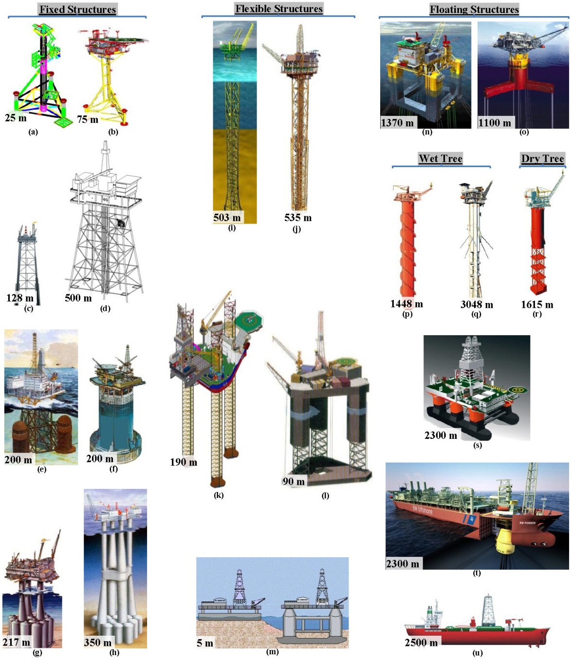
Offshore structures may be classified according to a variety of criteria, e.g., equipment carried, mobility, installation method, support method, etc. Fig. 1 classifies offshore structures, according to their hydrodynamic-structure interaction, into three principal categories; fixed, flexible and floating structures. The maximum recorded water depth, in which the various structures are installed, is written at the lower left corner of their images. Irrespective of their categories, offshore oil rigs and platforms are made of various steel grades ranging from mild steel to high-strength steel, reinforced concrete, or a combination of both.
Fixed offshore platforms are typically welded space frame structures made of tubular steel members with their legs and braces function to transmit the harsh environmental and topside loads into the seabed through a well-designed piles. The piles are driven into the seafloor through pile guides “sleeves” on the outer members of the platform. Offshore platforms may have one, three, four, six or eight caisson type legs. Platforms with a single caisson type leg are known as monopods; whereas those with three legs are known as tripods and so on (Chakrabarti, 2005). The detailed structural design of the platform frame varies widely from design to another and depends principally on the strength and fatigue requirements during the different processes of the post-construction phase.
The layout and design of the topside facilities may vary slightly depending on the platform mission “exploration, mining or extraction”, platform product “oil or gas”, and platform controlling system “manned or unmanned”. Manned topside facilities surely requires accommodation quarters, special transportation, as well as landing and evacuation facilities for personnel onboard, on the price of added safety requirements. The accommodation and habitability services are designed to cater the living needs of the personnel employed in the platform operation and maintenance. Also, the topside facilities include drilling equipment, hydrocarbon processing equipment, power generation unit, helideck and revolving crane (Gerwick, 2007).
Drilling and production pipes are brought up to the topside through conductor guides within the platform frame. The crude oil and gas travel from the reservoir through the production riser to the topside for treatment in the hydrocarbon processing equipment. The latter is designed to separate the extracted gaseous hydrocarbons “natural gas” from the liquid hydrocarbons “petroleum/rock/mineral oil”, and hence direct each hydrocarbon form into its correct processing branch for producing fuels and other associating derivatives, e. g., plastics, paraffin, waxes, solvents and oils. The produced fluid is then pumped to shore through the export pipelines (Randall, 1997; Mather, 2000; Bai and Bai, 2010).
The helideck may be positioned directly at the roof of the platform personnel accommodations or may be positioned at an elevated level above them. The configuration of the helideck is based on its intended use and the type of helicopters that may use it for their departure and arrival. The principal dimensions of the helideck should exceed the helicopter’s rotor diameter for proper ground cushion effect (GCE). The helideck is situated as far as physically possible from the potentially dangerous hydrocarbon processing area. For the details and recommended practice concerning all compulsory safety requirements of the personnel and the helicopter, the interested researcher may refer to American Bureau of Shipping (ABS, 2008).
The revolving platform crane is usually located on the top deck over the boat landing area. It is recommended that an open laydown storage area be located near the crane on each deck level as discussed in the American Petroleum Institute (API-Spec- 2C, 2010; API-RP-2D, 2007). Loading porches should be provided on the lower deck for easier access. Hatches may be required through the main deck to access equipment on the lower levels. Localized hoists or monorails may be needed in the area not accessible with the platform crane. Beside its conventional use in manipulating the materials and supplies between the platform and supply boats, the crane is also used in handling the platform equipment during their routine maintenance.
Although, offshore oil and gas exploration and extraction platforms were around for a longtime, such structures have seen phenomenal growth in number, geometry, equipment and size over the last three decades only. The fabrication challenges facing the construction of such platforms may be reverted to the satisfaction of certain levels of personnel safety, fabrication quality and cost, facilities and equipment operability, and pre-planned load-out schedule. As a matter of the limited relevant literature, an overview of few selected literatures over the last two decades is introduced hereafter.
Herbich and Bretschneider (1992) covered the design of port, harbors, navigation channels and estuaries; including planning and design, marine terminal technology, dredged navigation channels, hydraulic dredging technology, shallow-water dredging, dredged material disposal, anchors, coastal and oceanic buoy systems, marine processes, and wave-induced oscillations in bays, harbors and lakes. Also, valuable insights into the environmental effects of coastal engineering projects including the effects of dredging, spreading of oil by wind, current and waves, and response to oil spills were presented.
Al-Sharief (1995) briefly described the design considerations of an offshore platform as practiced by Saudi Aramco Co. together with the terminologies used therein. The methods used in calculating the design loads, fabrication and assembly procedures were highlighted. The quality control applicability at the fabrication yard was briefly explained. Also, the load-out, transportation and installation procedures of a fixed offshore platform installed in the Arabian Gulf were described.
Chakrabarti (2005) provided an invaluable encyclopedia concerning the state-of-the-art in various design concepts, structural design, model testing, installation, operation, maintenance, materials, control and safety requirements, and many other aspects pertaining to the vital field of offshore exploration and production systems. The practical aspects with handy design guides, and simple descriptions of the various detailed components of the offshore engineering and their functions were emphasized. Also, design-oriented engineering guidelines followed by their practical applications were provided to help in developing the design methodology of offshore structures.
Gerwick (2007) furnished the state-of-the-art practice in the design, construction, installation, maintenance, removal and salvage of marine and offshore structures, emphasizing their physical environmental aspects, construction relationships and sequences, and design-construction interaction. Also, a clear overview of the geotechnical aspects of the diverse marine soils, ecological and societal impacts of marine construction, materials and fabrication of offshore structures, and marine and offshore construction equipment were provided.
Sadeghi (2007) introduced an overview of design, analysis, construction and installation of offshore petroleum platforms suitable for Cyprus fields. The influence of many design aspects, e.g., right selection of equipment, platform type, drilling method, right planning, design, fabrication, transportation, installation and commissioning of petroleum platforms, water depth, and environment conditions on the field investment were broadly discussed. Also, various types of offshore platforms suiting the different sea-water depths of Cyprus fields were proposed.
Bureau of Ocean Energy Management, Regulation and Enforcement (BOEMRE, 2012) performed a comprehensive stateof- the-art qualitative comparison of the existing American Petroleum Institute (API), International Organization for Standardization (ISO) and Norwegian Offshore Standards (NORSOK). The state-of-the-art identified differences and recommendations for their possible resolution for application in the US Gulf of Mexico and the US West Coast. Two case studies were considered, one fixed platform and one Seagoing Platform for Acoustic Research (SPAR), and both suiting the Gulf of Mexico conditions. The resulting safety levels of the codes, which are functions of met-ocean data, load recipes, strength formulations, safety factors, etc., was quantified. However, the quantification of such safety levels for structural configurations other than those of the studied objects is necessary.
Gardner (2012) introduced the latest scientific and engineering developments in the field of tubular steel structures. Various keys and emerging subjects concerning the hollow structural sections such as special applications and case studies, static and fatigue behavior of connections/joints, earthquakes and dynamic response, and fire resistance were covered. Also, specifications and standard developments, material properties and section forming, stainless steel and aluminum structures, concrete-filled and composite tubular members, offshore structures, and castings and fabrication innovations were presented.
El-Reedy (2012) provided a practical guide for conventional and advanced techniques applicable to designing, construction, installation, inspection, repairing, strengthening, maintaining, and rehabilitation of fixed offshore platforms suiting all operational environments and conditions. The selection of the appropriate offshore structure was discussed from a techno-economic point of view, considering all factors, parameters and constraints that control the resultant design alternatives at each design stage. The design procedures for the fixed offshore structures, with comprehensive focus on the most important critical issues, together with the appropriate optimization techniques were presented. The structural design of piles and tubular joints, including the effect of fatigue loading, were presented theoretically and practically. Advanced qualitative and quantitative risk-based inspection techniques and maintenance planning were practically covered. Advanced repair method for scour, marine growth and deteriorating structural members were discussed.
Reddy and Swamidas (2013) examined the engineering ideas and offshore drilling platforms used for oil and gas exploration and production. A clear demonstration of both the theory and application of the relevant procedures of structure, fluid, and geotechnical mechanics to offshore structures was presented. A global description of the environmental forces that include those due to wave, wind, current, tides, earthquakes, ice floe/sheet action, and limit ice-load on Arctic structures was offered. The emphasized analytical principles comprehend the various issues that need to be considered in the analysis and design of an offshore structure. A detailed overview of the various structures used in the offshore environment and the preliminary costing factors that influence the site choice was highlighted. The various factors that influence the material choice for offshore structures including fatigue and corrosion of the platforms in the ocean environment were outlined.
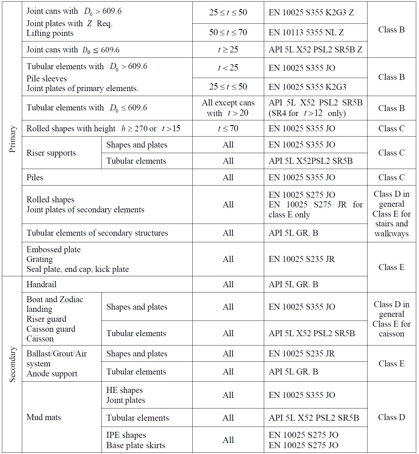
The principal material used in fabricating the considered monopod is the steel, which usually used in fabricating the conventional fixed offshore structures. Steel performs well in a harsh environment, subject to the combined actions of corrosive and erosive condition, and the dynamic cyclic and impact loads over a wide range of temperatures. Such harsh environment tends to initiate and propagate severe cracks which surely grow up into serious pre-and-post installation problems in the existence of improper fabrication details and procedures. Therefore, special care is considered in measuring and maintaining the spatial dimensions of the platform, controlling the out-of-roundness and diameter tolerances of the tubular members, and length tolerances of the pipes. In the pre-to-post fabrication phases, the environment-induced thermal strains may cause significant temporal distortions of the steel used, which imposes special criteria, requirements and arrangements on the steel quality and its control.
Steel is characterized by minimum yield strength, minimum ultimate strength, minimum elongation at rupture, notch toughness at low temperatures, through-thickness properties, weld-ability, fatigue endurance, chemical composition, etc. APISpec- 2B (2007), the American Institute of Steel Construction (AISC 360-10, 2010), and the American Society for Testing and Materials (ASTM A131/A131M-08, 2010; ASTM A992/A992M-11, 2010) have individually prepared standardized technical documents classifying steel plates, profiles, and pipes associated with their usage limitations, physical and mechanical properties. Table 1 records the physical and mechanical properties of the steel used in manufacturing the monopod according to the standard requirements of the AISC and ASTM. In fabricating the monopod, high strength steel
Welding materials are equally critical in assuring proper strength and ductility in service, and consequently they should be compatible with the base material as regards heat treatment and corrosion. In selecting the welding consumables, crack-opening displacement tests or other fracture mechanics tests are normally to be conducted. High-strength bolts and nuts, when used as structural elements, should have Charpy V-notch toughness values as that required for the structural steel members being connected (Finch, 2007; Jeffus, 2011).
[Table 1] Mechanical and physical properties of the steel used in constructing the monopod.

Mechanical and physical properties of the steel used in constructing the monopod.
>
Conventional vertical scenario
The manufacturing procedures of a fixed steel platform are usually decided according to its weight, its dimensions and the available yard facilities (Graff, 1981; Ford, 1987; Hordyk, 1988; Harrison et al., 1988). Conventionally, manufacturing of the small and medium sized fixed steel platforms is done vertically on the price of much time, effort, risk, and highly leveled cautions. The added cost of such vertical manufacturing scenario is surely reverting to the inherent necessity of working on highly elevated scaffolds with the consequent increased cost and risk latitudes. The estimated fabrication duration of a monopod platform using the vertical scenario may last from 6 to 12 months depending on the complexity and size of its structure.
>
Unconventional horizontal scenario
Away from the conventional vertical manufacturing scenario of a platform, whether it is performed in a yard or on-site, a novel double phase rational scenario for all-ground horizontal construction of a platform is proposed as depicted in Fig. 2. Such scenario is applied in manufacturing a monopod platform and proved its reliability and sustainability. All stages of the pre-topost construction phases, including those of the transient preparation phase, are performed in the PETROJET fabrication yard. The preparation phase affects the choice of the fabrication yard, cost and schedule of the overall project, and influenced by the shape and weight of the offshore platform. The whole scenario of the all-ground horizontal construction of the monopod consumes almost two months till load-out onboard the barge. The on-site installation includes launching and upending the platform, driving pilings, and welding such components into a single unit.
In PETROJET yard, the highest safety standard is used, especially for the personnel employed. Wireless radio is used in the indoor communications. Tools and supplies are prepackaged and hoisted up as units. Power cables are laid out to avoid the undesirable interferences between different operations and to minimize chances for snagging.
Indoor preparation stage
PETROJET fabrication yard was well established and were originally sited in a suitable geographical location for building small-sized service ships, small and medium offshore platforms and other strategic structures according to a pre-planned and well-organized reliable fabrication scenario. The latter is satisfied through a uniform workload, a short building cycle, an emphasized construction economics, a regular production flow of materials from a process to another, and eliminated manufacturing crosses. Of course, there are different interdisciplinary factors influencing a regular production flow, e.g. size and type of the marine structure, material handling equipment, fabrication processes, etc. It is an advantageous to arrange for manufacturing a structure with a piecemeal yard modification to avoid hindering the other production activities and allow for the yard peculiarities.
In PETROJET drawing office, the conventional mold loft is reduced to a virtual electronic mold loft in which a computeraided design system is used to provide all the necessary drawings with the required scale, precision and modeling dimensions. The use of three dimensional drawings is particularly valuable in lofting works where items like pipework and trunking are sighted in the three dimensional mode and thus more accurately measured before its creation in the two dimensional drawings. The geometry and attributes of all construction elements of the monopod are prepared in accordance with the requirements of the regulatory bodies and subject to their approval, the additional requirements of the owner, and standard yard practices. Layout drawings of the different components of the platform, other outfitting plans, rigging arrangements, and details are prepared in accordance with the statutory regulations, requirements of the owner and industry standards.
The precision of the generated drawings enables their use with much confidence and thus the requisitioning information is made available for material purchasing and control. Subassembly and assembly drawings are created in two dimensional and three dimensional plans and the production sequences and facilities are decided so that the draughtsman ensures efficient usage of the yards’ resources. Weld lengths, types, orientations, steel weights and detailed parts lists are processed from the drawing information and passed to the production control systems.
The drafting department is responsible for preparing the detailed working plans and their schedules, and bills of the materials. The former consists of the developed plans and scheduled dates for starting and completion, approval, and yard issuing. The lead time necessary to order the materials decides the start date of drawings.
In PETROJET yard, steel is shipped regularly in the sequence of planned fabrication, where large inventories are neither desirable nor maintained. Plates are flat stacked in designated piles by multiple magnet gantry or bridge cranes having lifting capacities up to 30 tons. Non-magnetic plates, such as aluminum, are lifted by replacing the magnetic heads by suction cups. As car loads of incoming steel are delivered, plates of different sizes, types and grades, as indicated by their designation and approval stamp markings are stacked in different piles according to the job of each workshop.
As the completed assembly units accumulate from the production flow line, the paint facility or other assembly areas, a buffer space around the fabrication area is reserved to accommodate any overflow of units until needed. Horizontal movement of heavy subassemblies or assemblies of the monopod between the production flow lines, painting facilities and buffer area is accomplished using a self-propelled trailer and synchronized mobile cranes; whereas, for light weight transfers, mobile cranes, straddle trucks, or forklift trucks are used wherever practicable.
Due to the probable uncertainties of the final design, the material market, and/or the general situation of labor, it is more practicable to rearrange the dates of material delivery, assembly, lifting, moving, up-righting, loading out, transportation, and installation in a manner satisfying a reasonable time margin in meeting definite commitments. Estimating the fabrication flow, schedule and then preparing the project organization chart for the monopod is little difficult as deciding the all ground necessary fabrication area and the required facilities therein is new. The only way to minimize the potential problems and maximize the degree of success is to consider each step in the construction and scheduling process regardless its influence on the overall manufacturing scenario.
Scheduling method reflects practices developed from experience. An overall schedule which is most useful to both management and production departments, highlights the major tasks and events, and shows the sequence of work and the relation of the various tasks to each other and to the whole project.
As manufacturing the monopod is based on assembling the sub-assembled and prefabricated parts, the yard management monitored the work progress through a production control group. The role of the control group is to anticipate, or at least pin point, problems upon their initiation and propagation, so that the yard management decides the necessary remedial actions. The information source of the work progress is obtained using a cost accounting subsystem through which the expenditures associating the work progress are monitored and used in preparing the work progress data. Expended and budgeted labor-load curves are prepared for the various yard departments at the earlier stages of manufacturing the monopod for the employment office information and departments' heads.
In constructing the monopod platform, the strict schedule of the fabrication scenario starting from the difficulties associating the material delivery till the highly expensive fees of the floating crane barge, the prefabrication method is employed to keep the loading-out, transferring, and installing schedule. Prefabrication method involves the simultaneous partial fabrication of the platform constructional components at locations other than that of the assembled platform site. Such constructional components are delivered to their erection site and assembled together to form an assembly, e. g., the offset pile sleeves, deck support, mud mats, riser and its supports and guard, sump caisson are assembled to the central pile sleeve.
The horizontal movements of the prefabricated items are accomplished using crawler cranes, fork lifts and/or trailer according to their sizes, availability plan, infrastructure restrictions, other in-yard project restrictions; whereas, their rotation are performed, when necessary, by means of one or more mobile cranes. An availability plan of the handling equipment is prepared for regulating their usages between the in-yard manufacturing projects. Transportation routes are pre-searched and monitored with vital remedies pre-decided for any interrupting restrictions. Time margin of few days is allowed for to cope with the probable bad weather according to the availability of the weather forecasting report. Hierarchical contingency plans for manipulating the pre-fabricated constructional components, i.e., lifting, moving, rotating and/or transporting them are decided beforehand. Because of the great distances and heights involved in moving and rolling the heavy pre-fabricated subassemblies, some of the crawler cranes moves loaded. Synchronized coordination of such rigging and lifting operation requires thoroughly developed three dimensional cranes' layouts, firm level cranes' foundations, well-rehearsed cranes' operators, and proper communications between them. Obviously, applying the simultaneous pre-fabrication method in constructing the monopod reduces the overall construction time by almost four months.
>
Fabrication and welding stage
Accurate cutting and beveling may consume more care and consequently more time, but it may reduce welding cost and ensures high-quality welded joints. Temporary cutouts are of sufficient size to allow sound replacement; whereas, corners are rounded to minimize the stress concentrations. Constructional elements, whether they are rolled, tubular, plate or box girders may be spliced. For cantilevers there is no splice located closer to the support than 0.5 the cantilevered lengths. For continuous beams, there is no splice in the middle 0.25 of the span, or in the 0.125 of the span nearest a support, or over a support.
Cutting and fitting of the tubular intersections require precise work that the team of the PETROJET yard is adhering to. Cutting is performed so as that the final weld gaps are of the order ± 3.0
Welding procedures are prepared beforehand, detailing steel grades, joint or groove design, thickness range, welding process, welding consumables, welding parameters, principal welding position, preheating or working temperature, and post-weld heat treatment. Stress-relieving is normally not required for the range of wall thicknesses used in the monopod and its piles in moderate environments, but is frequently required for the thicker members of large deck structures and for the joints of the thicker-walled platforms.
To get a successful welded joint, three groups of arrangements are adopted, concerning welding consumables, welding material and the ambient. Concerning welding consumables, the new containers are sealed moisture-proof and kept at around 25
Welds subjects to shear forces are much less sensitive to cracking than welds subjects to tensile forces. Welds perpendicular to the direction of the applied fluctuating loads, in members important to the structural integrity, are prepared fully-penetrated on both sides. Intersecting and abutting hidden members, e.g., overlapped braces and pass-through stiffeners, for which the welding details aren’t specified in the design, are joined by complete-penetration groove welds. Correct welds have concave profiles and smooth transitions into flange and web. Stiffener plate-to-web connections are continuous double-fillet welds.
Since the weight of the jacket has to be borne by the three lower legs or by similar longitudinal members attached to the bracing, additional vertical support is fitted for this temporary condition of fabrication. Temporary runner beams are used for supporting the jacket during fabrication and launching. The weight and center of gravity of each pre-fabricated item are accurately calculated for proper selection of the rigging tools and the suitable cranes that are necessary for handling these items between the pre-fabrication areas and the final destinations on the monopod.
Three piles are fabricated from straight rolled steel plate segments of length 1.5
Assembling (Erection) stage
Assembling of prepared structural elements and/or pre-fabricated sub-assemblies of the monopod are so sensitive to the allowed clearances and intersections beneath them, and the elastic deflection of each. In assembling the major constructional components and elements of the monopod, API-RP-2A (2010) recommended tolerances are considered. In this regard clearances of 6
The assembly of the monopod which has a 50
All temporary attachments such as lifting pad-eyes are welded with the same procedures as the permanent members in order not to cause cracking or heat-affected zone (HAZ) defects in the primary steel. Once their use is ended, these temporary attachments are burned off 6
Quality control and quality assurance stage
Due to the rapid increasing demand of maintaining proper standards in manufacturing processes (Feigenbaum, 2005; Taguchi et al., 2005; Borror, 2008; Juran and De Feo, 2010), the manufacturing quality of the monopod is controlled by the quality control and assurance (QCA) department through proper tests' records of all factors involved in its manufacturing. In this regard, daily survey checks are run to prevent the development of cumulative errors.
The qualification measure of welding procedures is based on nondestructive testing (NDT) as discussed in (Hellier, 2001; Mallory, 2010) and mechanical testing (MT) as discussed in (Horath, 2000; Dowling, 2006) according to the requirements of the overall specifications as the construction of the monopod proceeds. NDTs include radiographic testing (RT), ultrasonic testing (UT), magnetic particle testing (MP), liquid penetrant testing (LP), etc.; whereas, MTs include tensile tests, bend tests, Charpy V-notch tests, and hardness tests. All NDTs are properly documented and identified so that the tested areas are readily retraced during fabrication and after final installation of the monopod.
A macro-section cut through the weld shows a regular profile, with smooth transitions to the base material, and without neither significant undercuts nor excessive reinforcement. Cracks and cold lap aren’t acceptable; whereas, porosity and slag inclusions are limited. Fracture mechanics toughness of heavy welded joints is verified by crack-opening displacement tests. Both the weld itself and the HAZ have notch toughness properties equal to those specified for the connected members. All temporary plates and fittings are subjected to the same requirements for welding procedures and testing as the material of the members to which they are affixed. Each welding pass and the final weld are des-lagged and thoroughly cleaned, and certain completed welds, which are critical for fatigue endurance, are grounded to reduce the probability of brittle fracture.
Defective welds are rectified by grinding, machining, or re-welding as required. Welds of insufficient strength, ductility, or notch toughness are completely removed prior to repair using arc-air gouging followed by grinding. As discontinuity is removed, the gouged and ground area is examined by MP testing or other suitable methods to verify its complete removal. In repairing defective welding, extra-low-hydrogen electrodes and an appropriate preheating temperature of around 100
Finishing stage
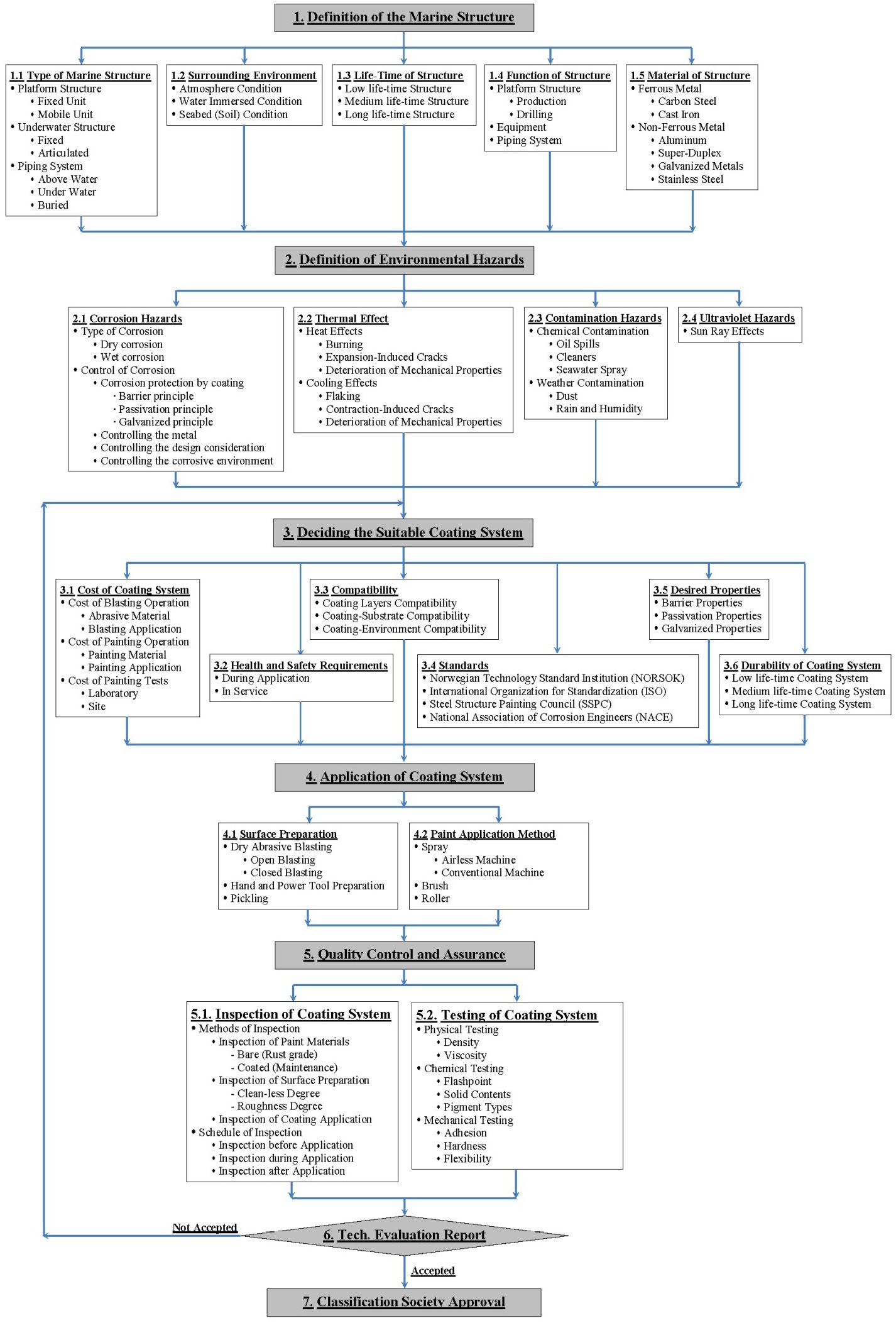
Steel is subject to a variety of corrosion phenomena including atmospheric corrosion, splash zone corrosion, crevice corrosion, and micro-organic corrosion, etc. (Revie, 2011). The harsh maritime environment quickly degrades any coating placed on damp steel, or over mill scale, or rust. Painting of the steel members are carried out on a well prepared surface in a painting shop, under the appropriate conditions of temperature, humidity and weather protection (Chandler and Bayliss, 1985; Bardal, 2004; Ghali et al., 2007). Fig. 3 depicts a newly proposed rational systematic flow diagram of an integrated marine coating system.
ABS (2007) require that the provisions for coating include description of general application conditions at coating shop, method and equipment for surface preparation, ranges of temperature and relative humidity, application methods, time between surface preparation and first coat, minimum and maximum dry film thickness of a single coat, number of coats and minimum total dry film thickness, relevant drying characteristics, procedure for repair of damaged coating, and methods of inspection (e.g., adhesion testing and holiday detection). Surface preparation and application of coating are carried out when the surface temperature exceeds 3
Sacrificial cathodic protection, adequately connected with the steel structure, is used to protect the exposed water-immersed zones, and installed in accordance with the relevant specifications to avoid their dislodging during transport, launching, installation, pile driving, and service. Impressed current is more effective as it is less likely to be shielded, but requires continued monitoring and regulation. Coatings having adequate resistance to cathodic disbandment, i.e. zinc/aluminum-based alloys, are applied to immersed structural members to minimize the requirements for cathodic protection.
Lifting, moving and up-righting the monopod stage
In consequence to the proposed all-ground horizontal construction phase of the monopod, a post-construction phase for the rational manipulation of the platform is also proposed. In applying such post-construction phase, the stages of interest are those of lifting, moving and up-righting of the monopod. Such post-construction phase is applied in handling a monopod platform in the PETROJET yard, and proves its reliability.
Before lifting the monopod, its weight components and center of gravity (
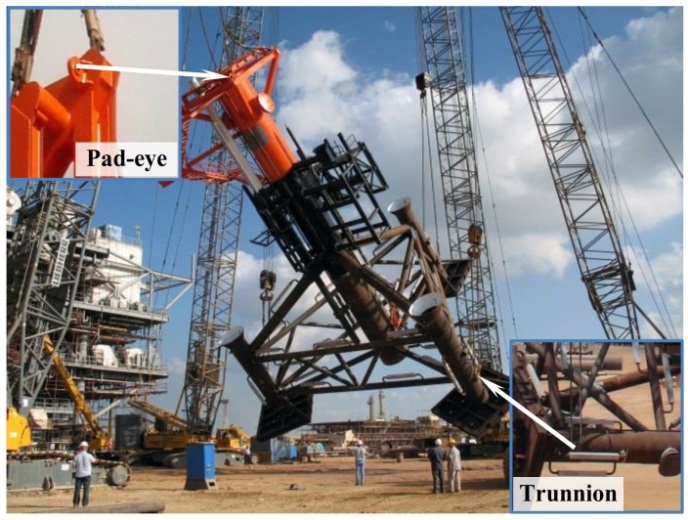
It is worth to mention that, the common lifting pad-eyes and trunnions are used in handling the platform in the conventional vertical construction and assembling scenario as well as in its transportation from the fabrication yard to the installation site. However, it is impractical and dangerous to use such conventional lifting devices in handling the platform in the proposed double phase fabrication scenario, as the slings may stick to the deck structure. Therefore, special temporal pad-eyes are installed in certain predefined positions on the platform representing its up-righting accessory. The principal purposes of such special temporal pad-eyes are to withstand the hanging reactions during the different up-righting stages, to use them as stabbing guides during the monopod deck installation, and avoid any obstruction in way of the cranes rigging tools. Fig. 4 illustrates the photographs of the pad-eyes and trunnion. The monopod is up-righted gradually starting from its initial horizontal position
vertical position
In generating the three dimensional FEM of the monopod, two types of coordinate systems are used; global and local coordinate systems. The global coordinate system is three dimensional right handed Cartesian orthogonal system comprising of three orthogonal axes
Each part, joint, element, or constraint of the monopod structural model has its own local right-handed Cartesian orthogonal coordinate system denoted 1, 2, and 3, and used to define the properties, loads, and response for that part, joint, element or constraints respectively. The local coordinate system may vary from joint to another, element to another, and constraint to another, but all are defined with respect to the global coordinate system. There is no preferred vertical direction for a local coordinate system. Fig. 5
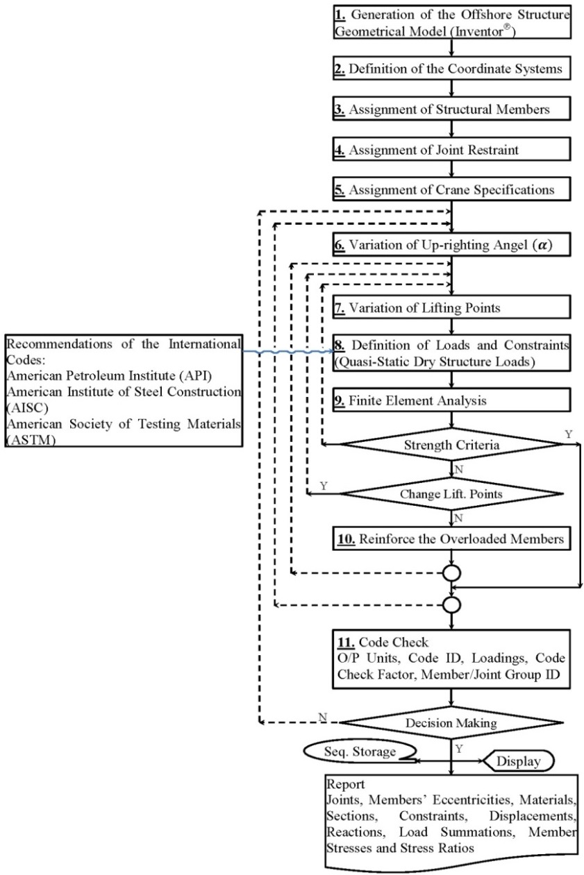
In the computer era, deciding, approving and then applying the triple post-construction phase of lifting, moving and uprighting the monopod relies on the powerful discrete analysis of FEM (Zienkiewicz et al., 2005; Bathe, 2007; MacDonald, 2007; Rao, 2010). Such method approximates the monopod continuous structure of infinite degrees of freedom to its discretized structural model of finite degrees of freedom, using an aggregate of finite arbitrary elements. FEM calculates an approximate numerical solution of the monopod equilibrium equations, the constitutive equations, the strain-displacement relations, and the compatibility equations subjected to certain boundary conditions, and thus predict the monopod handlinginduced loading effects.
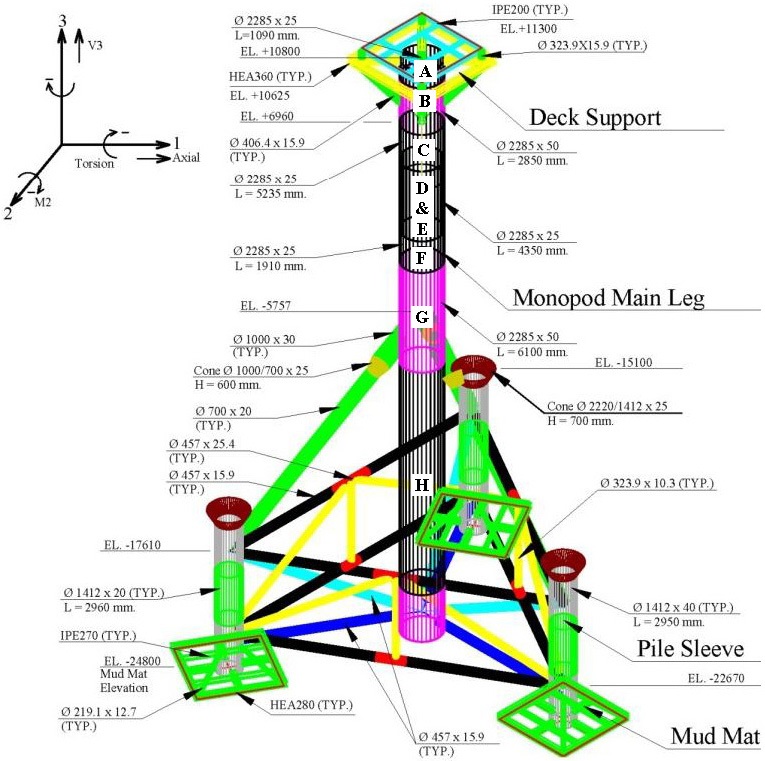
Fig. 5 depicts the geometry, terminologies, dimensions and scantlings of the monopod platform together with the coordinate system adopted in the present numerical analysis. The monopod model may be created using the modeling processor incorporated into either AutoCAD® (2012) or Inventor® (2012) application; however, the latter is used throughout this investtigation. In modeling the monopod, all principal structural members and appurtenances are included; whereas, the topside and the boat landing decks, and the stairs are excluded. A frame property with different types of members matching the Euro standard, with three translational and three out-of-plane rotational nodal displacements, is used to generate the model of the tubular members. A mesh of sufficient fineness and appropriate geometry enough to produce reliable numerical results is used in performing the structural analysis of the monopod, pad-eyes and trunnions in the post-construction phase according to the systematic procedures depicted in Fig. 6.
The present numerical investigation is performed within the framework of the three dimensional linear modeling and analysis, and quasi-static loading in a windless environment. Therefore, the only considered loads are those due to gravity, with an appropriately considered safety margin of %30 (AISC 303-10, 2010) to reflect any sudden inconvenient dynamic loads due to weather fluctuations, human errors, or rigging malfunction/deterioration. In addition to the structural analyses, the connections of all tubular joints are checked to analyze the strength of tubular joints against punching.
NUMERICAL ANALYSIS OF THE UP-RIGHTING-INDUCED STRESSES AND DISPLACEMENTS
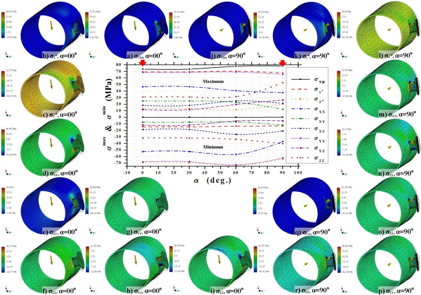
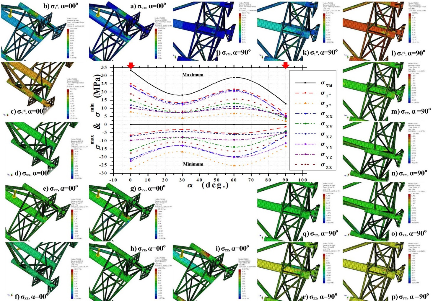
Figs. 7,9 and 11 show the variation of maxima and minima of the up-righting-induced stresses
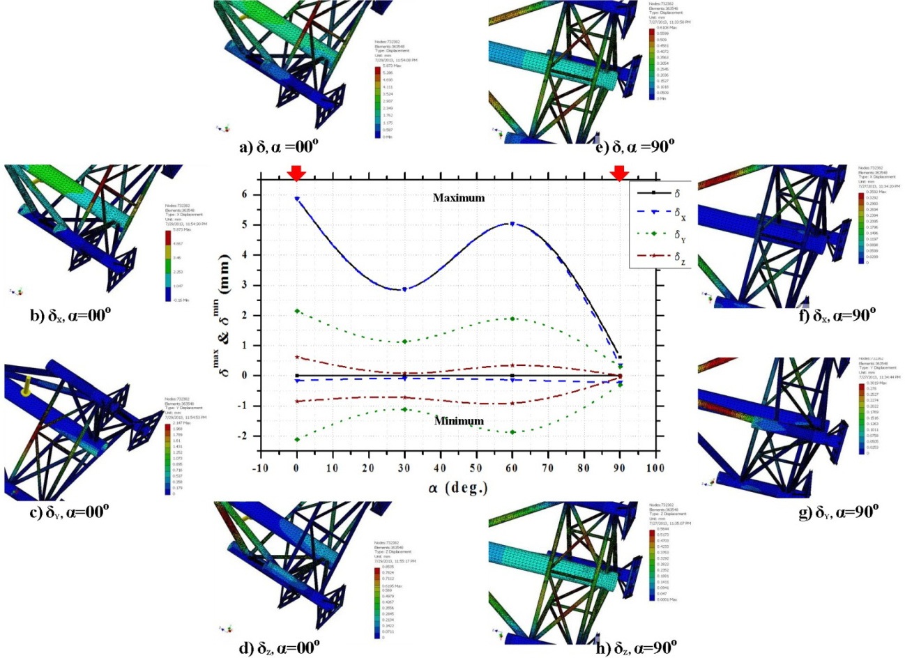
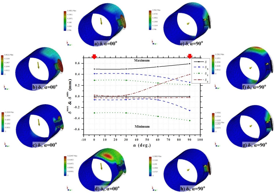
Figs. 8,10 and 12 show the variation of maxima and minima of the up-righting-induced displacements
>
Up-righting-induced stresses in the monopod
On both sides of Fig. 7, all stresses behave harmonically with each stress records two humps (peaks) at
>
Up-righting-induced displacements in the monopod
On both sides of Fig. 8, except

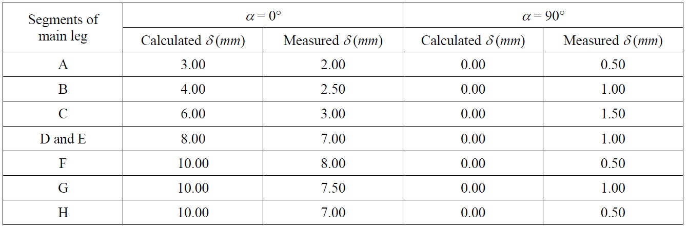
Calculated versus measured displacements at different segments along the naked monopod main leg.
Table 2 verifies the calculated displacements versus the measured ones at eight segments “A ? H” of the naked monopod main leg (excluding deck supports, all braces, pile sleeves and mud mats). The “A ? H” segmentation is performed as shown in Fig. 5, with “A” and “H” refer to the upper and lower ends of the monopod caisson respectively. The displacements are measured at two up-righting angles
>
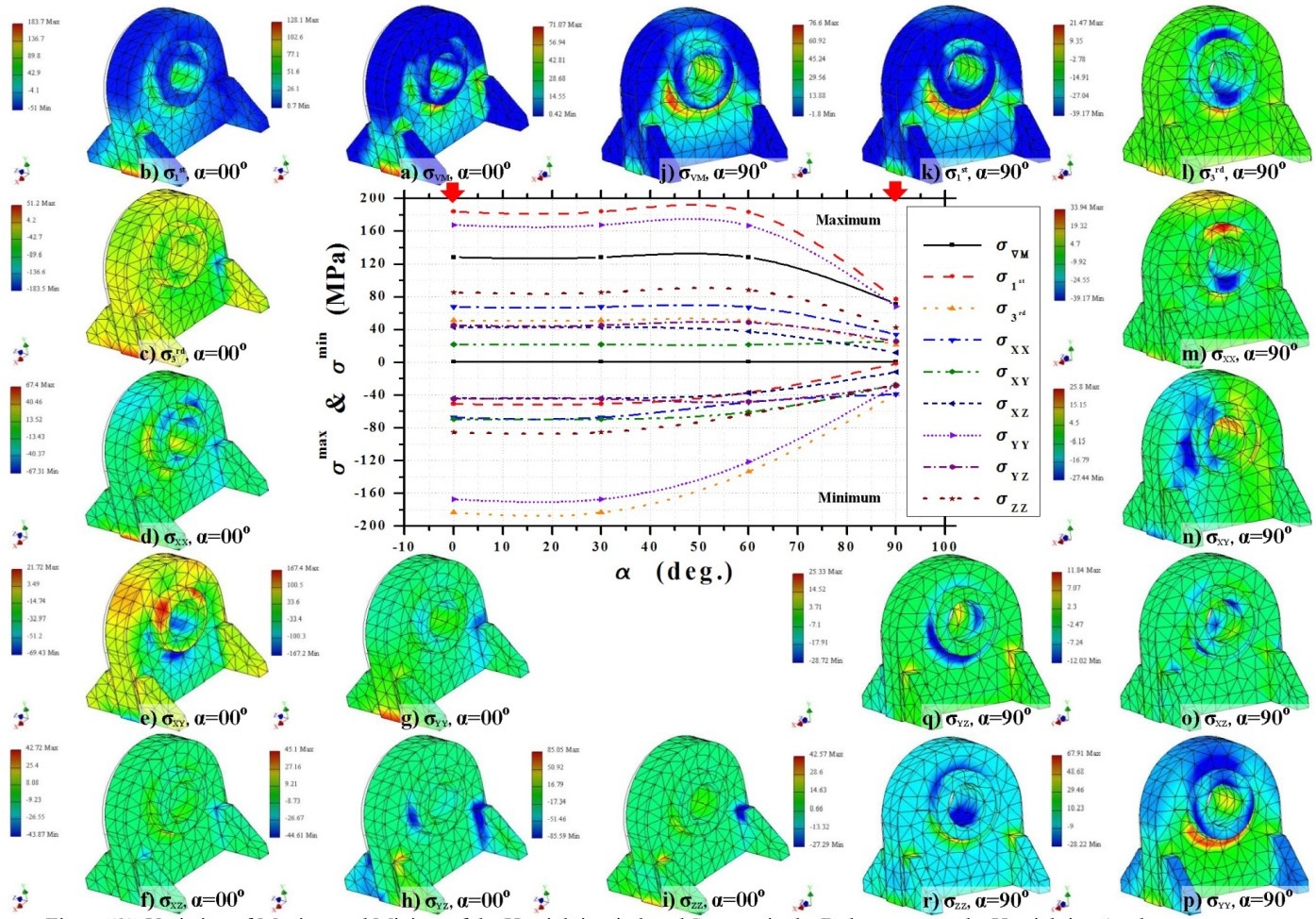
Up-righting-induced stresses in the pad-eye
On the maximum side of Fig. 9, all stresses keep constant as
>
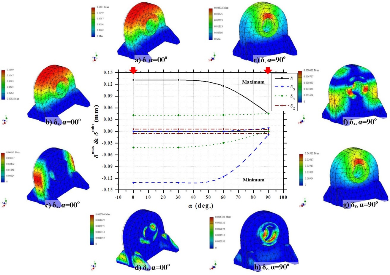
Up-righting-induced displacements in the pad-eye
On the maximum side of Fig. 10, all displacements keep constant as
>
Up-righting-induced stresses in the trunnion
On the maximum side of Fig. 11, as
>
Up-righting-induced displacements in the trunnion
On the maximum side of Fig. 12, as
CONCLUSIONS AND RECOMMENDATIONS
This paper investigates a novel double phase rational scenarios for the fabrication of an offshore monopod platform. The first phase; all-ground horizontal construction, is practically investigated; whereas, the second phase; post construction, is investigated numerically. Following is a brief investigation of the principal conclusions associated with few future recommendations that may rely on this research work.
1. The application of all-ground horizontal construction and its consequent post-construction operations is not a platform sizelimited, instead it is applicable to large and medium sized platforms too as it is influenced only by the available yard fabrication facilities and layout, (sub) assemblies handling facilities and capacities, and adequacy and capabilities of the temporal and permanent platform lifting devices.
2. As a matter of manufacturing project management, the application of all-ground horizontal construction and its consequent post-construction operations, along with the associated simultaneous (pre) fabrication and (sub) assembly processes, saves almost four months of fully laden fabrication hours in terms of the included costs, i.e. machining cost, staff salaries, reservation of the yard resources (area, staff, machines, etc.) for another project.
3. As a matter of overall project management, the application of all-ground horizontal construction method and its consequent post-construction operations (lifting, moving, and up-righting) saves almost six days of the load-out and sea fastening time in terms of the crane-barge standby cost.
4. Erroneously fabricated platform; structure, systems, materials and/or equipment, associated with their unsuitability for the intended purpose represents contribution to the platform owner’s future maintenance costs, and the PETROJET future lack of credibility. Therefore, beyond its fabrication experience, PETROJET collects service experience via well experienced staff inspecting, scrutinizing, and analyzing the gains of the previously fabricated platforms worldwide.
5. As a matter of viciousness of the corrosion ramified initiation and propagation followed by the highly expensive downtime and rework of the platform, a rational protective coating system that depends on a properly monitored and well maintained scenario is proposed. The details and applicability of the proposed protective coating system based on a decision making tree are kept for a separate future paper.