In a postulated severe core damage accident in a PHWR, multiple failures of core cooling systems may lead to the collapse of pressure tubes and calandria tubes, which may ultimately relocate inside the calandria vessel forming a terminal debris bed. The debris bed, which may reach high temperatures due to the decay heat, is cooled by the moderator in the calandria. With time, the moderator is evaporated and after some time, a hot dry debris bed is formed. The debris bed transfers heat to the calandria vault water which acts as the ultimate heat sink. However, the questions remain: how long would the vault water be an ultimate heat sink, and what would be the failure mode of the calandria vessel if the heat sink capability of the reactor vault water is lost?
In the present study, a numerical analysis is performed to evaluate the thermal loads and the stresses in the calandria vessel following the above accident scenario. The heat transfer from the molten corium pool to the surrounding is assumed to be by a combination of radiation, conduction, and convection from the calandria vessel wall to the vault water. From the temperature distribution in the vessel wall, the transient thermal loads have been evaluated. The strain rate and the vessel failure have been evaluated for the above scenario.
Pressurized Heavy Water Reactors (PHWRs) have engineered safety systems to restore the reactor to a safe state in the event of an accident. Most of the safety systems have diverse and redundant features. The purpose is to enhance the availability of these safety systems so that failure of one of them does not lead to a progression of accidents. Besides, the reactors have multiple barriers to arrest the release of activity if a hypothetical accident progresses with the failure of the safety systems.
In spite of all these, a low probability accident can be cast beyond the acceptable design basis envelope, which can progress to a severe accident. Severe accidents which arise due to multiple failures of safety systems are beyond design basis accidents and lead to significant core degradation. Whatever be the initiating event, a severe accident occurs when the heat generation rate exceeds the heat removal rate. The fuel is unable to get cooled and gets damaged, leading to its melt down. The severity of such an accident depends on the nature and extent of the core damage during the accident progression. Of course, these accidents have very low probability of occurrence, but certainly they have high risk in terms of consequences to the plant personnel and public. In view of this, most of the new generation reactors are designed with built-in severe accident management strategies. The nuclear utilities also plan to extend or build additional safety features in existing plants in order to enhance the defense-in-depth of these plants so as to cope with such severe accidents.
Several scenarios can be postulated, which lead to such core melt down accidents. It can be initiated with a Limited Core Damage Accident (LCDA) which can involve single or multiple channels. For example, a feeder break can result in overheating of the fuel in the affected channel. Or a loss of coolant accident (LOCA) with loss of the Emergency Core Cooling (ECC) system could lead to widespread fuel damage [1]. In both cases, if moderator is available as a secondary heat sink, it can prevent the failure of fuel channels and core degradation. For an accident to proceed to significant core damage, there must be failure of multiple fuel channels. This is possible with the loss of moderator as a heat sink in the case of prolonged Station Black Out (SBO) [2]. The Severe Core Damage Accident (SCDA) may be initiated from an LCDA and progress to significant core damage with the non-availability of moderator as a heat sink. Hence, the early stage of SCDA in heavy water reactors is different from that of a light water reactor in that the presence of a heavy water moderator slows down the progression of core disassembly. Such multiple failures may lead to the collapse of pressure tubes and calandria tubes, which may ultimately relocate inside the calandria vessel forming a terminal debris bed. With time, this moderator gets evaporated and after some time, a hot dry debris bed generating heat is retained in the calandria vessel. The terminal debris ultimately melts down and forms a molten corium pool in the calandria vessel. The molten corium pool is surrounded by calandria vault water which removes the decay heat from the corium.
In the present study, a numerical analysis is performed to evaluate the thermal loads and the stresses in the calandria vessel following the above accident scenarios in case of a PHWR. The heat transfer from the molten corium pool to the surrounding is assumed to be by a combination of radiation, conduction through the wall of the calandria vessel, and convection from the calandria vessel wall to the vault water. From the temperature distribution in the vessel wall, the transient thermal loads have been evaluated. The strain rate and the vessel failure in the lower head have been evaluated for the above two scenarios.
2. PHENOMENOLOGY OF ACCIDENT PROGRESSION WITH STATION BLACK OUT (SBO) AS AN INITIATING EVENT
In the present study, SBO has been considered as the postulated initiating event with unavailability of various safety systems leading to severe accident progression. The scenarios considered in the present analysis are as follows:
Class III and IV power unavailable for sufficiently long time
Moderator cooling and shield cooling are unavailable
Shut down cooling not available
Main and auxiliary feed water are unavailable
Steam generator (SG) main steam safety valves are available, they open and close at set point to relieve pressure
Turbine main stop valves are closed after accident initiation.
Emergency core cooling system unavailable
With unavailability of Class IV and Class III power, the pumps are tripped. Immediately the reactor gets tripped. Though the pump motor is not working, because of the flywheel inertia and availability of a heat sink on the secondary side, thermosyphon flow is established and decay heat is removed from the core by thermo-syphon till the heat sink is available. Since the main steam isolation valve gets closed, the secondary side steam generator pressure starts rising. When it crosses the relief valve set point, the relief valve opens. As a result of which, the inventory in the SG continuously depletes. When the secondary side inventory is boiled off, the heat sink is lost and primary side pressure starts rising. When primary pressure exceeds the liquid relief valve set point, it opens and the primary side inventory is released to the containment. As the inventory from the primary side is lost, the fuel, sheath and pressure tube (PT) temperatures start rising. At a particular temperature (around 900 K), the PT balloons and contacts the calandria tube (CT). This causes heat removal through PT and CT to the moderator. The moderator temperature starts rising, and ultimately it starts boiling. Increase in calandria pressure causes the rupture disc to blow off, releasing the moderator to the containment and depleting the moderator level in the calandria. This causes uncovery of top channels. Due to unavailability of the moderator as a heat sink, the fuel, sheath, PT, and CT temperature start rising very fast, which leads to channel disassembly. The channels are relocated into the remaining moderator in the form of debris inside the calandria vessel. After some time, the moderator evaporates and forms the dry debris, generating heat. The debris ultimately melts down and forms a molten corium pool in the calandria vessel. The molten corium pool is surrounded by calandria vault water which works as a heat sink. With time, if no replenishment of cooling water into the calandria vessel is provided, the vault water also boils off and gets depleted. Subsequently, the calandria wall temperature starts rising. This causes development of thermal and structural stresses in the calandria and ultimately it may fail.
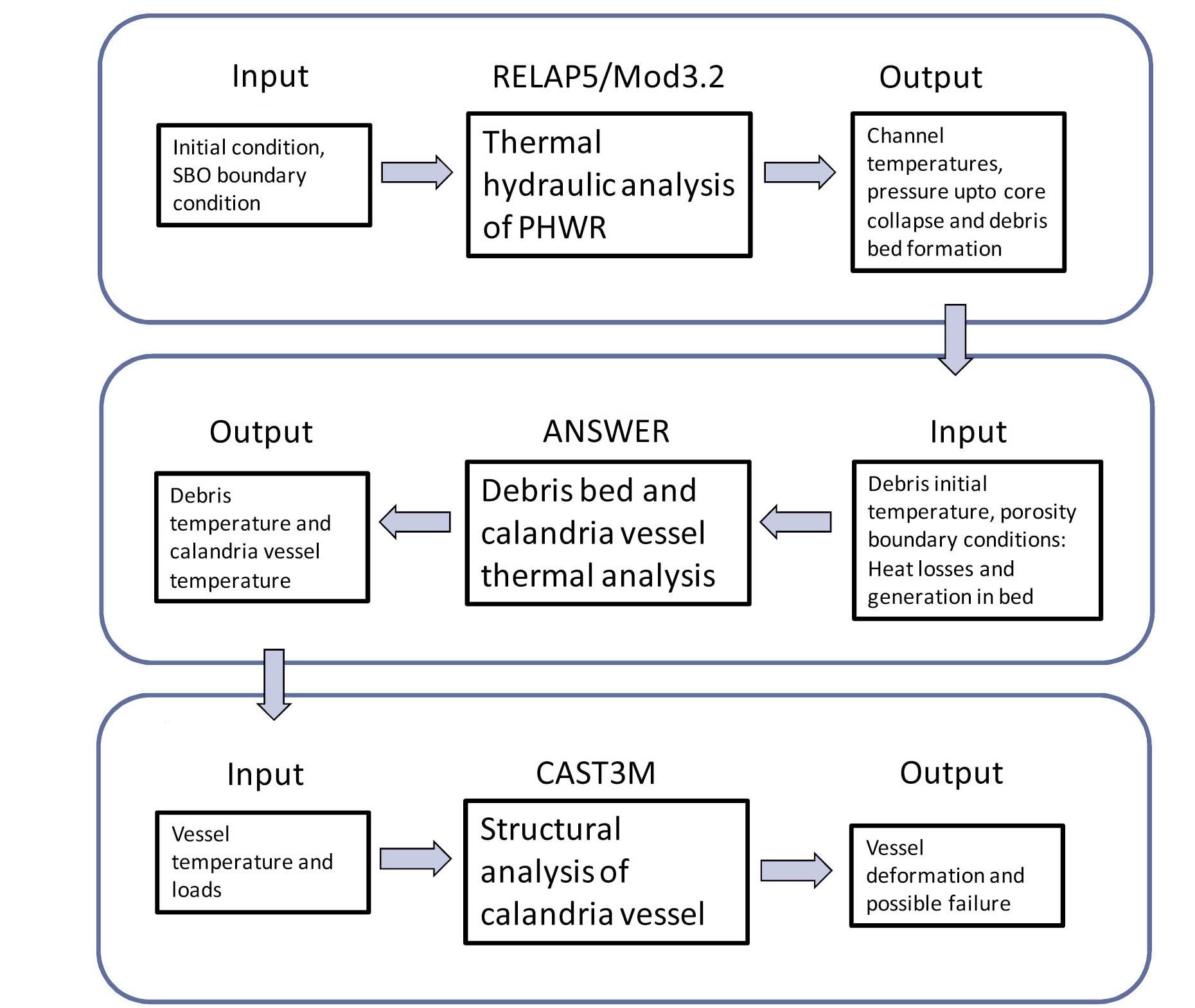
In this work, thermal and structural analysis of a PHWR calandria vessel was carried out using different codes. A schematic diagram of the analysis process is as shown in Fig 1. Three different codes have been used for analysis, namely RELAP5/Mod3.2, ANSWER and CAST3M. A brief description of the codes is given as follows:
Thermal Hydraulic models of the RELAP5/Mod3.2 code have been used for simulation of the heat transport system of a PHWR plant. The RELAP5/Mod3.2 code has been developed for best estimate simulation of light water reactor coolant systems during normal operation conditions as well as accidents. The code is based on the two fluid model which uses six equations for solving the mass, momentum, and energy conservation for the two phases i.e. water and steam. The code has been extensively used for simulation of nuclear thermal hydraulic systems.
The ANSWER™ software package is a comprehensive mathematical model for simulation of fluid flow, heat and mass transport processes in laminar or turbulent, compressible or incompressible flows in porous media. ANSWER™ solves a set of coupled transport equations for fluid velocities, pressure, temperature, and concentration of chemical species in multi-phase or multi-fluid, variably saturated, fractured or porous media flow. The modified energy equation for porous medium used for present analysis is as given below.
Energy Equation:
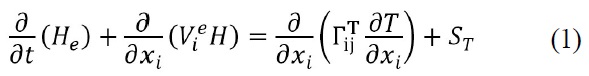
Where:
He is the effective enthalpy per unit volume of porous media
V is the effective velocity of the component for fluids in ith direction
H is the total enthalpy of fluid per unit volume

is the effective diffusion coefficient for heat
ST is the rate of heat generation per unit volume
The effective enthalpies of the solid and fluid are given as
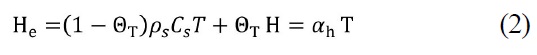
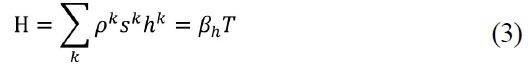

Where
hk is the enthalpy of kth phase per unit mass
ΘT is the total porosity of the matrix
Cs is the specific capacity of the solid matrix
ρs is the density of the solid
T is the temperature
CAST3M [3] is a computer code for the analysis of structures by the finite element method (FEM). In CAST3M, different types of analyses (strains or stresses plane, axisymetry, etc.) can be done. Also, different types of elements (beams, hulls, etc.), material properties and geometrical characteristics which cannot be deduced from the meshes and the boundary conditions can be modelled. Different types of material behaviour models like elastic, plastic, elasto-plastic, viscoelastic, viscoplastic, etc. can be used in the code. In the present problem, elasto-viscoplastic analysis with the Chaboche model has been carried out.
4. THERMAL HYDRAULIC ANALYSIS OF PHWR DURING SBO
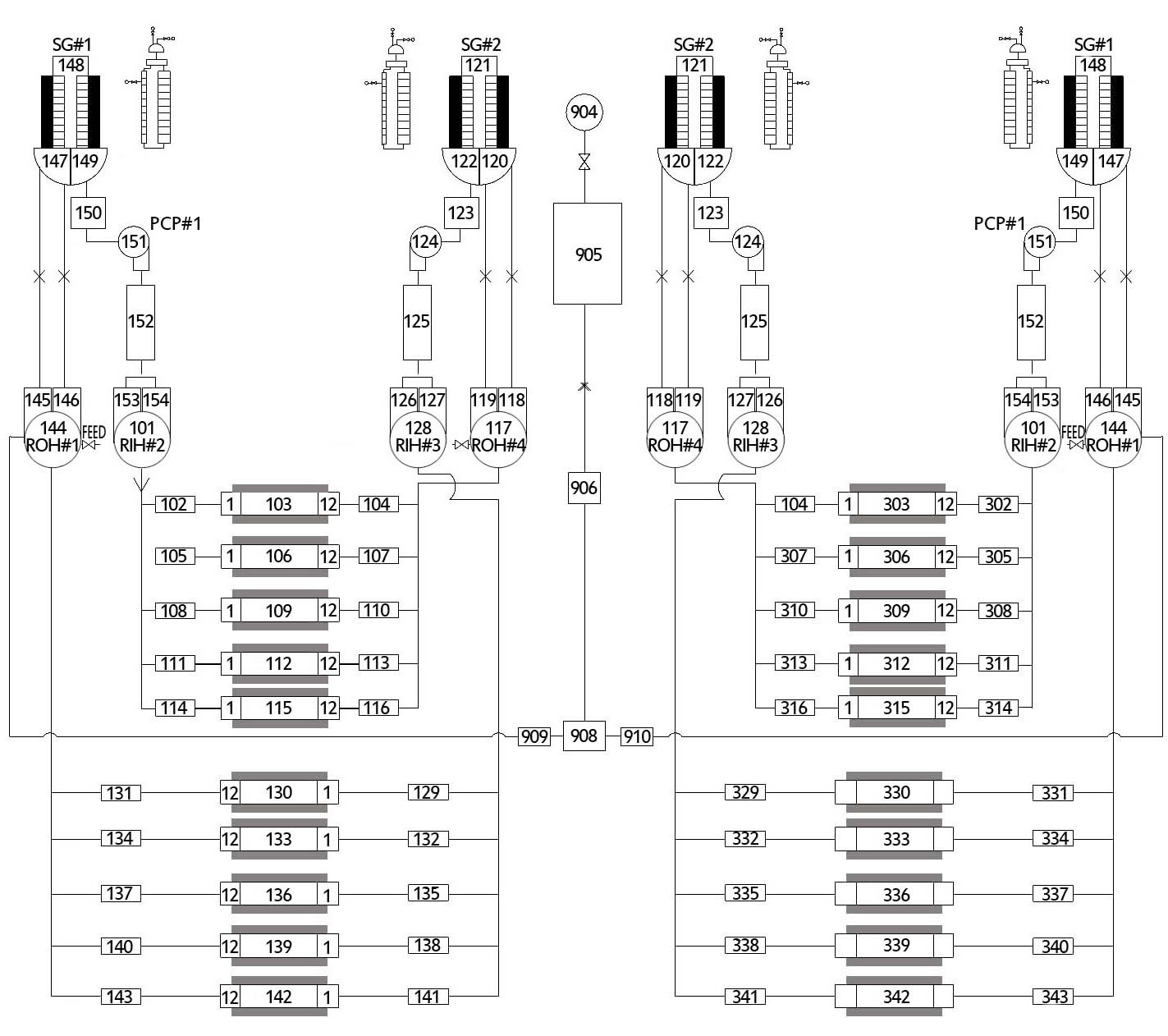
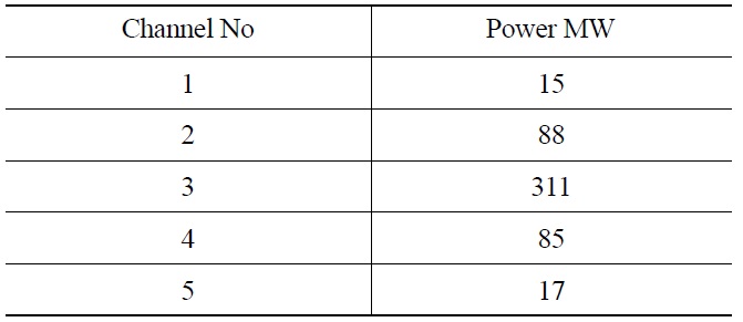
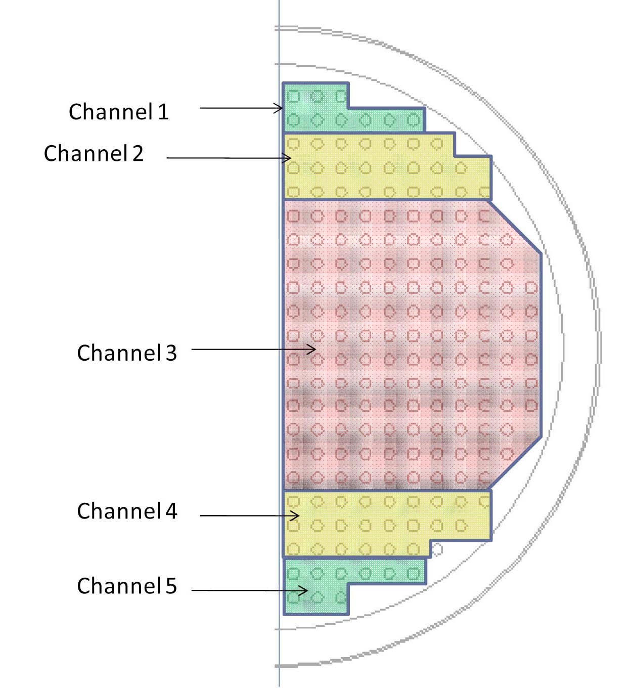
Thermal hydraulic analysis of PHWR leading to the core disassembly was carried out using the computer code RELAP5/Mod3.2 [4]. The Primary and Secondary Heat Transport System of the PHWR has been modeled in RELAP5/Mod3.2 as shown in Fig 2. Channel 1, 2, 4 and 5 are low power channels whereas channel 3 is the hottest channel. The locations of these channels and number of clubbed channels in the core are shown in Fig 3 and their powers in Table 1. The secondary system consists of a steam generator (SG) downcomer, riser, steam separator, and steam dome. The turbine has been simulated with a Time Dependent Volume (TDV) acting as feed water pumps. The moderator system has also been modeled, consisting of the calandria as a pipe component and considering heat loss through PT and CT to the moderator.
At time t = 0, the SBO is initiated. The boundary conditions are imposed as follows:
All the pumps tripped
Reactor is tripped and it is generating decay heat
Feedwater flow rate reduced to zero
Moderator circulation pump tripped
Main steam isolation valve is closed

Channel Powers
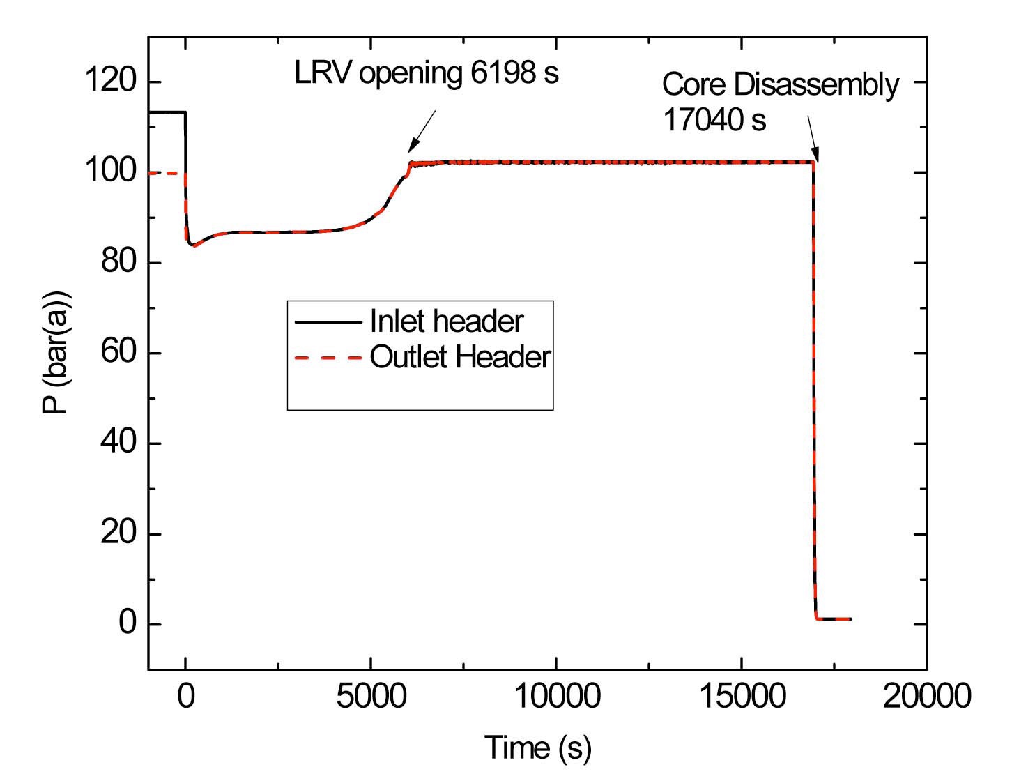
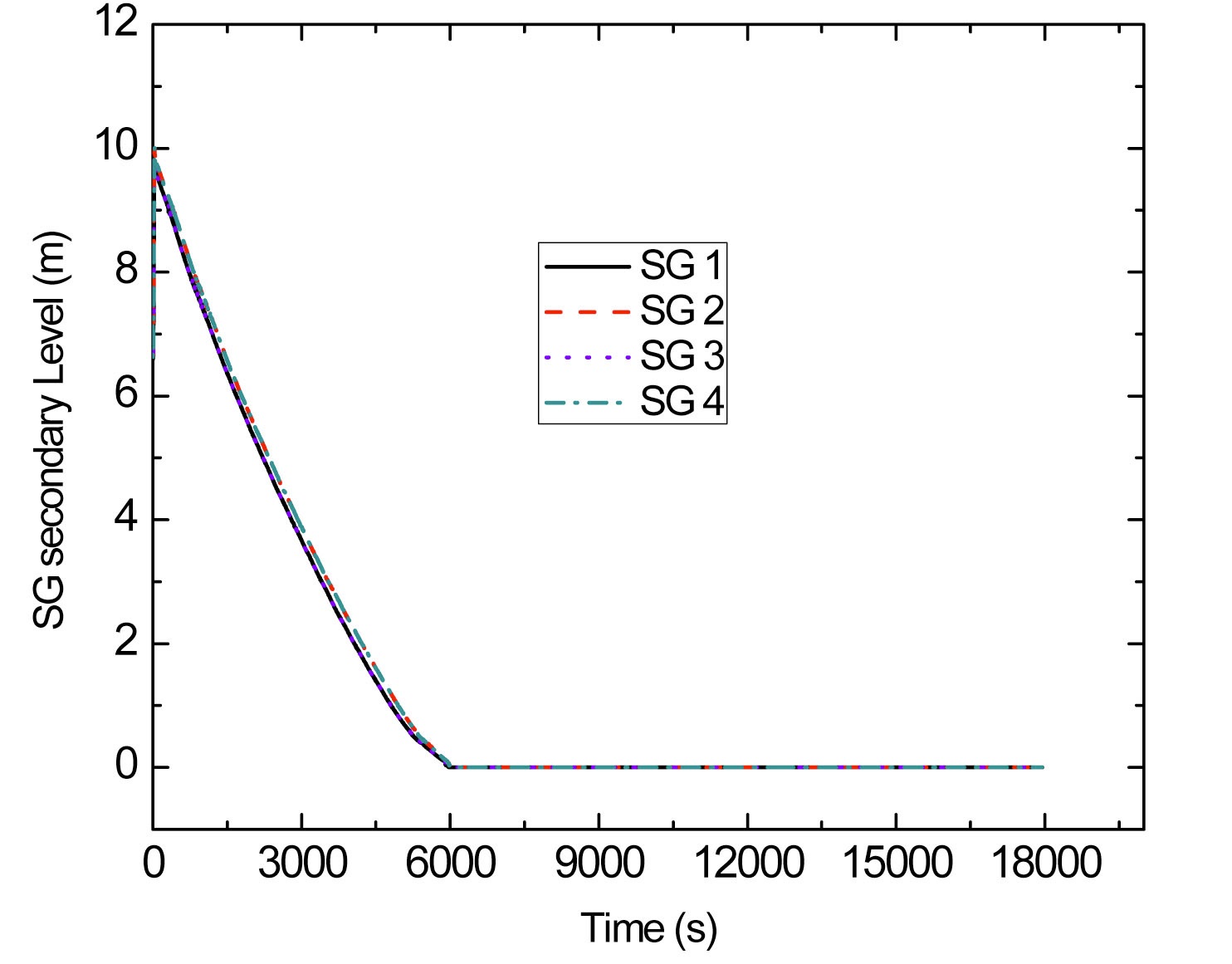
With these boundary conditions, the thermal hydraulic behaviour of the plant was studied. As a result of pump tripping and the reactor shutdown, slight depressurization of the primary system is observed. The pressures in the outlet and inlet header are shown in Fig 4. Due to the closure of the secondary side, the secondary side pressure rises and is relieved by the opening of the Main Steam Safety Valves. As a result of which, the inventory in the SG continuously depletes (Fig. 5).
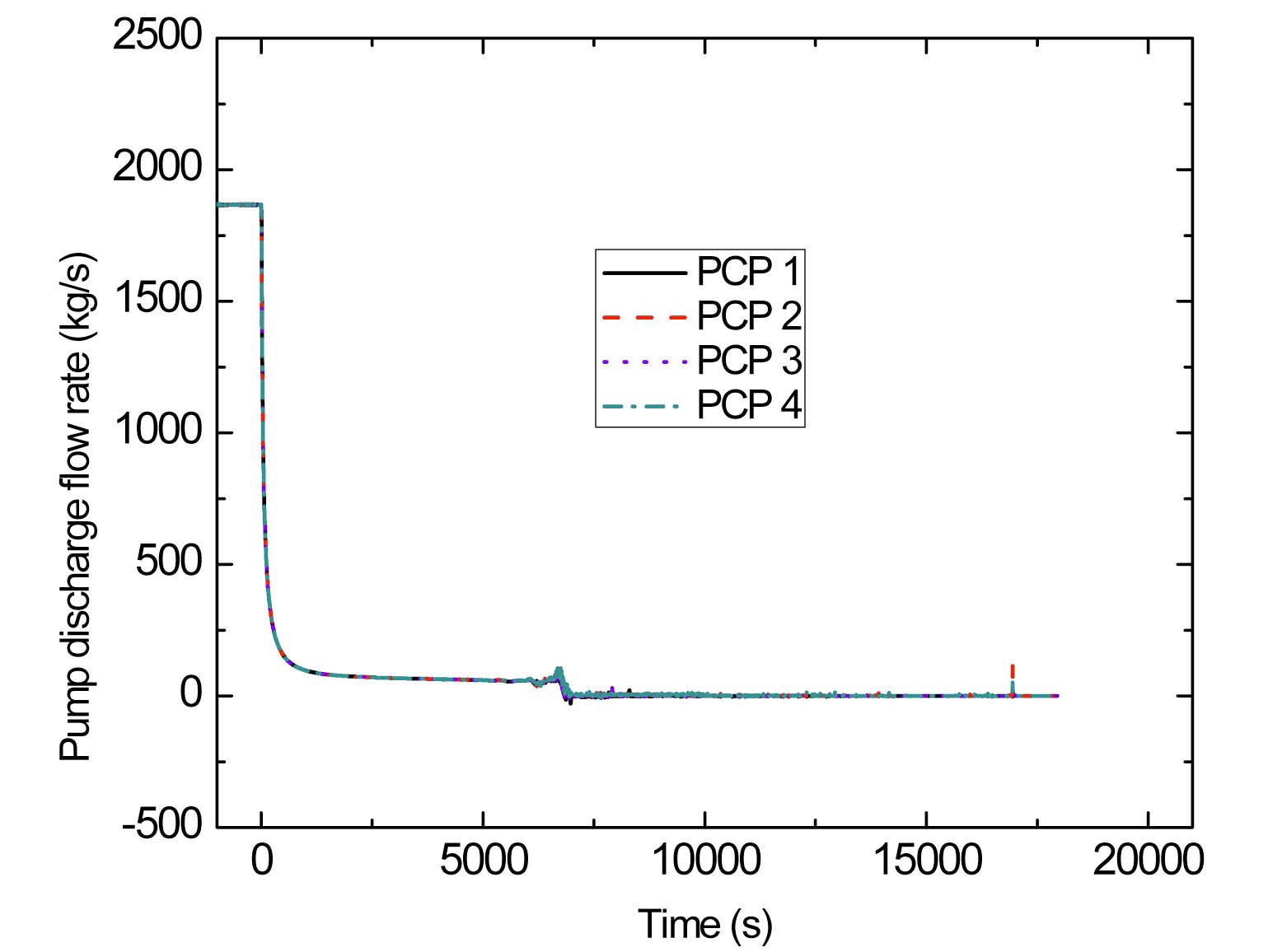
At around 6000 s, the inventory in all four SGs is completely boiled off. As a result, the primary side pressure rises to the set point of the relief valves at around 6200 s (Fig. 4). When the pressure increases above the relief valve set point, it opens and discharges the inventory into the containment. During this time, the inventory in the primary side depletes. The mass flow rate in the primary side is shown in Fig. 6. After tripping of the pumps, the mass flow rate reduces. The residual flow is due to the combined
action of the pump coast-down initially and then the gradual build up of thermosyphon. However, after nearly 6500 s, the thermosyphon flow rate becomes very small because
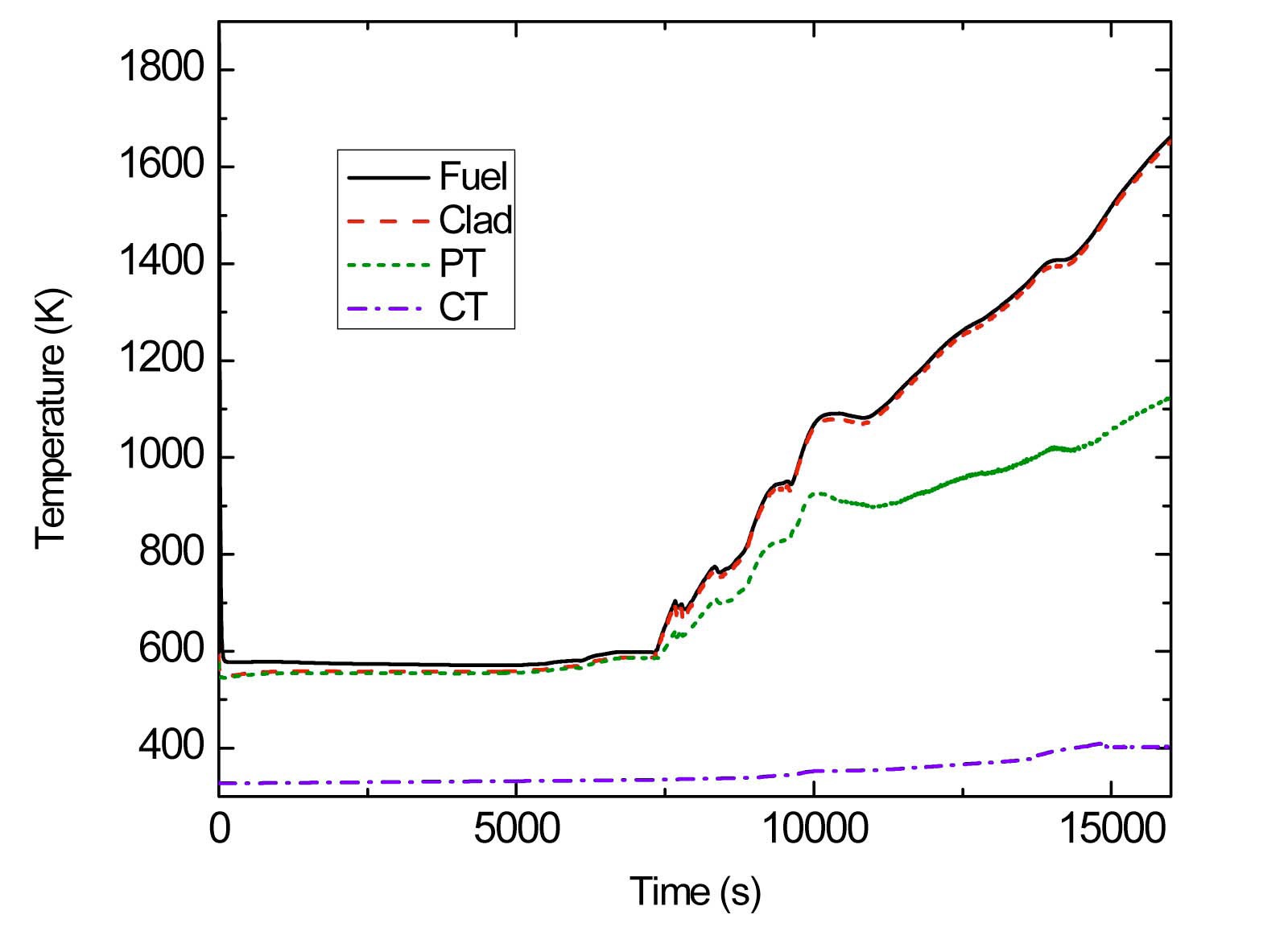
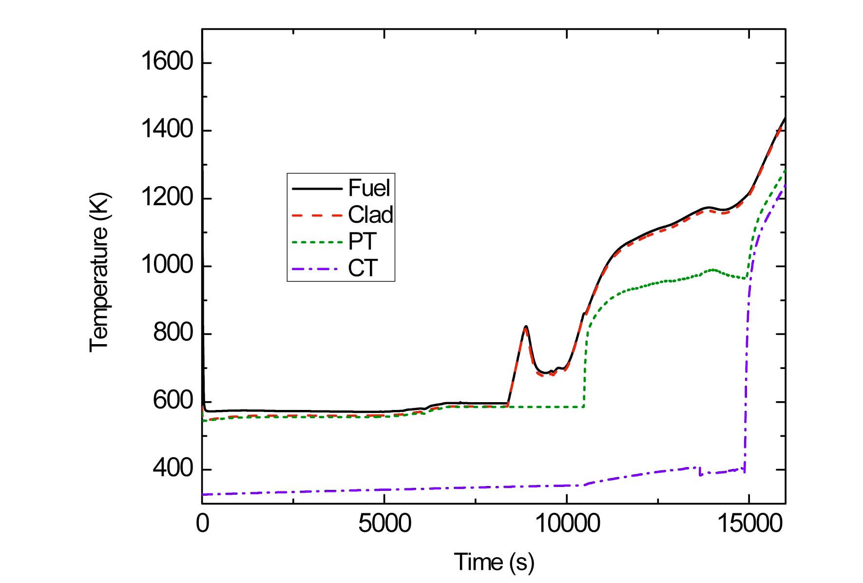
of no heat removal from the secondary side. Due to this, channels get completely voided. As a result, the fuel and clad temperature start rising. The temperatures of fuel, sheath, PT, and CT for channel 1 (low power) and channel 3 (hottest) are shown in Figs. 7 and 8.
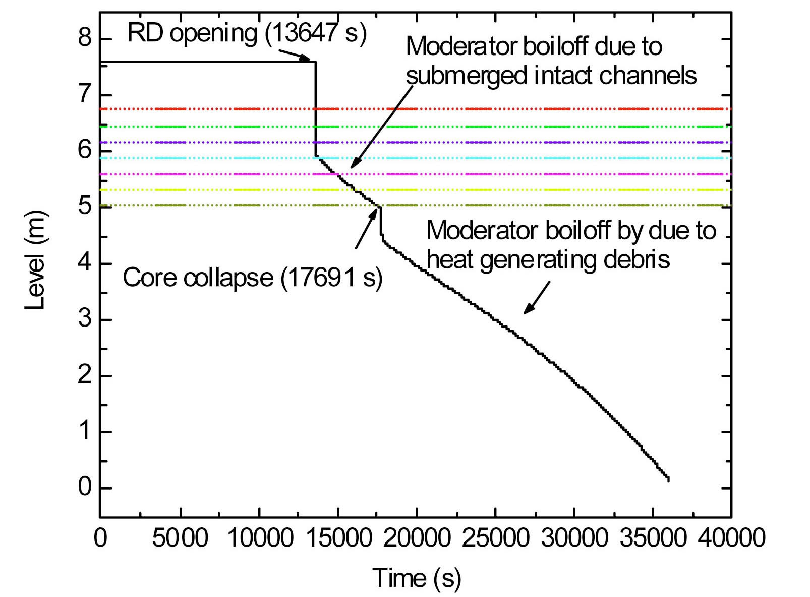
Since the channels are completely voided and there is no flow, the clad surface temperature starts rising after 6000 s. After around 7500 s, the sheath temperature starts rising significantly in the hottest channel (Channel 3, Fig. 8), whereas for low power channels it starts rising after 8500 s. At around 10000 s, the temperature of the PT rises to about 900 K for channel 3. At this temperature, together with high pressure conditions, the PT balloons and contacts the CT. For low power channels the contact occurs at nearly 11000 s. Subsequent to contact, the PT temperature does not rise further. At the same time, heat transfer to the moderator in the calandria vessel as a result of PT-CT contact increases. It leads to a pressure increase inside the calandria. At around 13647 s, the calandria rupture disc bursts. It leads to flashing of liquid inside the calandria causing the calandria level to drop to about 6 m (Fig. 9). As a result, the top two channels (1 and 2) get uncovered.
This leads to an increase in the CT temperature of channel 1 (Fig. 7) whereas channels 3-5 remain submerged and their CT temperatures are lower. When the CT average temperature reaches 1473 K, channel disassembly takes place at 17040 s for channel 1 and 2, whereas the other channels (3-5) are still intact. Due to the disassembly of uncovered channels, the primary pressure reduces to atmospheric pressure (Fig. 4) at around 17040 s. During this time, the calandria boiloff is taking place and the level continuously decreases. At approximately 17691 s the level falls to 5 m which corresponds to uncovery of 7 rows. After 7 rows are exposed, the core is considered to be collapsed. After the core collapses, the remaining water from the calandria is evaporated.
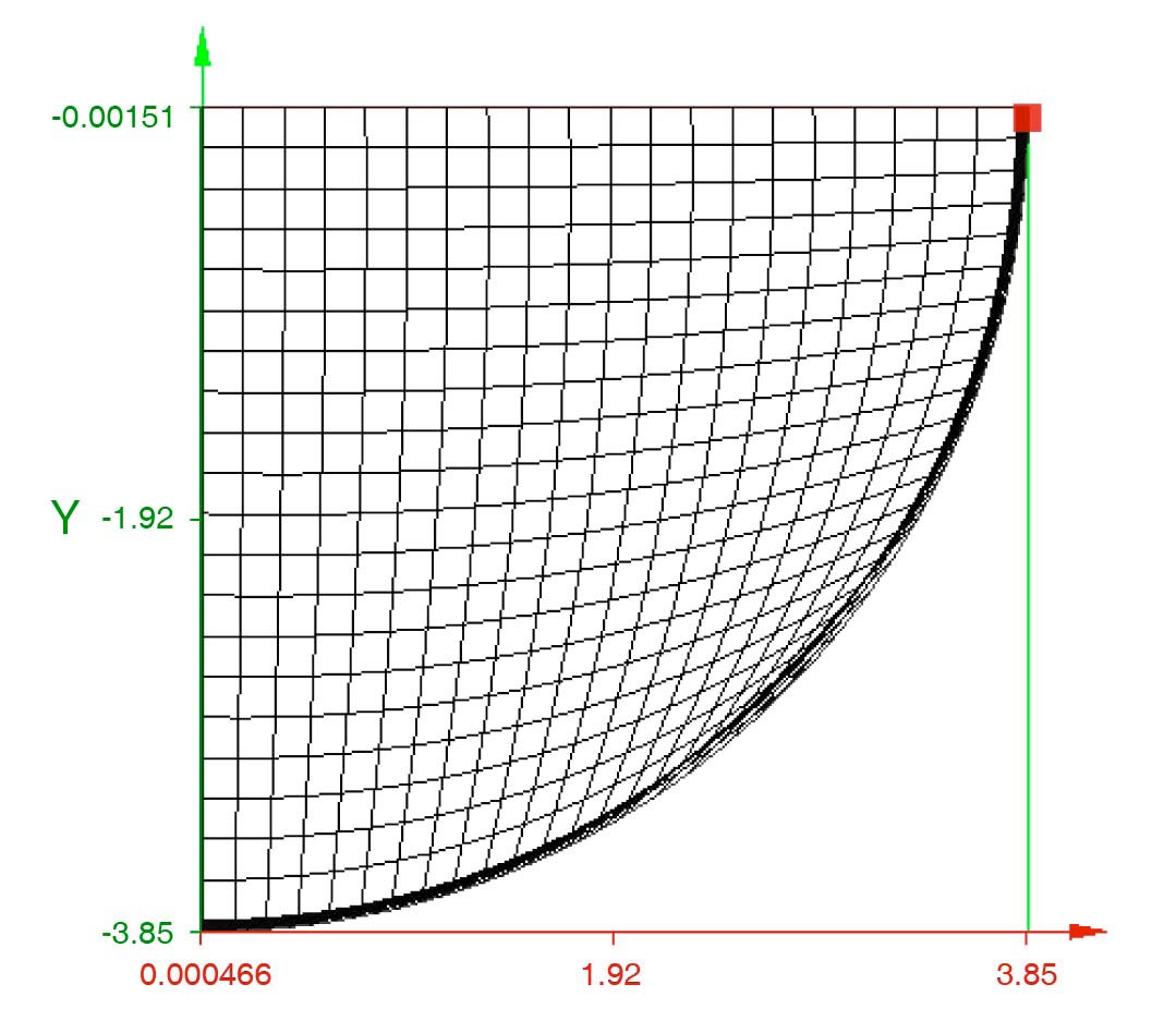
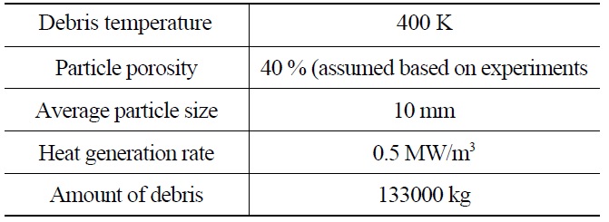
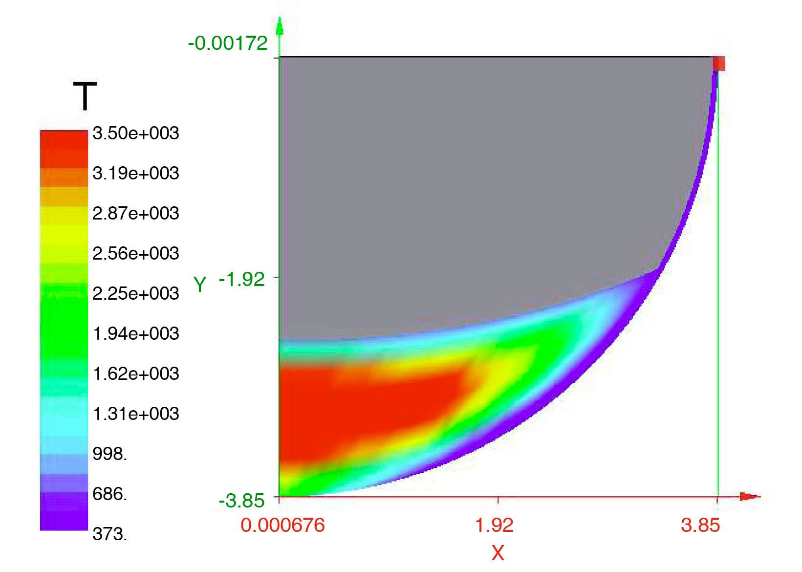
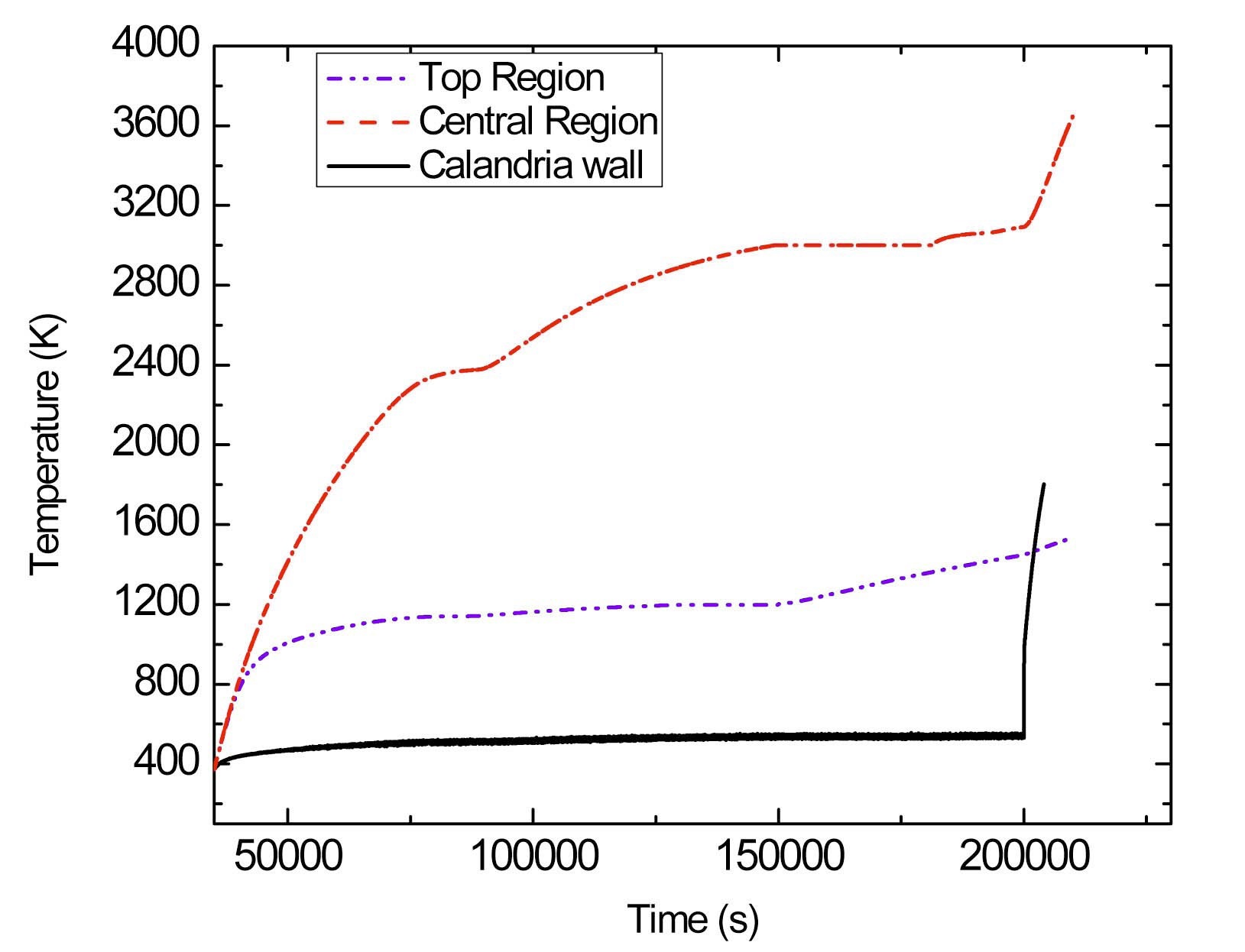
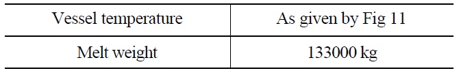
After boil-off of the moderator at around 35000 s (Fig. 9), the temperature of the debris continuously increases. The heat transfer in the dry debris and its melting have been simulated using the code ANSWER. The nodalization scheme of the debris is as shown in Fig. 10. The heat transfer from the debris to the calandria wall is considered to occur by a combination of conduction and radiation, and from the calandria wall to the vault water by nucleate boiling. The initial conditions for analysis are given in Table 2. Fig. 11 shows the temperature in the debris region and calandria vessel wall. The debris in the central region
[Table 2.] Initial Conditions for ANSWER Analysis

Initial Conditions for ANSWER Analysis
is found to be at very high temperature compared to the bottom and top. This is due to poor thermal conductivity of the debris bed. At the bottom part, due to a large heat sink, the temperatures are near the saturation temperature of water. After the vault water is evaporated, the calandria wall temperature starts rising after about 200000 s as shown in Fig. 11. Fig. 12 shows the temperature distribution inside the debris. It can be seen that most of the debris in the central region is in molten state, and temperature decreases towards the wall while the reactor vault water is still available for cooling the calandria vessel wall.
5. STRUCTURAL ANALYSIS OF THE CALANDRIA VESSEL
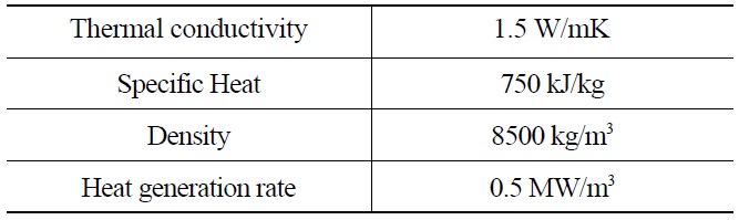
An analysis of the thermal stresses inside the calandria wall was carried out using the Finite Element Method code CAST3M, taking the boundary conditions predicted from the thermal hydraulic calculations. All the calculations were performed with large displacements and large rotations and employing the Chaboche Viscoplastic model; details of this constitutive model are explained in Ambroziak et al [5]. The initial conditions for the analysis are listed in Table 3. The thermal properties of corium are given in Table 4. Half cylindrical geometry has been modeled in 3D as shown in Fig. 13. Cub8 (8 noded) elements (40 No. in circumferential direction, 10 in longitudinal direction and one element in thickness direction) are used.
Fixed boundary conditions were applied at the end of the calandria vessel. A symmetry boundary condition was applied in the longitudinal directions of the calandria vessel. The temperature loading was applied to the calandria vessel which is varying with time. The dead weight of
[Table 3.] Initial Conditions for CASTEM Analysis
Initial Conditions for CASTEM Analysis
[Table 4.] Corium Debris Thermal Properties

Corium Debris Thermal Properties
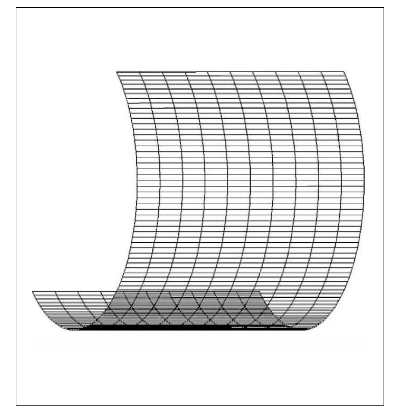
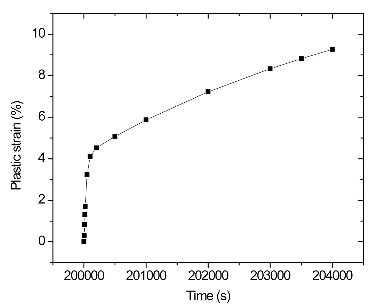
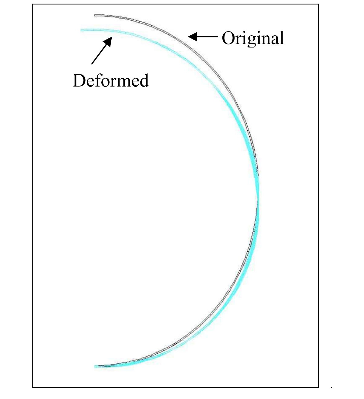
the molten pool has also been considered in calculations. All material characteristics used in the calculations were taken from the ASME Section II [6]. Material constants for the Viscoplastic Chaboche model were taken from Chellapandi et al. [7]. Plastic strain accumulation in the calandria under thermal and structural loading was calculated. Fig. 14 shows the maximum plastic strain accumulation in the calandria wall and Fig. 15 shows the deformed geometry of the calandria. It can be seen that, as the temperature difference across the vessel is less due to small thickness, high thermal conductivity, and also the internal pressure being low, the plastic strain accumulation is low (~ 9.5 %). The critical value of strain at failure as given by Chen [8] is 14.73 %. Hence, it can be said that the calandria does not undergo creep failure because of temperature and structural loading. Hence, it is considered to fail due to melting only.
In a PHWR, prolonged station blackout leads to severe core damage leading to collapse of pressure tubes and calandria tubes inside the calandria in the form of heat generating debris. Upon loss of the vault water, the calandria vessel temperature rises rapidly. Under this condition, the stresses in the calandria wall have been analyzed for possible failure due to creep using the computer code CAST3M. The Chaboche model was used for calculation of plastic strain accumulation in the calandria under thermal and structural loading. It was observed that the plastic strain accumulation was not enough to cause failure by creep as the maximum strain observed (9.5 %) was less than the critical strain value at failure. Hence, it is concluded that the calandria does not undergo creep failure because of temperature and structural loading as long as the calandria vessel wall is cooled by reactor vault water. The failure of the calandria occurs mainly due to melting as soon as the reactor vault water is depleted and the wall cooling is lost.