Traditionally, reinforced concrete (RC) walls have long been adopted as an efficient lateral load resisting systems to enhance the stability and integrity of the buildings against dynamic actions such as wind, earthquakes etc. Later, steel plate walls were proposed as a promising alternative of concrete walls. Thin steel plate walls contributed in weight reduction of the structure with greater stiffness, higher ductility and enabled rapid constructions. Composite construction was then used for the structures requiring higher order of safety and reliability. RC shear walls with flanged cross sections have been theoretically, numerically and experimentally studied in the nuclear power plants. Asfur and Bruin [1] compared the analytical studies with the results of the test conducted by Nuclear Power Engineering Corporation (NUPEC) [2] to investigate the dynamic characteristics of RC shear walls. Mo and Chan [3] presented a softened concrete stress-strain relationship for the prediction of overall strength behavior of low- rise reinforced-concrete- framed shear walls with flanged geometry under static loads. The softening parameters were found to be one of the main reasons in overestimating the ultimate strength values for high-strength concrete. Yoshio et al. [4] developed analytical methodology to predict the behavior of RC shear wall structures from elastic to collapse load with multi-axes seismic loading schemes using FEM technology. The methodology was proved significant for evaluating the strength margins of important structures in a nuclear power plant. Singh and Kushwah [5] determined the ultimate load capacity of reinforced concrete shear walls under static and dynamic loads using a three dimensional finite element. These wall units were considered to be used as safety class structures in nuclear power plants. The model was utilized to analyze a shear wall tested by NUPEC and the results have shown nice agreement [2].
A number of studies have been reported on the behavior of steel-concrete composite shear walls. Tong et al. [6] experimentally studied the cyclic response of a composite structural system consisting of partially restrained steel frames with reinforced concrete infill walls. The gravity loads and overturning moments were assumed to be resisted by steel components whereas shear was resisted by reinforced concrete infill walls. The system was found to have enough lateral strength for the cyclic loads of seismic nature with good stiffness to control the drift. Hossain and Wright [7] statically tested the small scale models (one sixth scale) to study the flexural performance of the new type of composite wall consisting of concrete filled between two profiled sheets. The load-deflection curves, strength, failure modes, strains and interaction properties were reported as outcomes. The interaction between steel and concrete was observed to influence the wall behavior. It was concluded that the rigidity of connection between sheeting and concrete core can lead to high shear resistance. The shear strength of composite wall was found to be higher than that of the individual components. Gan et al. [8] carried out the studies on type of shear wall formed by inserting the steel plates and steel section into the reinforced concrete walls. The investigation was conducted on a series of 1:2 scale specimens, loaded by constant axial compression and cyclic lateral forces. Such types of walls have shown quite larger shear stiffness compared to traditional reinforced concrete walls. Another type of composite shear walls formed by bolting a RC wall with a steel shear wall on one side was investigated by Zhao and Astaneh-Asl [9-11]. The study was emphasized on controlling the damage by providing a gap in the innovative composite shear wall system placed within a moment resisting steel boundary. Due to gap existence, RC wall didn’t get involved in resisting lateral loads until the drift had reached the corresponding gap value [10]. Theoretical and experimental studies on composite steel-concrete shear walls with vertical steel encased profiles have been presented by Dan et al. [12]. Five different types of shear walls with steel encased profile and one reinforced concrete wall were proposed and tested. The shear studs for the composite walls were designed to ensure zero slip. The shear walls with steel encased profile showed bending failure mode, with crushing of compressed concrete and tearing of the tensioned steel. The composite walls were found to have higher initial stiffness and energy dissipation with the increasing amount of steel [12]. Rahai and Fatami [13] presented the experimental and numerical investigation on composite shear walls, focusing on the effect of shear studs spacing variations. The results showed the reduction in the slope of load-displacement curves with increase in stud spacing. Up to specific studs’ spacing, the ductility of the composite unit was improved. The basic design methodology of double skin composite elements subjected to axial and bending loads has been defined by Wright et al. [14]. McKinley and Boswell [15] have developed an analytical solution for the elastic-plastic behavior of Bi-Steel panels or double skin composite panels. Due to the continuity of the steel it was observed that such constructions can withstand larger deformations before failure. Wright and Gallocher [16] primarily investigated the ultimate capacity of composite walling and its benefits over traditional concepts. Omer et al. [17] carried out the numerical modeling and analysis of double skin composite plates. It was found that concrete core failure can fairly be reduced with increasing effect of side steel plate thickness. The steel plate skin represented an excellent solution of concrete failure when subjected to severe loadings [17].
In this study, the reversed cyclic behavior of I-shaped composite steel-concrete shear walls (CSCSW) has been investigated through non-linear numerical studies. A threedimensional finite solid element model is developed using ABAQUS. The cracking of concrete and yielding of steel has been taken into account in the material modeling to depict the actual attributes of complex shear wall structures. The analyses proceed with parametric variation in the steel thickness sandwiching the concrete panels. The details of modeling of structural components, contact conditions between steel and concrete, associated boundary conditions and constitutive relationships for cyclic loading are explained. The load versus displacement curves, peak load and ultimate strength values, hysteretic characteristics and deflection profiles are verified with experimental data. The numerical results have shown good concurrence with the experimental results. It is noticed that the effect of steel thickness is quite prominent for evaluation of restoring and deformation characteristics of composite walls under consideration.
2. NUMERICAL MODELING OF COMPOSITE STEEL-CONCRETE SHEAR WALLS
In order to study the behavior of composite steelconcrete shear walls under reversed cyclic loading, the numerical study is conducted. The hysteretic behavior obtained by experiment and test results [18-19] is used as an input in material modeling for finite element program ABAQUS. The material law, interface behavior, element type and boundary conditions used for simulation are discussed below.
2.1.1 Concrete Constitutive Model:
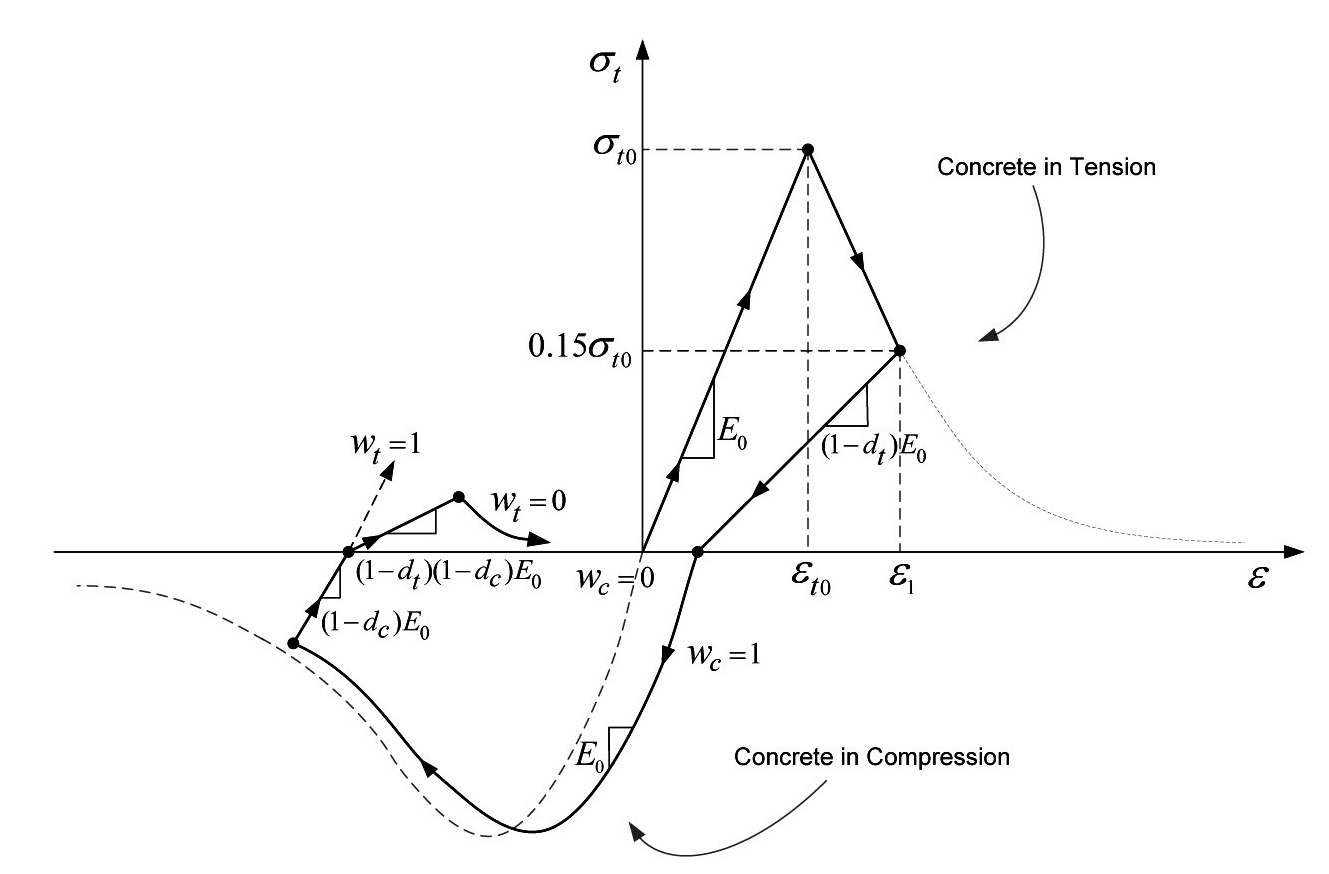
The constitutive behavior of concrete is modeled using a three-dimensional continuum, plasticity based damage model [20]. The concrete damaged plasticity model is efficiently capable of modeling concrete in all types of elements like beams, trusses, shells and in present case, especially solids. Inelastic behavior of concrete is depicted using the concept of isotropic damaged elasticity along with the isotropic tensile and compressive plasticity [21-25]. The formula suggested by Carreira and Chu [26] is adopted to calculate the compression strain curve of concrete.

where
γ = [f'c/32.4]3+ 1.55
The strain
Moreover, figure 1 explains the cyclic response of concrete with the load transition phenomenon. Initially, the material behaves linearly up to the tensile failure stress
E=(1-dt)E0
Upon load reversal, the recovery factors
2.1.2 Steel Constitutive Model
If the material modeling is incorrect, the calculation results of the static and dynamic structural response cannot be measured correctly [27]. For the better prediction of inelastic hysteresis behavior of steel, it is required to use such a material model that can properly simulate the cyclic behavior of the steel. Under load reversals, the load-bearing capacity of the steel member decreases as the number of load cycles increase [28].
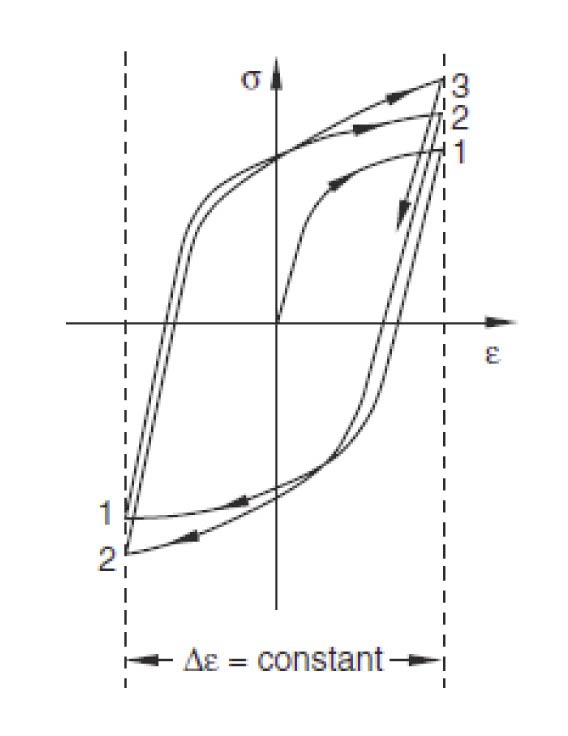
A collective steel constitutive model for structural steel found in literature [27-30] is used for cyclic behavior of steel. The cyclic response of steel under strain-controlled loading schemes is shown in Figure 2. To account for progressive hardening and softening effects [31], the steel is assumed to have the bilinear kinematic hardening behavior; i.e. yielding of the steel is independent of the equivalent stress, the center of the yield surface moves in
the stress space along with the expansion and contraction of the yield surface range. Although along with the kinematic hardening, some isotropic effects in hardening are also considered to account for the Bauschinger effect. This effect shows a reduction in the yield stress upon load reversal in the direction of plastic deformation, which has initially occurred. Kojic [30] demonstrates the process as; the yield stress due to deformation in compression is smaller than the yield stress previously achieved in tension. The similar behavior is noticed if the material is compressed first. This is due to the reverse propagation of the load cycle. The linear kinematic hardening component controls the effect while a nonlinear component improves the shape of the cycles [20]. The model is quite efficient to simulate the inelastic behavior of structural steel subjected to cyclic actions [28]. The input data is considered in correspondence to the tensile test results [18] of steel specimens discussed in later sections, to perceive more realistic behavior.
As the steel and concrete surfaces were directly adjoined in the test setup so the contact analysis procedure is developed in the FE model to simulate the experimental condition. The contact interaction option in ABAQUS is used in modeling the contact between steel and concrete in the composite shear wall by providing the geometric and mechanical properties for the interaction. First, the mechanical properties are specified and then associated with geometric features of the interaction to complete the contact assignment process. The mechanical property defined here, relates with the normal and tangential behavior. The values were assigned as default which gives rise to relatively rigid contact condition.
The ‘penalty algorithm option’ is used to define the normal behavior of the bond/contact. The default penalty stiffness with the scale factor of 0.1 is used in this manner to simulate the sticking characteristics of the interface. The ‘hard’ contact option is chosen as the pressure-over closure relationship to minimize the penetration of the slave surfaces into master ones at constraint points. It does not permit the transmission of contact pressure as long as the slave and master surface nodes do not come in contact [20]. Furthermore, the surfaces of the two bodies are not allowed to separate in order to overcome the convergence problems and to reduce the computational time. Coulomb friction model is used to simulate the tangential behavior of the contact interaction. The software calculates the shear force between surfaces using friction coefficient and contact pressure, which are specified as ‘frictionless and hard’, respectively. The steel and concrete web are joined with the steel flange at both ends using ‘tie constraint’ option so that the steel flanges connected with composite web can act as unit. This avoids the complications up to some extent in the interaction behavior of rest of the steel concrete interfaces during application of the load.
Geometric property corresponds to the selection of adequate contact discretization technique and choice of proper master and slave surfaces involved in the interaction. The surface-to-surface discretization is used to define the contact pairs constituting the master and slave surfaces. It facilitates the bond by considering the shape of two of the respective surfaces in the constraint region. The nodes are carefully adjusted to avoid penetration of some master nodes into slave nodes. Finally, to account for real sliding in steel-concrete interfaces of composite shear wall, smallsliding approach is used for the surfaces. Further, steel plates in the flange cross sections of the shear wall are modeled as embedded regions in the concrete by using ‘embedded constraint’ option in the interaction module. Although the steel plates introduced into the flanges are expected to contribute for the overall deformation capacity of the wall. However, this technique is utilized to emphasize more on the interface behavior of externally connected steel plates rather than the embedded one.
2.3 Element, Loading and Boundary Conditions
In the modeling of concrete core and steel plates skinned at concrete surfaces in the web and flange, solid element is chosen. In general, second-order solid elements are more efficient for complex geometric and stressdisplacement modeling but contact pressure calculations between contact bodies may be erroneous [32]. In a reduced integration analysis procedure, first-order element acquires potentially stiffer behavior with a slow convergence rate, preventing mesh locking and complexity. Hence, an incorporated reduced integration with the first-order 3D 8-node solid element (C3D8R) is used for steel and concrete contact surfaces to overcome the possible errors and to consider the cracks in tension and crippling in compression under cyclic loading. Such elements require a denser mesh for efficient and precise geometric simulations. However, while using reduced integration the model gets inherently stiffer, the tension stiffening parameters are required to be adjusted to match true experimental values [13,33].
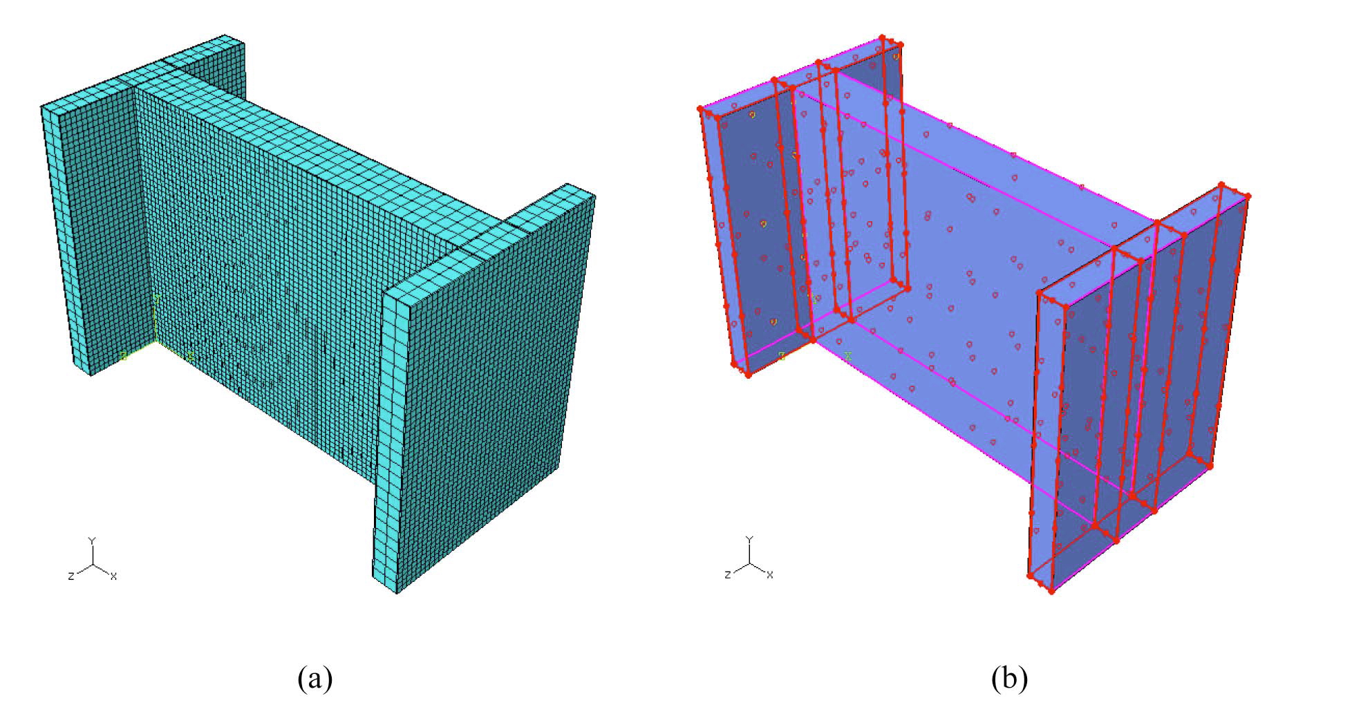
The numerical model under observation is fixed at the bottom to restrain each component of the shear wall in all degrees of freedom and to reflect the characteristics of the prototype. Load is simulated by applying the displacement control scheme rather than direct loading to generate cyclic behavior of the composite steel-concrete shear wall. A step-by-step procedure increasing the displacement to achieve the maximum deformation capacity of the model is used. For this purpose, a roller type boundary condition is applied on the top surface to prescribe the imposed displacements. To facilitate the proper simulation of the steel-concrete contact, the loading is managed to apply majorly on the concrete surfaces. The jumps in the displacement are applied by defining smooth ‘amplitude’ which reflects the total history data. The hexahedral finite element meshes and the interface configurations of the simulated shear walls are shown in Figure 3.
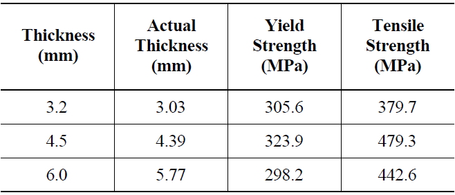
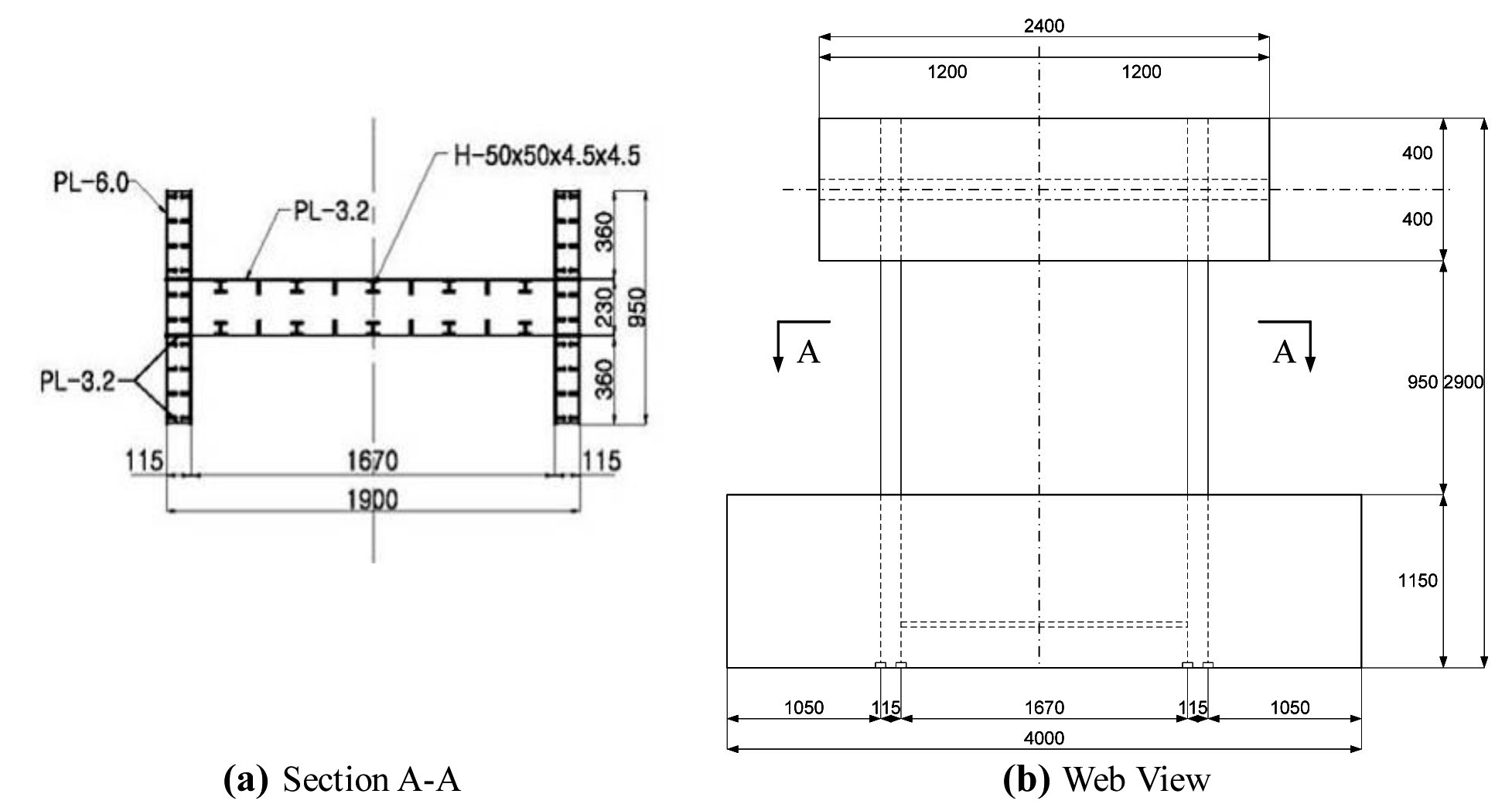
Four identical I-shaped composite steel-concrete shear wall (CSCSW) specimens subjected to reverse cyclic loading were tested. Each specimen consists of a hybrid web and two flanges at its ends, supported by 1150 mm thick base slab. Horizontal displacement controlled loading to the shear walls was applied through 800 mm thick concrete slab over the top, acting as a boundary condition. Both base and top slabs have the plan dimensions of 4000 mm x 1500 mm and 2400 mm x 1500 mm, respectively. Moreover, steel plates were embedded in the flanges to strengthen the concrete. All the experimental models were geometrically symmetrical; besides, thickness of concrete was kept same in all test specimens. The only geometric variable was the steel thickness provided in the flanges of specimens CSCSW-1, 2 and 3 whereas web steel thickness was changed in the specimen CSCSW-4 as an expectance to notice the effect. The type of reversed
[Table 1.] Thickness of Structural Components used.
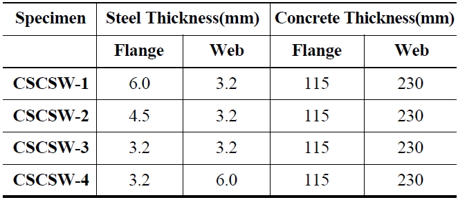
Thickness of Structural Components used.
cyclic lateral displacement can be considered as another variable because ultimate and failure values were supposed to be different based on deformation capacities of the test models. Table 1 shows the associated thickness of the structural components and other geometric details of the test specimen are shown in Figure 4.
The standard strength tests were performed to grasp practical deformation behaviors of both steel and concrete. The strength properties of structural steel were obtained from the tensile test and the cylinder compression test showed the 28 days compressive strength of different concrete specimens in Table 2 and Table 3, respectively. These test results helped in depicting the strength and deformation characteristics of steel and concrete and to generate the simulation input properties of both materials as well.
Since no standard reversed cyclic test procedure is available for testing composite steel-concrete shear walls, the lateral load was applied at a quasi-static rate in displacement controlled cycles considering cracking, yielding and ultimate state as the major states. All test specimens were incrementally loaded using a hydraulic actuator. The load cells were used to calculate the reactions. Linear transducers and strain gauges were placed in the middle top of the web to monitor the in-plane horizontal displacement and sequence of the yielding process. Initially, the process starts with slow loading and complete unloading. Subsequently, the test walls were subjected to high loads until the ultimate deformation capacity and failure point could be attained. At each incremental loading state, a constant load was maintained for a few seconds in order to measure and record the load, displacement response of the composite shear walls.
[Table 2.] Tensile Test Results of Steel

Tensile Test Results of Steel
[Table 3.] Cylinder Compression Test Results of Concrete
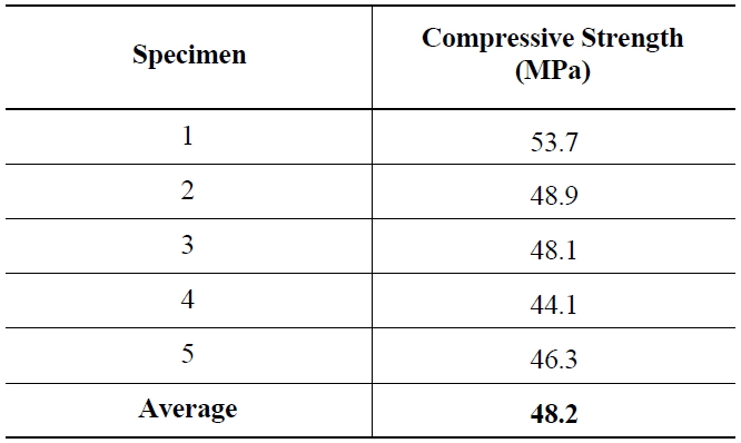
Cylinder Compression Test Results of Concrete
The finite element analyses give comprehensive picture of the overall load deformation behavior of the simulated composite shear walls from elastic to ultimate load. The lateral displacements and reactions are noticed at a particular node on the middle top of all the shear walls to depict the proportioned response. However, the comparative numerical load-displacement envelope/skeleton curves, the cyclic behavior of numerical models and prototypes, maximum and ultimate load concurrence with the test results reported by Lee [18] are primarily discussed in this section.
The numerical studies are performed to predict the nonlinear behavior, structural response and load-bearing capacity of the composite steel?concrete shear walls. Those results will later be compared with the experimental values. The results from the numerical analysis are the values of the displacements, the maximum and ultimate exhibited loads. The hysteretic loops and the overall skeleton curves are used to present and validate the outcomes.
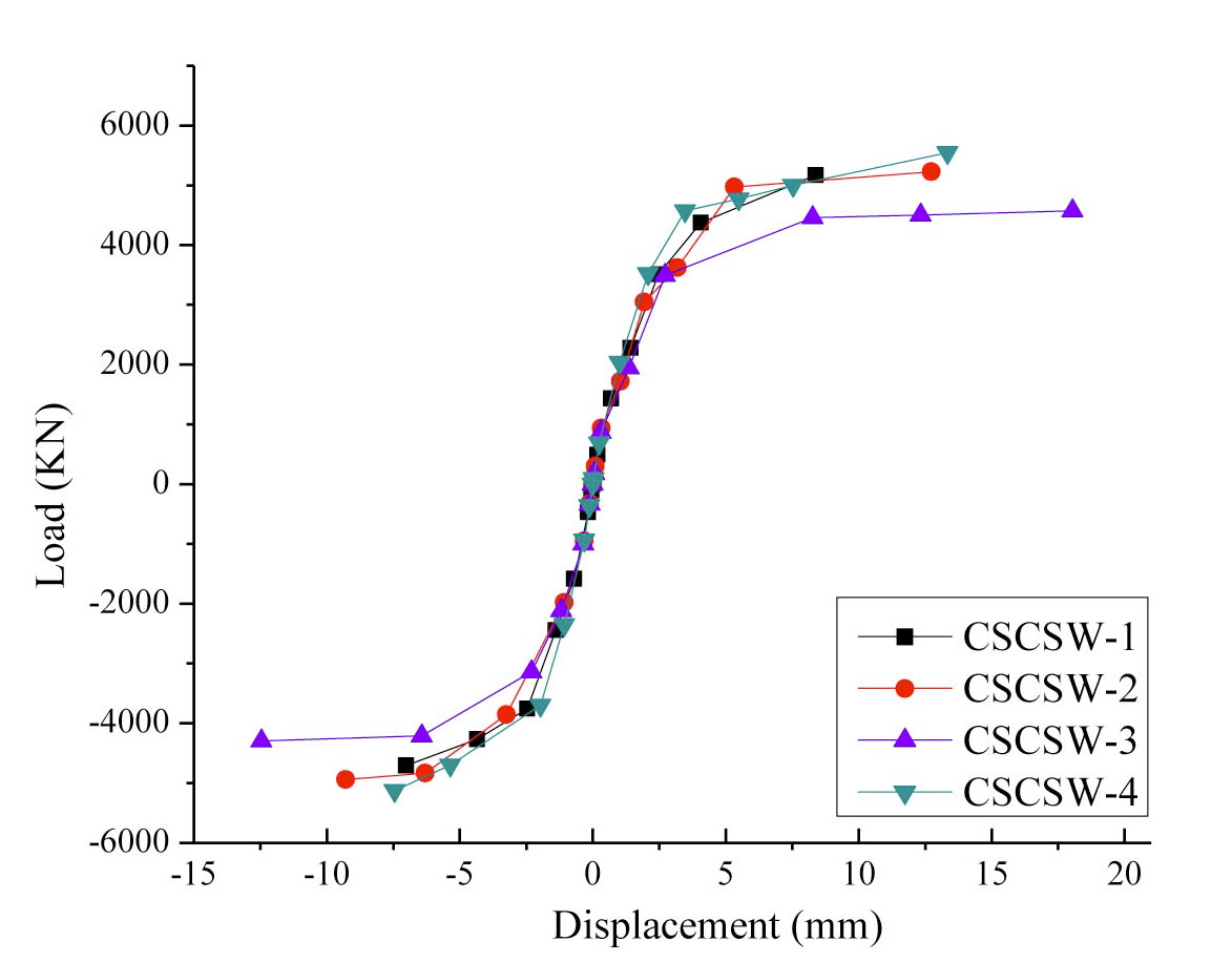
The specimens (CSCSW-1 to 4) with the difference in the steel thickness show quite similar deflection behavior. The comparisons between the horizontal loads (P) versus lateral displacement (Δ) envelope curves obtained from the finite element analysis are shown in Figure 5.
The varying deformation capacity of the shear wall numerical models can be clearly observed as the steel thickness is changed. The maximum resistance is offered by specimen CSCSW-1 with 6.0 mm and 3.2 mm thick steel plates provided in flange and web, respectively. The wall displaces not more than 7.5 mm and exhibits up to 5000 KN of approximate restoring load. Although the deformation trend is similar but the shear walls seem to
slightly lose the resistance as the steel thickness decreases from 6.0 mm to 4.5mm and further, if reduced to 3.2 mm in the flanged cross sections of the composite wall units, CSCSW-2 and 3 respectively. Moreover, the result comes out to be clearer if the greater amount of steel is provided in the web rather than the flanged parts. Accordingly, for specimen CSCSW-4 about 6.0 mm thick steel is compositely used with the concrete web whereas on either side, 3.2 mm thick steel is used in flanges. The provisions are truly converse to model CSCSW-1 but it is quite evident to observe the fact that the model show appreciable load bearing capacity which can be practically cost effective due to less use of steel in the web as compared to two flanges. Hence, the skeleton curves show better comparative structural behaviors of the simulated shear wall models. Next section presents the comparison of numerical results with the experimental results available in literature [18,19]. Moreover, the section below discusses the step by step comparative hysteretic cyclic behavior, overall skeleton behavior and compatibility of the numerical approach with the tested specimens.
4.2 Comparison with Experimental Data
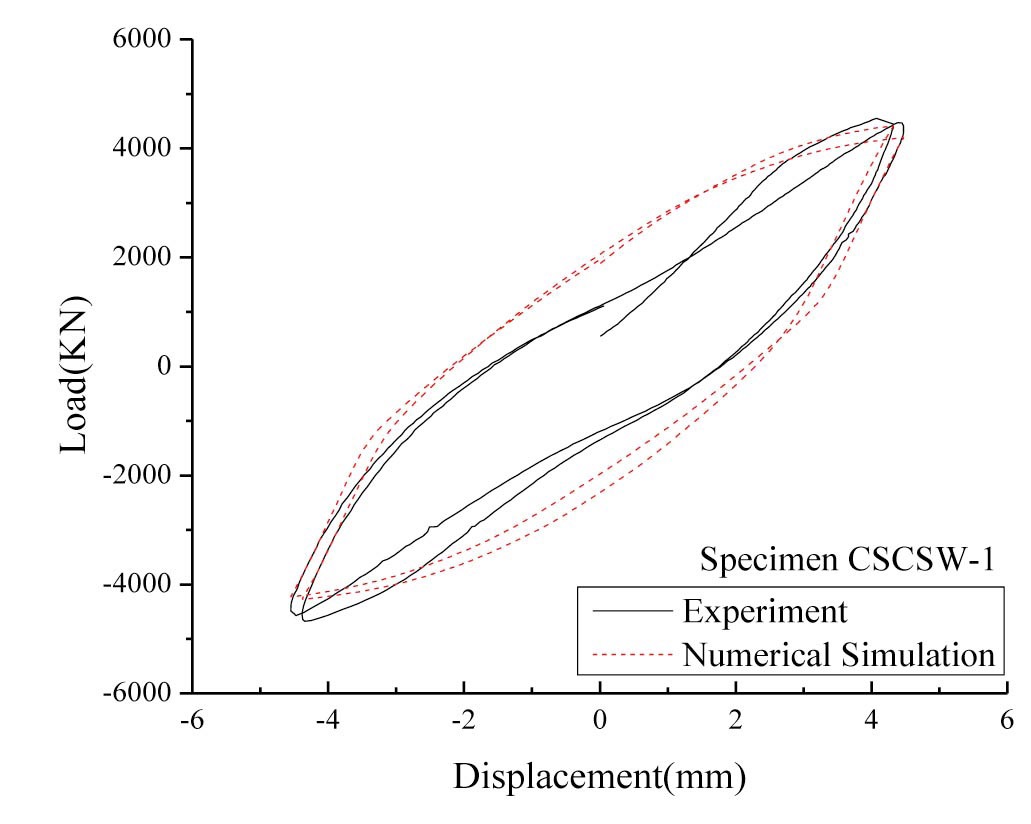
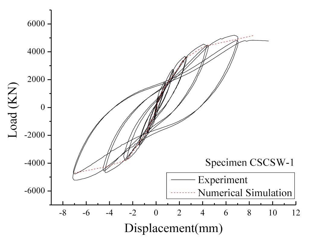
Figure 6(a) shows the hysteretic cyclic curves of the numerical simulation and the experiment under ultimate load cycle. As illustrated before, the structural deformation characteristics of all the specimens are observed to be similar, so specimen CSCSW-1 is generally considered for discussions.
The comparison between the numerical skeleton curves shown above, magnifies the stable behavior up to elastic limit. The experimental result lies within the boundary of numerically simulated curve with the nice effect of pinching and softening attributes. Whereas, the cyclic loop obtained from finite element analysis exhibits the softening mechanism upon load reversal but deprived of pinching
phenomenon. This is because of the ambiguities in the accurate modeling of the top support when the steel and concrete are connected which causes the complexity of the interaction. Another reason could be the difference in the assumed numerical bilinear behavior of the steel, from the actual behavior. Such situations had made the solid element unable to depict the required behavior. The bond behavior between steel and concrete is one of the prime aspects to control combined pinching. However, well predicted overall hysteretic response in terms of the skeleton curve is shown in Figure 6(b). The curve obtained by the simulation shows nice agreement of the cyclic response from elastic to ultimate load. The initial stiffness seems to be efficiently evaluated with a bit under-estimation of load values during ultimate and end load cycles but still can be accepted.
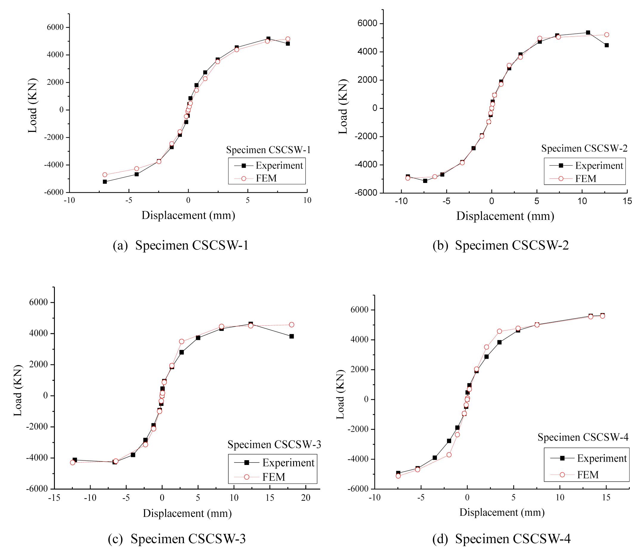
Based on the accuracy and concurrent nature of skeleton curves, all the shear wall models are validated with the experimental load-displacement envelope curves as shown in Figure 7. It may be noted that the uniaxial test results were used to generate the properties of steel of different thickness.
Figure 7 (a), (b), (c) & (d) shows the simulated results of specimen CSCSW-1, 2, 3 & 4 respectively, compared with the corresponding tested specimens. The finite element curves correspond well with the experimental data unless the behavior seems to be slightly under and over-calculated at some points. Comparatively, higher values are predicted by the numerical computations whereas the general behavior lies under the experimental envelopes.
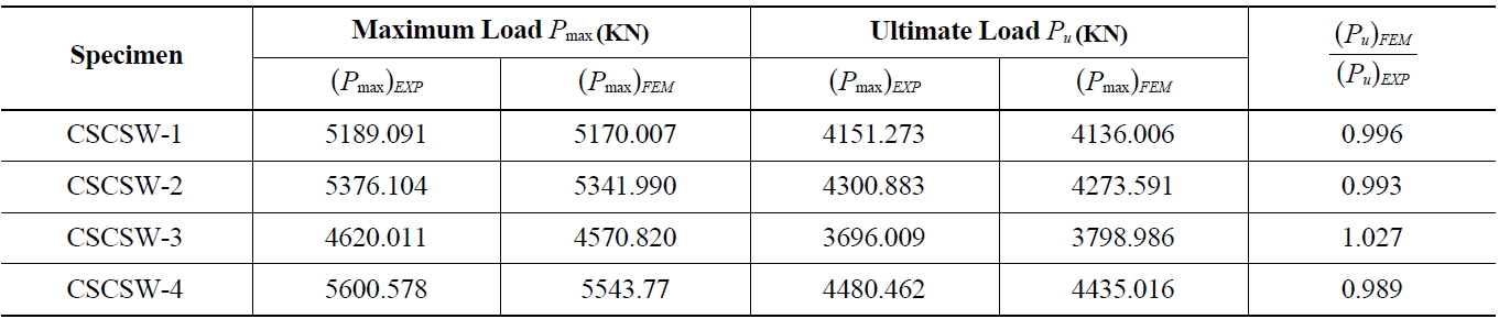
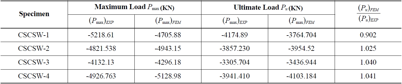
Tables 4 and 5 show the maximum and ultimate load values measured by experiment and predicted by finite element software ABAQUS, in tension and compression respectively. The ultimate strength is approximated as the 80 percent of the maximum load exhibited by the composite shear walls. The convergence of the numerical approach
[Table 4.] Comparison between Experimental & Numerical Strength Values in Tension

Comparison between Experimental & Numerical Strength Values in Tension
[Table 5.] Comparison between Experimental & Numerical Strength Values in Compression

Comparison between Experimental & Numerical Strength Values in Compression
was made sure by using Newton’s iterative method which involves an automatic load increment process. If the convergence was not achieved, the increment was minified by a certain prepossessed ratio. The solution was checked until convergence with the several repetition of process for the predefined number of iterations [20].
The present approach provides a practical way to model complex geometry of I-shaped steel-concrete composite shear walls of the nuclear power plants by using ABAQUS. This study has discussed the numerical and experimental attributes of the shear walls and presented parametric effects of the different steel thickness of the walls on the lateral resisting capacities.
The nonlinear cyclic behavior of the shear walls with steel-concrete acting together is investigated with reference to the earlier test data. The predicted load versus deformation curves, peak loads, ultimate strength values and deformation profiles are compared with the experimental results using skeleton curves to check the compatibility of the technique.
A good agreement is shown between the numerical and experimental skeleton curves as a response of reversed loadings. It is noticed that the deformation capacity of the shear walls rises with the increasing steel plate thickness, skinned at the concrete surfaces. Moreover, the use of steel in the web rather than the two flanges can lead to a costeffective solution for the lateral force resisting composite shear walls, as the approximately same deflection response has been observed in both cases. Although the shear walls are carefully modeled for simulation to get a response closed to experimental behavior, some differences have been seen amongst the results. Related to cyclic loop, lack of pinching effects is observed and discussed in comparison with the experimental hysteresis curve due to the heavy geometry, complex bond behavior of the walls, which generally cannot be depicted using the solid elements.


![Cyclic Behavior of Steel [20]](http://oak.go.kr/repository/journal/12583/OJRHBJ_2013_v45n1_89_f002.jpg)

![Geometric and Components Details of Test Specimen CSCSW-1 [18,19]](http://oak.go.kr/repository/journal/12583/OJRHBJ_2013_v45n1_89_f004.jpg)