Light guiding optical fibers have been widely employed in a variety of important applications, including sensors, communication systems, medical instrumentation, and many kinds of optical components. In particular, the field of fiber-optic sensors, along with the continuing research and development of optical fibers in the broad field of communications, has attracted considerable interest because optical fibers take many advantages from inherent properties such as superior sensing abilities, miniaturization feasibility, resistance to chemical corrosion, and robust immunity to electromagnetic interference (EMI). Since the early inventions of fiber-optic gyroscopes and acoustic sensors, a great deal of effort has been made to explore valuable sensing applications with benefits resulting from the innovation of advanced optical fiber technologies [1-5]. For example, intensity-based fiber sensors, fiber Bragg grating (FBG) sensors, coherence interferometric sensors, and Brillouin scattering distributed sensors have been investigated for accurate and reliable operation even in various harsh or hazardous areas ranging from chemical plants, nuclear power generation plants, oil reservoirs, aerospace, to bio-organisms.
Since these harsh environments are often encountered in practical applications, there are challenging demands for sophisticated optical waveguide sensors that can adequately work in the extreme physical conditions involving high temperature, high pressure, corrosion, toxicity, strong EMI, and nuclear radiation. Especially, in places where oil reservoirs are located far away from the Earth’s surface, temperature can reach 300℃ or higher. Also, temperatures in gas turbine engines or power generation systems can easily go over 1000℃ [6,7]. In these high-temperature harsh environments, conventional optical fibers exhibit the rapid diffusion of dopants from the central core to the cladding region. This changes the modal properties of the fiber and makes its implementation problematical for proper lightwave operation of sensing. However, novel breakthrough optical fibers, called photonic crystal fiber (PCF) or holey fiber, have been recently researched and demonstrated as various forms, opening the possibilities of numerous applications.
Holey fibers with periodic holes or PCFs can be produced by drawing an array of stacked capillary tubes in a hexagonal arrangement at a high temperature of tens of hundreds in degrees Celsius under surface tension forces. Meanwhile, random-hole optical fibers (RHOFs) are fabricated in a draw tower facility, by tapering the optical fiber preform, which consists of a very pure silica rod with the diameter of 2.0 or 3.5 mm for the core and a glass tube normally with the inside diameter of 9.0 mm and the outside diameter of 15.0 mm, packed with a silica powder mixture capable of producing air holes in situ at about the same high temperature as for the PCF fabrication. Then the optical fibers are coated with a polymer material as protective layer. In this paper, structural and propagation characteristics of the RHOF will be explained briefly. Experimental investigations of the invented RHOF are performed for pressure sensor application. Remarkable results are obtained for the RHOF with desirable pressure sensitivity independent of temperature as is required for the harsh conditions such as those in oil reservoirs.
The formation of holes in the microstructure RHOF is unique in that these are randomly distributed in the cladding region during the fiber fabrication process. The RHOF is measured to have well over a thousand air holes with sizes ranging around from 7.5 μm down to the order of tens of nanometers [4]. Although the holes are not continuous along the fiber longitudinal direction and are random in size, location, and length of the hole tubules, there are a sufficient number of air holes to provide a radially consistent lowering of the refractive index around the central core region.
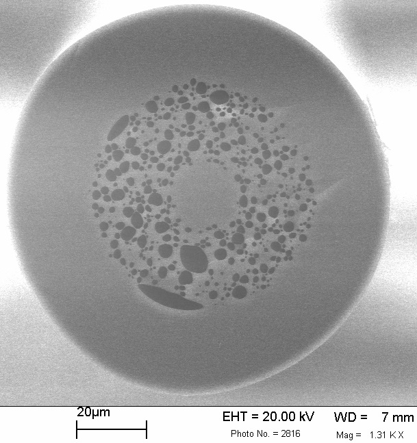
Figure 1 shows the scanning electron micrograph (SEM) picture of the cross section of a sample of a fabricated RHOF after removing the polymer coating. Compared with the photonic bandgap effect of the PCF, the RHOF does clearly exhibit the confinement of optical power due to the difference between the core refractive index and the average cladding index, and here provide multimode guiding, particularly in the near-infrared spectrum regions [4].
Since the RHOF is composed of only two different materials of pure silica and air, a distinction between the two can be made based on the cross-sectional SEM micrograph as of Fig. 1. The dark regions between the central core and the outer solid cladding are air holes, one of which is indicated in Fig. 1. It is noted that the diameter of the fiber core region is about 19 μm and its outer one is about 110 μm excluding the coating. And the space where the large and small pores are randomly distributed between the solid central core region and the solid outer tube region is designated as the pore band.
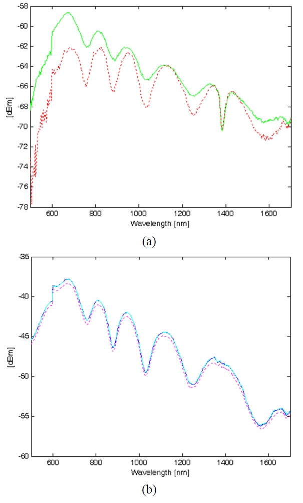
By using the multimode feature of the fabricated fibers, transmission measurements utilizing a white light as input signal and an optical spectrum analyzer (OSA) as detector have been performed. The RHOF is carefully connected to the white light source and OSA to ensure accuracy of measurements. The solid green line in Fig. 2(a) illustrates variations of the received power versus wavelength. It is noticed that there are six intensity peaks in the 600-1600 nm wavelength range. These peaks are part of the characteristics of the white light source and are not caused by the holey fiber. The dip around 1350 nm is attributed to the well-known OH absorption.
In the next step, a cubical 10-kg object is placed on the holey fiber and the transmission spectrum is measured. The dotted red line shows the intensity spectrum of the loaded RHOF. Again, six peaks are observed as in the previous experiment (solid green curve). Comparison of the two spectra reveals an interesting feature; namely, that the signal is attenuated under the load condition, with the largest attenuation occurring around 700 nm by more than 3 dB. This loss is due to the fact that when the fiber is compressed by the object, the signal is not tightly confined resulting from the close adherence of the glass material in the pore band and experiences microbending losses [8-10]. This phenomenon may be exploited in making pressure sensors with this type of holey fibers [11-15].
In order to better appreciate the properties of the RHOF, a very similar experiment was performed on a conventional multimode fiber. Fig. 2(b) shows the transmission spectra for this measurement. In this figure, the solid blue and dotted
pink curves correspond to no load and 10-kg load cases, respectively. The dashed cyan curve shows the transmission spectrum after removing the 10-kg load from the fiber for a repeatability check [15]. It is noticed that there is a very small intensity change over the entire scanned wavelength range. Also, it is worth noting that there are five intensity peaks instead of six in the 600-1600 nm wavelength range. This results from the fact that the dip around 1350 nm does not happen, as the multimode fiber used in this experiment was deliberately manufactured to minimize the OH absorption. Without this dip, two peaks merge into one and only five peaks are observed.
For the purposes of applications as pressure sensor in real situations, it is required that optical fibers should be sensitive to pressure but be insensitive to other physical quantities such as temperature [15]. If a sensor responds to two parameters like pressure and temperature at the same time, it is difficult to separate the effect of individual parameters. Considering the harsh environment sensing applications, the RHOF is proposed to be applied as a pressure sensor with temperature insensitivity. The conventional step-index
or graded-index fibers have dopants such as germanium in the central core region, which precludes the fiber from high temperature applications by the rapid diffusion of germanium. However, the RHOF does not contain any dopant material as it consists of only pure silica, making it suitable for pressure sensing in high-temperature environments. In addition, because the holey fiber has small air holes running inside, force from outside of the fiber will change light propagation. Thus, signal from the output of a holey fiber will be changed. Based on this idea, the RHOF is applied as an intensity-based pressure sensor.
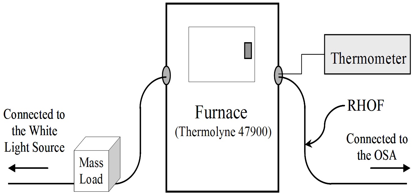
As an extension of the experiment for the temperature insensitivity, another section of the holey fiber about 2-meter long was inserted in a Thermolyne 47900, which is a furnace providing temperatures as high as 1000℃. To ensure that the heat inside of the furnace reaches the surface of the cladding of the holey fiber, a process of burning out the coating was preceded. Then, one end of the holey fiber, after cleaving carefully to get a clean and flat end face, is connected to the white light source. And the other end is connected to the OSA. Fig. 3 portrays the layout of an experimental research setup for the pressure and temperature sensitivity measurements. Since the light signal from the source goes through a mass-loaded section and a furnace-enclosed section of the RHOF, we can measure the pressure sensitivity and the temperature sensitivity at the same time.
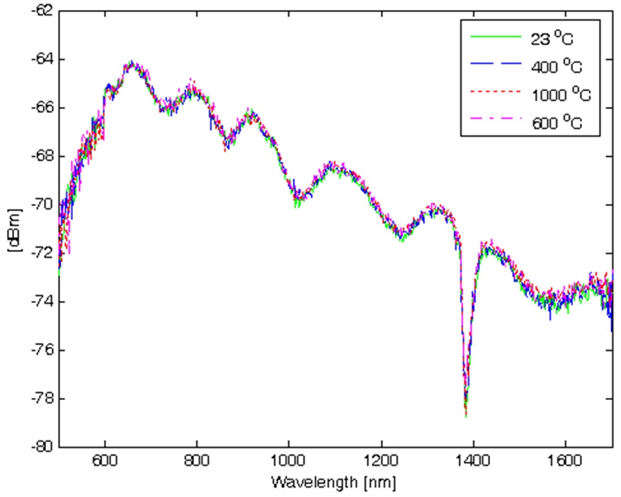
Figure 4 shows spectra over the wavelength range between
500 nm and 1700 nm at different temperatures up to 1000℃. First, temperature starts from 23℃ (room temperature). The solid green line represents the light signal spectrum at one end. The dashed blue line represents the spectrum at 400℃. And the dotted red line represents the spectrum at 1000℃. Then, the furnace was cooled down. Of this half cycle, the spectrum at 600℃ is scanned, which is plotted as the dash-dotted pink line. Finally, the spectrum at 32℃ after one cycle of temperature change is also measured without much variation. That is, it is noticed that there is almost no dependency of the holey fiber on the temperature variation up to 1000℃ ― less than 0.3-dBm variations in the wavelength range between 600 nm and 1500 nm. This might go to even higher temperature, although this was not tested because of the furnace limitation.
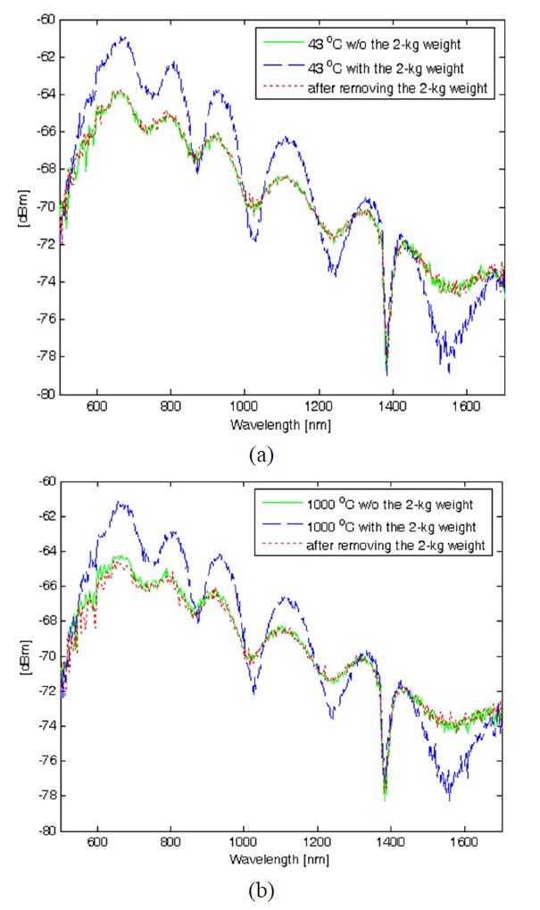
To ensure that this RHOF with temperature insensitivity has pressure sensitivity, a cubical 2-kg weight was put on some section of the holey fiber outside the furnace, as shown in Fig. 3. At 43℃, Fig. 5(a) shows how well the fiber responds to pressure. The solid green line represents the output spectrum when no weight is put on the fiber. And the dashed blue line represents the output spectrum when the mass of the 2-kg weight is put on the fiber. About 3-dB difference is noticed at 670-nm wavelength. Then, the output spectrum, after the weight is removed, is scanned as the dotted red line. Clearly, it is shown that the fiber does not have any hysteresis in this test. The same experiment is repeated after increasing the furnace temperature to 1000℃. And about the same performance ― about 3-dB difference at 670-nm wavelength and no hysteresis is observed as shown in Fig. 5(b). One thing we can notice here is that the intensity, when a weight is on a section of a holey fiber, is increased, which is different from the result in Fig. 2(a). The reason is that the section used here is different from the one in the previous measurement. Due to the structural difference, the intensity response is different. And still the temperature-insensitive pressure sensitivity is well observed.
Based on the results in Figs. 4 and 5, it is observed that the values of the pressure sensitivity are about 1.55, 1.45, and 0.9 dBm/kg at the operation wavelengths of 670, 810, and 920 nm, respectively. It is also noted that the same experiment with the mass loading and the temperature increasing from the room temperature up to 1000℃ has been repeated three times, indicating that the RHOF provides good pressure-sensing repeatability with the temperature insensitivity. At this time, the measurement of the RHOF has shown good performance, ranging from no load to 10-kg weight for the pressure sensitivity and from 23℃ to 1000℃ without any significant artifact. Overall from this inventive test work, it is clearly expected that the wider operation range of the optical fiber can be improved with the stronger material composition, because the pressure sensitivity independent of temperature comes from the structural characteristics of the porous RHOF.
By tapering the optical fiber preform packed with a silica powder mixture capable of producing air holes in situ, RHOFs are fabricated in a draw tower facility and applied to pressure detection with temperature insensitivity. Compared to the small intensity change over the scanned wavelength range from 600 nm to 1600 nm, the 10-kg loaded RHOF shows the largest attenuation occurring around 700 nm by more than 3 dB. Generally, this loss is due to the fact that when the fiber is compressed by the object, the signal is not tightly confined resulting from the close adherence of the glass material in the pore band and experiences microbending losses. When the 2-kg weight is put on some section of the fiber through the furnace with increased temperature as high as 1000℃, about 3-dB intensity difference is noticed at 670-nm wavelength without any hysteresis. This means the repeatability is excellent, which makes the porous RHOF very desirable as a pressure sensor with temperature insensitivity.