The head mounted display (HMD) is a display device, worn on the head or as part of a helmet that has a small display optic in front of one or both eyes. HMDs have been used in a wide range of virtual reality and augmented reality applications [1-3]. High performance HMDs should be easy to operate and allow simple installation in any platform. An HMD consists of two optical parts, namely as couple-in part and couple-out part. The couple-in part magnifies the micro-display image and the couple-out part projects the magnified image to the observers. Because a range of optical elements are embedded in limited space to display a virtual image, reducing size of the entire volume is an important issue.
A holographic optical element (HOE) can be a solution. It is a diffraction grating that can be used as a mirror, lens and directional diffuser in many display systems [4,5]. T. Ando et al. proposed a HMD that was fabricated using HOEs [6]. However, this method had limited size reduction because they did not use waveguide-type HMD. Y. Amitai et al. and I. Kasai et al. reported an eye display using a volume hologram or grating [7] as the optical combiner in front of the eyes on a waveguide [8,9], which could minimize the size of the optics. However, this method did not yield high diffraction efficiency, and previous studies did not fabricate full color HOE. Subsequently, full color eyewear display was proposed by H. Mukawa et al. [10]. In this method, the issue of color-uniformity should be solved.
To overcome the abovementioned problems, this paper proposes a reflection-type HOE with high diffraction efficiency for a waveguide-type HMD using a photopolymer. A photopolymer is one of the hologram recording materials that has high diffraction efficiency and low cost. Furthermore, it does not require any chemical or wet processing after recording the holograms. Because of such advantages, the photopolymer has been used widely in several research fields, which include optical elements [11,12], holographic storage [13], holographic display [14] etc. The characteristics of the photopolymer are reported elsewhere [15] but this study was limited to the monochromatic only.
This paper extends the previous work to full color HOE analysis. The asymmetric geometry of the reflection gratings in the photopolymer was also analyzed. The unique point in this method is the use of a full color HOEs instead of the conventional couple-in and couple-out optics used in conventional HMD systems. This paper presents a laminatedstructure method for fabricating full color HOE. The results showed that the proposed method can capture high-quality color images successfully.
II. HOE FOR THE WAVEGUIDE-TYPE HMD
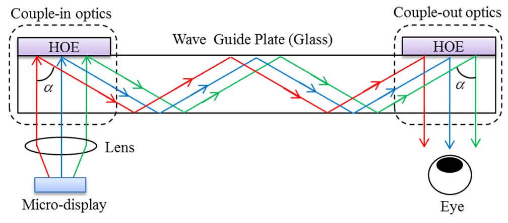
Figure 1 presents a block diagram of the HOE for a waveguide type HMD. In the proposed method, the HOEs act as diffractive elements to guide the light in certain angles. Thus, the plane wave from the lens is diffracted by the first HOE, and propagated by the total internal reflection inside the wave guide plate.
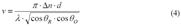
As shown in Fig. 1, the diffraction angle of the image ray is
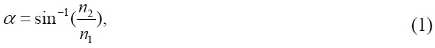
where
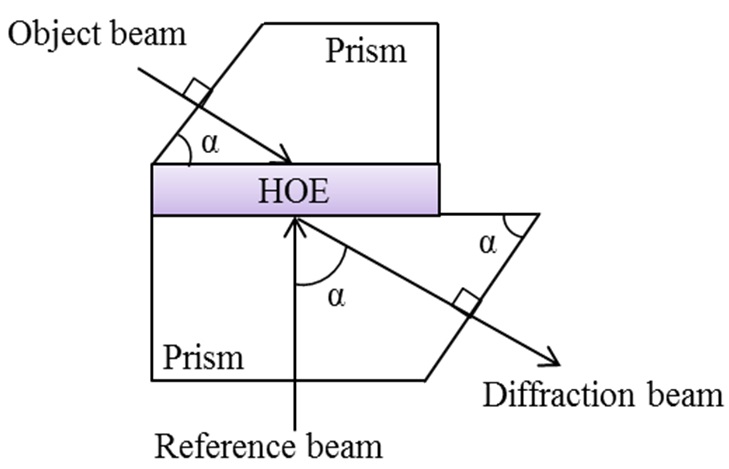
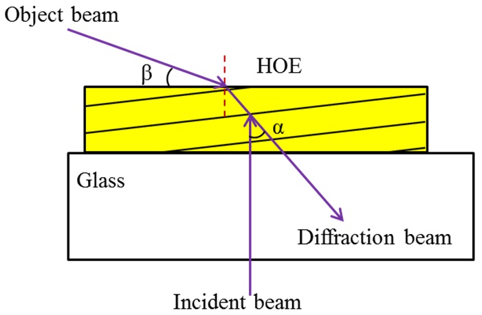
According to the manner of fabrication, the HOE can be classified into two types, one is the reflection-type and the other one is the transmission-type. Recently, several studies based on reflection holography have been reported [16]. The angular selectivity and wavelength selectivity of the reflection-type HOE are much wider than those of transmission type HOE. The reflection-type HOE can transmit the visible rays and reflect the band of specific wavelength of rays. Therefore, it is advantageous to use the reflectiontype in the proposed method, which is fabricated by exposing two wave fronts opposite to each other. In addition, the HOE is recorded with an asymmetrical grating structure. The incident beam is perpendicular to the material, as shown in Fig. 2, to reduce the light loss caused by the surface reflection. The angle of the object beam
In the process of fabricating HOE, the prisms are used to unify the different refractive index, as shown in Fig. 3, where the object and diffraction beam are guided by the prisms to make
III. OPTICAL CHARACTERISTICS OF THE PHOTOPOLYMER
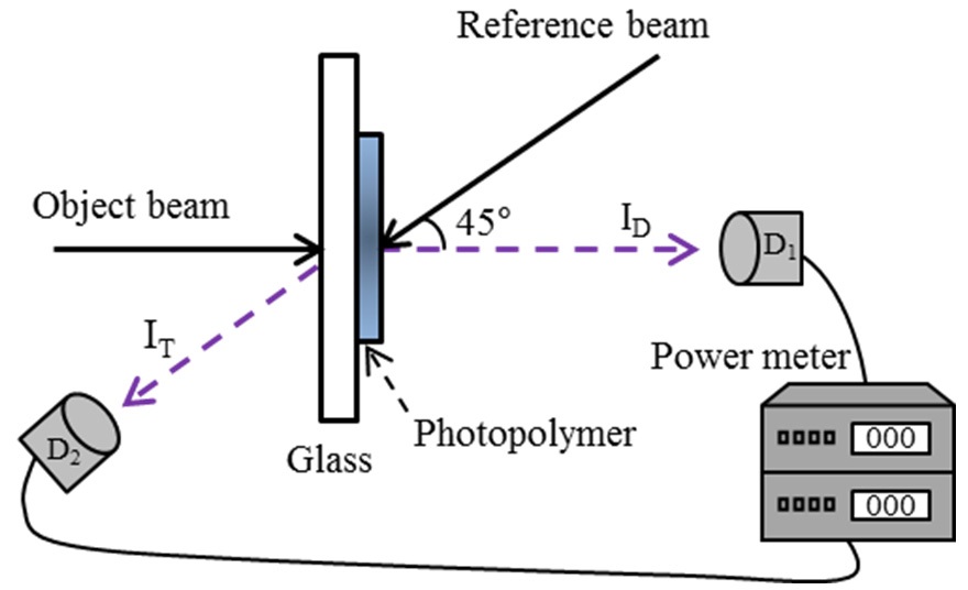
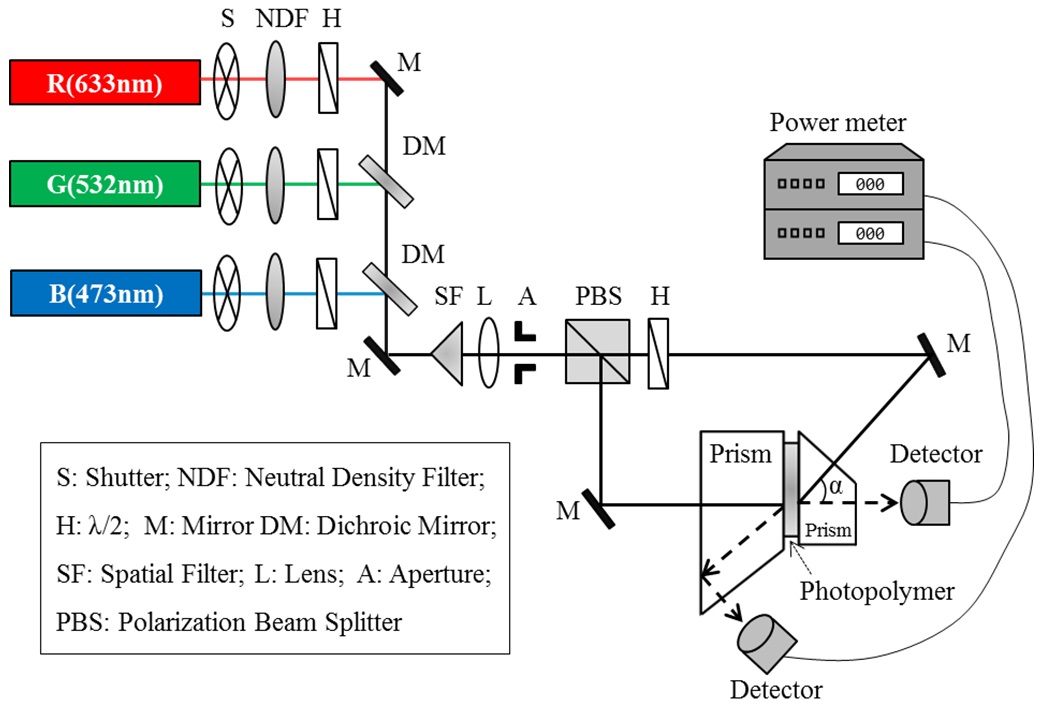
The characteristics of the recording material have significant effects on the many applications and the development of holography. To fabricate the proposed HOE, it is necessary to understand the optical characteristics of photopolymer. The diffraction efficiency of the photopolymer was measured using different exposure durations and different exposure energies. Fig. 4 presents a schematic diagram of the experimental setup. The reflection holographic gratings were recorded in asymmetric geometry in a photopolymer. To prevent the occurrence of the multi-spot by total internal reflection, the incident angle of the beam was set to 45°. The intensity of the diffraction beam and transmission beam were detected by the corresponding photo detectors, which are connected to the power meters.
The gratings were recorded at 633 nm (red), 532 nm (green) and 473 nm (blue), the diffraction efficiency
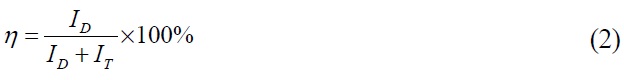
where,
and transmission beam, respectively.
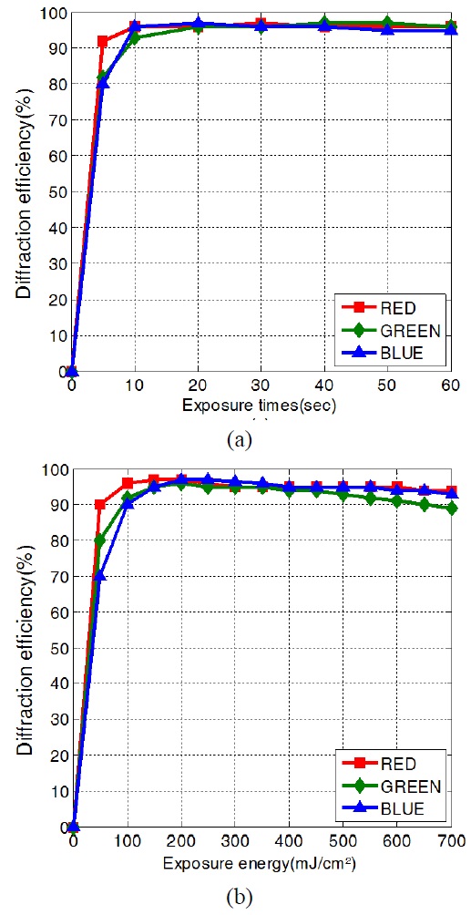
Figure 5 shows the experimental results corresponding to the different exposure durations and exposure energy for each color. The intensity of the two recording beams was set to
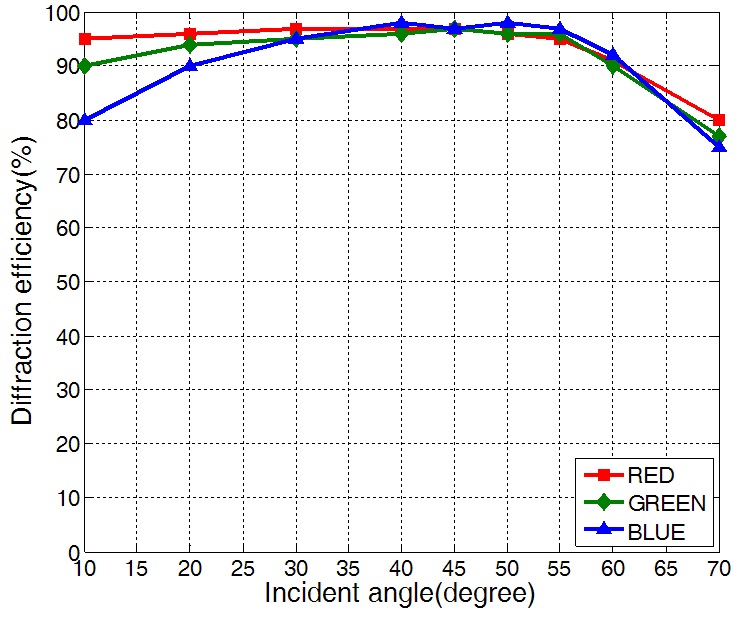
The diffraction efficiency of the photopolymer was also measured according to the incident angle. Several samples of the photopolymers were recorded at a range of incident angles from 10° to 70°. The exposure energies of the recording beams were set to 150 mJ/cm2, 150 mJ/cm2 and 200 mJ/cm2 for each R, G and B laser, respectively. Fig. 6 shows the maximum diffraction efficiencies of the samples as a function of the incident angle. From the results, the diffraction efficiencies of the photopolymer were more than 95% at the angles ranging from 30° to 55°.
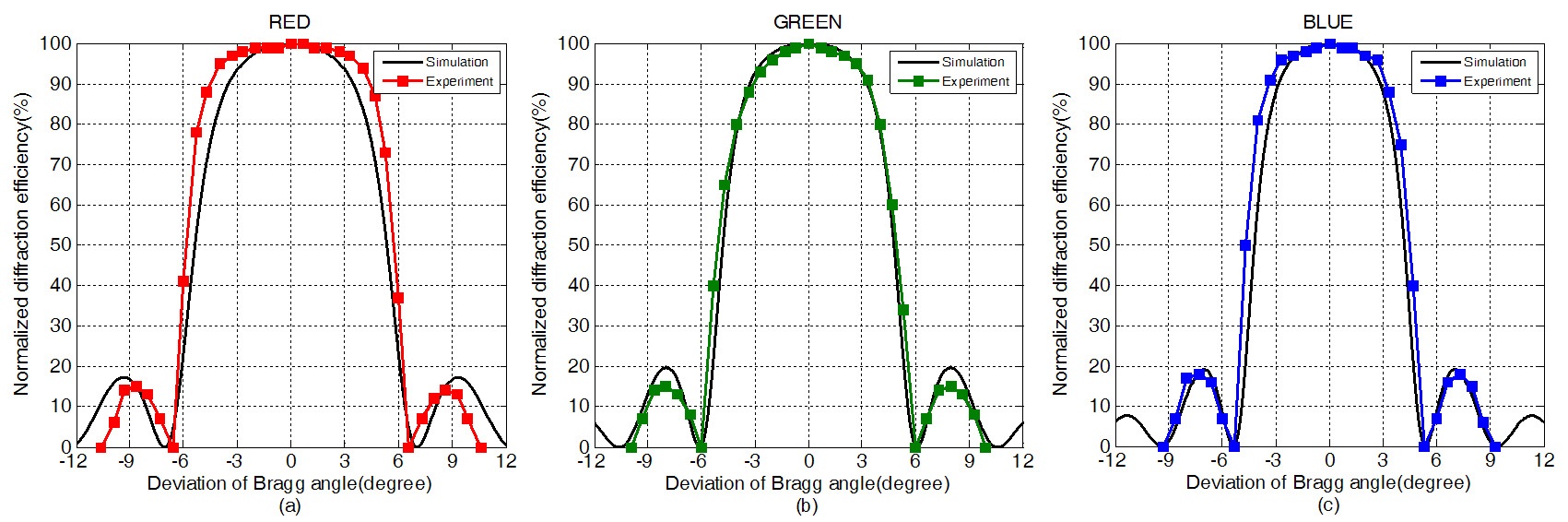
The diffraction efficiency
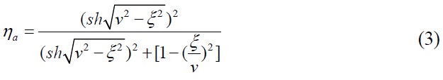
where
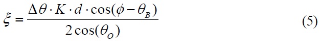
where
Bragg angle.
Figure 8 shows the experimental setup for recording a full color HOE. Three laser wavelengths, 633 nm (red), 532 nm (green), and 473 nm (blue), were selected. The laser beam used for recording was switched by the shutter placed in front of it. To adjust the intensity ratio of the reference beam and object beam for each R, G, and B laser, a half wave plate and polarization beam splitters were used, as shown in Fig. 8. In this arrangement three primary lasers with red, green, and blue wavelengths were combined using two dichroic mirrors. The beam intensity from the three lasers was adjusted by the corresponding neutral density filters, and the overall exposure energy was controlled by varying the exposure time.
As mentioned in section II, the diffraction angle or object angle should be
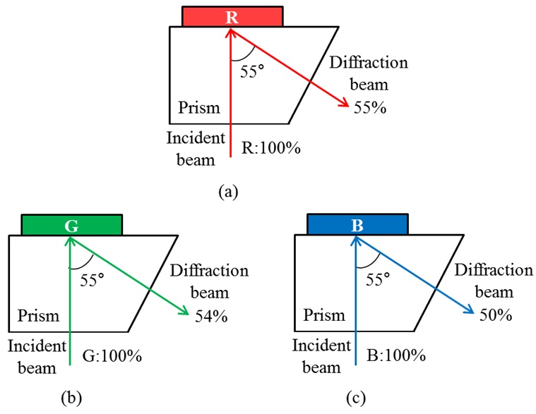
After recording the HOE, the efficiencies were measured. The efficiency is the intensity ratio between the incident and diffracted beam, which is the actual efficiency of the display. The efficiencies for the R, G and B color were 55%, 54% and 50%, respectively, as shown in Fig. 9. As
mentioned above, the prism is required in the recording process. On the other hand, the efficiency loss is caused by the reflection of the prism surface and the adhesive between the photopolymer and prism. By considering the absorption factor for the wavelengths are 15%, 25%, and 28%, respectively, the measured efficiencies can be considered to be similar to the high diffraction efficiency shown in section III.
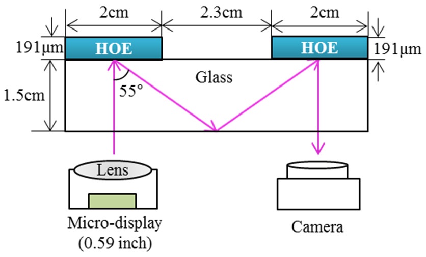
The scheme diagram of the experimental setup and all the specifications used in the experiment are shown as the Fig. 10.
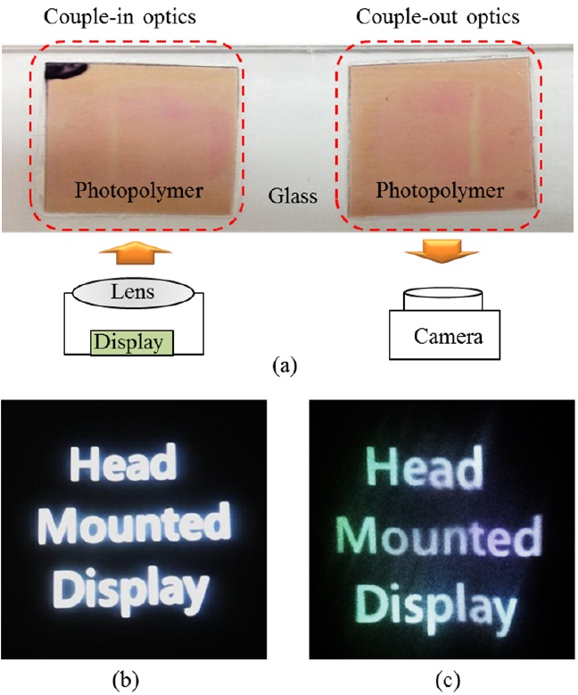
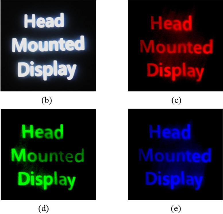
Figure 11 presents the experimental results using monochromatic HOEs for the HMD system. Fig. 11(a) shows the structure of the system, where two HOEs are used as the couple-in and couple-out optics. The image shown in Fig. 11(b) is the original image that is illuminated by a micro display to couple-in optics, and output images were captured according to each color HOE. The results are shown in Fig. 11(c), (d) and (e), respectively.
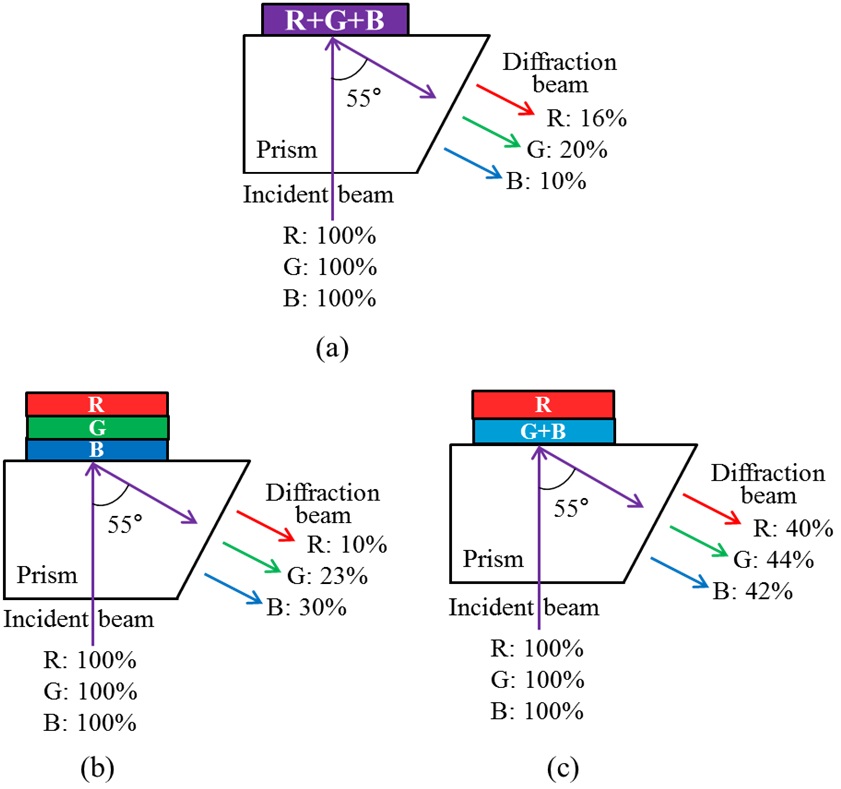
One of the most important points of the system is that it can provide full color images. This study evaluated the efficiency using three structures of the full color HOE. First, a HOE was recorded by simultaneously illuminating the three lasers in a single photopolymer as shown in Fig. 12(a), where the output efficiencies for R, G, and B were 16%, 20% and 10%, respectively. The second one is the laminated structure, which laminates three photopolymers, as shown in Fig. 12(b). In this case, the corresponding measured output efficiencies of R, G, and B were 10%, 23% and 30%, respectively. Obviously, the color HOE made using this method cannot be used in the HMD either because of the low efficiency and non-uniformity. Last one is a composite structure shown in Fig. 12(c). In this method, the two-layer photopolymers were laminated: a red color HOE and a HOE combined by a green and blue color. The corresponding output efficiencies of R, G and B, which were measured using this method, were 40%, 44% and 42%, respectively. As a result, much higher efficiency and more uniform distribution than the other methods were achieved. Note that, in the three layers laminated structure shown in Fig. 12, because the beam passes through two layers of photopolymer, obviously the most exterior one
will lose much of the beam intensity. For this reason, quality of the uniformity and efficiency will significantly decrease. Thus, we can expect that synthesizing the R, G, and B color in a single photopolymer can be an ideal solution. When simultaneously using three color lasers to record grating, however, inter-modulation will be occurred. Therefore, by comparing the results obtained by such methods, we eventually select the two-layer composited structure which is regarded as best one among the three types of structures to synthesize full color HOEs.
Figure 13 shows the experimental results for the full color HOEs. The experiment process was the same as that for monochromatic HOEs, which were fabricated using the proposed two-layer composited structure. From Fig. 13(c) the output image quality was as good as expected. This means that the full color HOE, which was fabricated by the photopolymers, can replace the conventional optical elements of the waveguide-type HMD system.
Full color HOE, which was fabricated using a photopolymer, was presented. The HOEs act as the couple-in and couple-out optics in the waveguide-type HMD. To implement the system, the optical characteristics of the photopolymer were analyzed using three lasers operated at 473, 532, and 633nm, respectively. The diffraction efficiencies of the photopolymer were more than 90% for each R, G and B color. In addition, it provides wide angular selectivity and can fabricate high quality full color HOEs. The experimental results also verified the output efficiencies of full color HOE; 40%, 44%, and 42% for R, G, and B color, respectively. This means that the system has good color uniformity and brightness performance. The proposed method can reduce the volume of the system. Furthermore, simplified fabrication and high diffraction efficiency are also advantages in this system. Future studies should examine issues of eye box, eye relief and field of view.