We present both theoretically and experimentally the thermo-optic characteristics of micro-structured optical fiber (MOF) filled with mixed liquid. The performance of MOF depends on the efficient interaction between the fundamental mode of the transmitted light wave and the tunable thermo-optic materials in the cladding. The numerical simulation indicates that the confinement loss of MOF presents higher temperature dependence with higher air-filling ratios d/Λ, longer incident wavelength and fewer air holes in the cladding. For the 4cm liquid-filled grapefruit MOF, we demonstrate from experiments that different proportions of solutions lead to tunable temperature sensitive ranges. The insertion loss and the extinction ratio are 3~4 dB and approximate 20 dB, respectively. The proposed liquid-filling MOF will be developed as thermo-optic sensor, attenuator or optical switch with the advantages of simple structure, compact configuration and easy fabrication.
Micro-structured optical fibers (MOFs) [1-2] have attracted considerable research interest in recent years due to their novel light guidance properties [3-4]. The micrometer- sized air holes running along the length of the fiber provide great freedom in optical waveguide design during the fabrication procedure [5-6]. Additionally, the infiltration of functional materials into claddings provides further responses under different external physical fields, leading to tunable propagation properties of MOFs for promising all-in-fiber optical components [7-8].
Compared with the mechanical counterpart, the waveguide devices based on liquid-filling MOFs [9] provide efficient control and modification of optical signals for the development of optical communication and sensing systems [10], leading to the advantages of low insertion loss, high sensitivity, performance stability and integrity. T. Larsen [11] first demonstrated a low-voltage controlled broadband optical switch infiltrated with liquid crystals, with the extinction ratio as much as 60 dB for a 0.4℃ temperature interval and insertion loss of 1 dB. Y. Yu and X. Li introduced a novel MOF temperature sensor based on liquid ethanol infiltrated into the cladding with the sensitivity of 0.315 dB/℃ [12]. Optical switches have been reported by Y. Wang and W. Jin based on fluid-filled MOF Bragg grating [13] or temperature-controlled hybrid micro-structured fiber [14], with the extinction ratio >30 dB via the temperature adjustment of ±5℃. They also investigated a thermo-optical switch based on the absorption of the filled fluid in combination with the interaction between the core mode and the excited “fluid rod” modes [15]. According to all the reports above, the cross section structure of MOFs is significant for the fabrication of optical components and needs systematical analysis with numerical simulation. Additionally, the temperature sensitivity range of the components is always constant and cannot be tunable in response to the exotic environment, which severely limits their practical application.
In this letter, we have demonstrated the thermo-optic characteristics of liquid-filling solid core MOFs, which exploits temperature dependence on the refractive index of mixture liquids incorporated into the cladding. Numerical simulation illustrates that the greater air-filling ratio, longer incident wavelength, and fewer air holes in the cladding could effectively enhance the performance of the device. For a 4-cm-long liquid-filling grapefruit MOF, with the different concentration of the two components (toluene and chloroform), it presents a tunable high temperature-sensitive range within 5℃. The insertion loss is about 3~4 dB and the extinction ratio is approximate 20 dB, respectively. As an intensitymodulated optical component, expensive and high precision apparatus such as broadband amplified spontaneous emission (ASE) fiber source and high-resolution optical spectrum analyzer (OSA) are not necessary. Such a device will be developed as a thermo-optic sensor, attenuator or slow response optical switch with the advantages of simple structure, high integration and easy fabrication with the lowest cost.
II. THEORETICAL ANALYSIS AND NUMERICAL SIMULATION
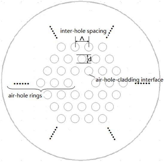
The interaction between the evanescent field and the cladding air voids makes the core mode very sensitive to any refractive index fluctuation at the air-hole-cladding interface (the boundary between the air holes in the cladding and the solid fiber core, as indicated in Fig. 1). Tunable
refractive index materials, such as temperature-sensitive mixture liquids (toluene and chloroform), could be introduced into the air holes and will modulate the guiding properties of MOFs. For the temperature behavior of the refractive index of the liquids, a linear approximate expression
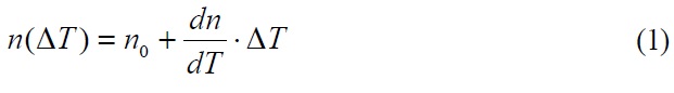
has been assumed, in which
Here,
To investigate the dependence of the propagation characteristics on the structure parameters, a series of MOFs with identical cladding configuration and inter-hole spacing (which means the distance between the centers of the adjacent air holes, taking

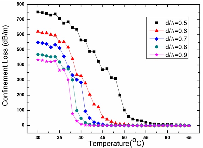
The results are shown in Fig. 2 in which the confinement losses are illustrated against the temperature with the airfilling
ratios
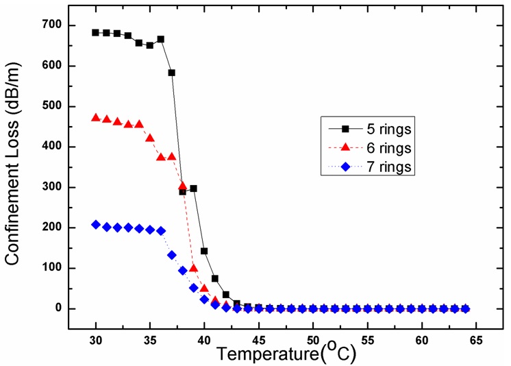
The functional relationship between the confinement loss and the temperature with different air-hole rings in the cladding has been shown in Fig. 3, in the condition that the incident wavelength of 1550nm and the air-filling ratio
the air-hole rings, which indicates that the extinction ratio and the temperature sensitivity of the device could be effectively intensified with fewer air-hole rings in the cladding.
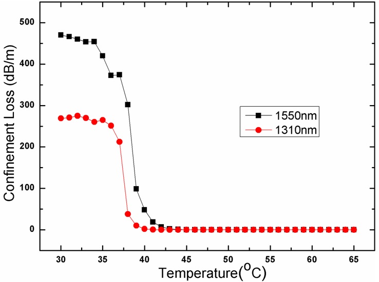
Figure 4 shows the confinement loss as functions of temperature at 1310nm and 1550nm for MOFs with 6-ring cladding air holes and
III. EXPERIMENTAL RESULT AND DISCUSSION
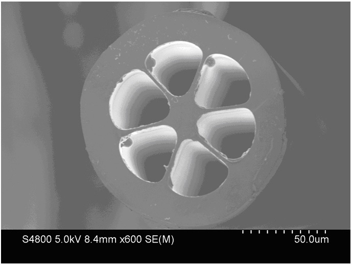
According to the numerical simulation above, the temperature sensitivity of MOFs filled with liquid mixtures of high thermo-optic coefficients presents increasing functional relationship for higher air-filling ratio and longer incident wavelength. Additionally, fewer air-hole rings could enlarge the extinction ratio of the device at the same time. Based on these conclusions, the high air-filling ratio grapefruit MOFs with 1-ring air hole in the cladding supplied by FiberHome Technologies Group are employed in the experimental system and the communication wavelength at 1550nm is considered as signal source. As shown in Fig. 5, the microstructured holey region is 87.3 um and the diameter of fiber core is about 12 um. The air holes with diameter of
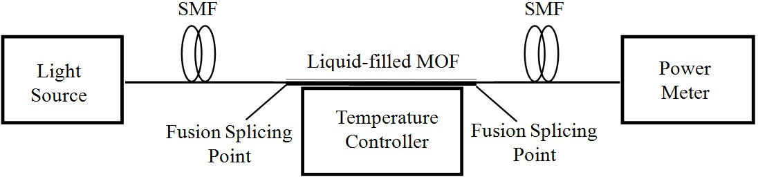
The configuration of the experimental setup for the thermooptic characteristic test has been shown in Fig. 6. All of the air holes of the grapefruit MOF are infiltrated with mixture liquids of toluene and chloroform simply by capillary action for several tens of seconds. The 4 cm-liquid-filled MOF is then spliced to standard single-mode fibers (SMF) with a splicing loss of 1.5 dB and placed into the temperature controller in the V-groove of an aluminous slab to avoid bending effects. The transmission powers of mixture liquid-filled MOF at different temperatures are measured as an intensity signal for investigating the temperaturedependent properties. The light source is a tunable semiconductor laser (Agilent 8164A) at the wavelength of 1550nm. The transmission power is measured by a digital power meter (LX Light Wave) and is recorded from 20℃ to 60℃ at 1℃ intervals. For the correction of the fluctuation of light source, the average values from multiple measurements are operated in the practical experiment, for about 10 times at each temperature.
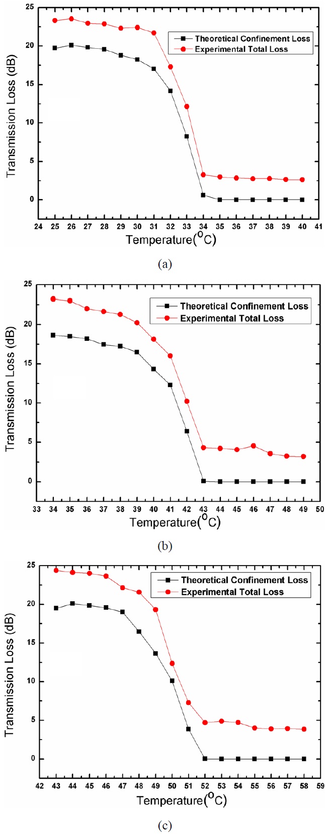
Figure 7(a) shows both the theoretical confinement loss and the experimental total loss at 1550nm for grapefruit MOF as a function of temperature from 25℃ to 40℃ with the volume ratio of toluene and chloroform as 7:3. The attenuation of the device varies from 23.3 dB to 2.6 dB within the temperature transition range of 5℃ (from 30℃ to 34℃), corresponding to the extinction ratio about 20.7 dB between the low and high transmission states. The obvious transmission jumping phenomenon could be considered as high temperature-sensitive region or optical switching effect. The simulated and experimental results present consistent variation trend. It should be noted that the total loss comprises not only confinement loss but also intrinsic loss
and splicing loss, so it is about 3 dB higher than the theoretical confinement loss.
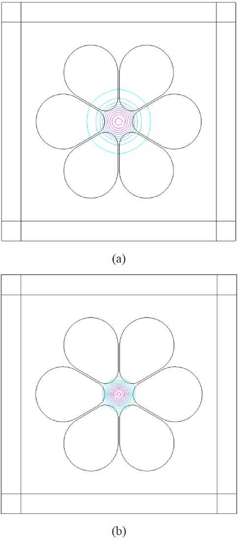
The physical mechanism of this phenomenon lies in the manipulation of the core mode by the spread of the evanescent mode field, which mainly depends on the distribution of the refractive index of the material infused in the air holes. If the refractive index of the material is lower than that of silica, the mode is confined in the core by total infernal reflection and only a small percentage of the optical field will penetrate into the cladding. In this case, the mode propagates through the fiber with minimal loss. On the other hand, if the refractive index of the material is close to or even higher than that of silica, the mode field will refract into the high index medium, resulting in dramatic loss and attenuation for the propagating mode. As for the practical experiment in this letter, with the temperature decreasing from 40℃ to 25℃, the refractive index of liquid-filled cladding gradually increases by
Equation (1), which is equivalent to an lower contrast between the core and cladding indices until the cladding refractive index approximates to that of SiO2 background. The simulated distributions of grapefruit MOF fundamental modes at (a) 30℃ and at (b) 34℃ have been plotted in Fig. 8. As seen from the figure, the penetration of the mode field into cladding obviously increases with the decrease of the temperature from 34℃ to 30℃, leading to the increment of the confinement loss coefficient of the device.
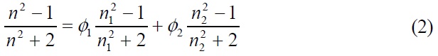
The similar simulated and experimental results have been shown in Fig. 7(b) and (c) with the volume ratios of toluene and chloroform as 8:2 and 9:1. The insertion losses are 3.5 dB and 4.1 dB at higher temperature range while the extinction ratios are about 18.1 dB and 23.9 dB, respectively. The temperature sensitive ranges are around 40℃ and 50℃ within the temperature interval of 5℃ while the intrinsic loss and splicing loss is about 3~4 dB. According to the numerical simulation, the high temperature-sensitive range corresponds to the refractive index of the cladding mixture liquids in the numerical interval from 1.454 to 1.457, which could be achieved through both different proportions of solutions from Equation (2) and functional relationship between temperature and the refractive index of the liquids from Equation (1). That is the physical mechanism for the tunable temperature sensitive range.
The simulation results and the experimental measurements in Fig. 7 present a good qualitative agreement in general with the slight discrepancies arising from the instabilities of liquid fluctuation, the uneven heating of temperature controller and the influence of external environment. Such a temperature tunable device could be developed as a thermo-optic sensor, attenuator or slow response optical switch with a tunable temperature sensitive range. The improvement of the quality of fusion splicing between SMF and MOF will lead to better model confinement and lower insertion loss. Additionally, the effective approaches to increase the extinction ratio lie in the increment of the thermo-optical coefficients and the enhancement of the interaction between the mode field and the infused materials.
In conclusion, we have demonstrated the thermo-optic characteristics of liquid-filling micro-structured optical fiber both theoretically and experimentally. Numerical simulation for the optimization of its structure has been operated and discussed in the aspects of the air-filling ratios