

Optimal preparation guidelines of a cathode catalyst layer by non-precious metal catalysts were evaluated based on electrochemical performance in single-chamber microbial fuel cells (MFCs). Experiments for catalyst loading rate revealed that iron(II) phthalocyanine (FePc) can be a promising alternative, comparable to platinum (Pt) and cobalt tetramethoxyphenylporphyrin (CoTMPP), including effects of substrate concentration. Results showed that using an optimal FePc loading of 1 mg/cm2 was equivalent to a Pt loading of 0.35 mg/cm2 on the basis of maximum power density. Given higher loading rates or substrate concentrations, FePc proved to be a better alternative for Pt than CoTMPP. Under the optimal loading rate, it was further revealed that 40 wt% of FePc to carbon support allowed for the best power generation. These results suggest that proper control of the non-precious metal catalyst layer and substrate concentration are highly interrelated, and reveal how those combinations promote the economic power generation of single-chamber MFCs.
Microbial fuel cells (MFCs) have received much attention due to advantages such as renewable energy production, direct electricity generation, simultaneous organic removal, and low temperature operation, which offer promising benefits for the sustainable recycling of organic wastes and wastewaters from human origin [1,2].
Analogous technologies stemmed from elementary twochamber MFC have many possible uses in the field of environmental science and engineering, and have been intensively investigated for various applications [2-4]. Such technologies are gradually becoming competitive to other physico-chemical energy conversion technologies, as the overall material costs associated with them drop. In the case of typical two-chamber MFCs, the cathode electrode, which is generally loaded with platinum (Pt), and the proton exchange membrane (PEM) were pointed out as the primary sources of cost [5]. Although a single-chamber MFC could completely reduce expenses from the PEM [6], the excellent performance of Pt was determined to be completely irreplaceable [7]. Despite the preference, however, exponentially rising costs for scaling-up made researchers investigate appropriate alternatives to Pt, such as iron(II) phthalocyanine (FePc) [8], cobalt tetramethoxyphenylporphyrin (CoTMPP) [9], activated carbon [10], stainless steel [11], nickel [12], and even microorganisms, as a biocatalyst material [13], which might reduce expense while maintaining performance.
The N4-chelate of transition metals on carbon support were regarded as one of the potential candidates that could replace Pt [8]. In particular, it was confirmed that the activity and longterm stability of the catalysts could be improved significantly by heat treatment at high temperatures [14]. Given this characteristics, the pyrolyzed metals porphyrin and phthalocyanine were studied as non-Pt-based cathode catalysts for a number of years. FePc- and CoTMPP-based cathode catalysts were tested as promising candidates, especially due to their promising oxygen reduction reaction [15].
One of biggest issues when applying non-precious metal catalysts is to incorporate materials appropriately, and to find optimal guidelines for cathode preparation. However, incoherent blending techniques were used for constituents of the catalytic layer were used: for example, Zhao et al. [15] used 2 mg/cm2 of FePc and CoTMPP, Harnisch et al. [16] employed 3 mg of FePc/Vulcan XC-72 mixture on a 1 cm2 graphite foil, whereas Cheng et al. [9] used 0.6 mg/cm2 of CoTMPP. Nonetheless, the catalyst loading rate has a direct impact on both electrochemical performance and material cost, yet little attention has been paid to the optimal blending of catalytic constituents.
The present paper investigates criteria for selecting a proper catalyst loading on a cathode surface for FePc and CoTMPP. Experimental results show how the catalyst loading rates and substrate concentration simultaneously affect the power performance in single chamber MFCs. On the basis of obtained criteria it then describes the proper weight percentage (wt%) between the non-precious metal catalysts and carbon supports. This combination of two mechanistically distinct preparations may form an optimal guideline in blending catalytic materials for cathodes of single-chamber MFCs.
2.1. Preparation Procedure of Carbon Supported Metal Catalysts
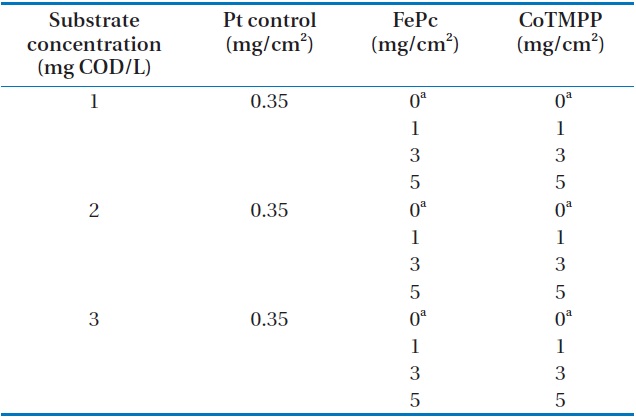
Commercially available catalysts, CoTMPP (Aldrich, St. Louis, MO, USA) and FePc (Aldrich) were used in this experiment to create carbon supported CoTMPP and FePc and a Pt catalyst (10 wt% Pt on Vulcan carbon; E-TEK, Natick, MA, USA) was purchased for the control experiment. All the procedures for catalysts preparation are described elsewhere [9,15]. For the production of carbon supported FePc catalyst, FePc was dissolved in concentrated H2SO4 (98%), and carbon powder (Vulcan XC-72; Cabot Corp., Billerica, MA, USA) was added to the mixture while stirring to meet the loading conditions of experimental design (Table 1). The resulting mixture was then poured into cold water and stirred overnight. The carbon-supported metal was filtered
[Table 1.] Experimental design for optimal dose of cathode catalyst using non-precious metals

Experimental design for optimal dose of cathode catalyst using non-precious metals
and washed with deionized water. Finally, the carbon-supported metal was heated under argon gas at 800℃ for 2 hr, before it was ball-milled. To produce carbon supported CoTMPP catalyst, we dissolved CoTMPP and carbon powder in acetone according to experimental design (Table 1). The mixture was stirred for 20 hr to keep its homogeneity, and then filtered to remove impurities. The purified mixture was heated to 800℃ supplying argon gas flow for 2 hr and then ball-milled before use. As a control catalyst, commercial 10 wt% Pt on Vulcan XC-72 was used directly.
2.2. Cathode Electrode Preparation
To investigate the electrochemistry of the prepared catalysts on the surface of the cathode, 30 wt% wet-proofed carbon cloth (type B, E-TEK; projected surface area = 12 cm2) was used as a backbone cathode electrode. To supply sufficient oxygen, a diffusion layer was prepared following procedures described elsewhere [6,17]. On the other surface of carbon cloth, we applied different loading of metal catalysts, as listed in Table 1. The carbon-supported catalysts of FePc and CoTMPP were mixed with 5% Nafion solution (Aldrich) according to the experimental design, and then painted on the carbon cloth to be 1 mg/cm2 (FePc1 and CoTMPP1), 3 mg/cm2 (FePc3 and CoTMPP3), and 5 mg/cm2 (FePc5 and CoTMPP5). To compare the electrochemical performance between the non-precious metal and precious Pt, a Pt control experiment (PtMFC) was conducted simultaneously, using the Pt loading rate of 0.35 mg/cm2. A bare cathode without any catalyst was also tested for each substrate concentration as a control experiment (CMFC).
At the best catalyst loading, we blended CoTMPP or FePc with carbon black powder to differentiate weight percentage of metal catalysts to be 20, 40, and 60 wt%, which will eventually show different thickness of catalyst layer on the cathode. Small weight percentage means higher amount of carbon black power, equivalent to a thicker catalyst layer on the surface.
2.3. MFC Set-up and Operation Procedures
Single-chamber MFCs were designed using 250 mL square bottles (Nalgene 2016; Thermo Scientific, Waltham, MA, USA). An anode of graphite felt (4 cm × 5 cm; National Electric Carbon Products, Greenville, SC, USA) was installed in the middle of the bottles by a titanium wire. Each cathode as well as anode was connected with the titanium wire, equipped with pluggable bulkhead connectors, and wired to an external resistance (1,000 Ω) constituting a closed electrical circuit. All MFCs were inoculated using activated sludge from a wastewater treatment plant that had a volatile suspended solid concentration of 3.5 g/L.
After inoculation, the external resistance was shifted from 1,000 Ω to 100 Ω. The initial media solutions contained 16.2 mM of acetate (? 1 g COD/L), 50 mM of phosphate buffer, 5.8 mM of NH4Cl, 1.7 mM of KCl, a trace metal salt, and vitamin solution [17]. Initial pH was adjusted to 7 using 1 M HCl and H2SO4 solutions. All the MFCs were operated in duplicate at a constant temperature (35℃) and the average values were reported.
The performance of each MFC was monitored by analyzing electrical data using a multimeter (model 2700; Keithley Instruments, Cleveland, OH, USA) and samples (2 mL) taken from a sampling port. Current (
is the resistance (Ω) and
3.1. Effects of Catalyst Loadings and Substrate Concentrations
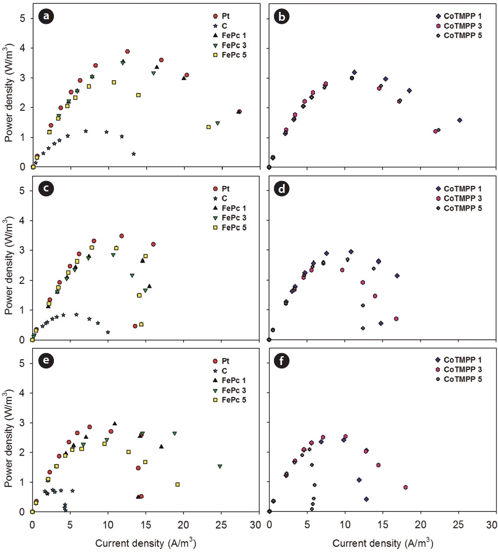
Fig. 1 presents the dynamics of maximum power densities obtained from the polarization analyses for various non-precious metal loadings (0?5 mg/cm2) at different substrate concentrations: 1,000, 2,000, and 3,000 mg COD/L (Fig. 2). These results compare how FePc and CoTMPP catalyze the power generation in single chamber MFCs. It is clear that FePc-MFCs generated 2.3?4.1 fold higher power densities (2.3?3.5 W/m3) than did CMFCs (0.7?1.2 W/m3) at each operating condition, while CoTMPP-MFCs showed slightly lower power densities (2.1?3.2 W/m3) than those of FePc-MFCs. The corresponding power output based on the cathode surface area were 11?17 W/m2 for FePc-MFCs, 10?15 W/m2 for CoTMPP-MFCs, and 3.4?5.8 W/m2 for CMFCs. Even though non-precious metal catalyst increased the maximum power densities, too much loading did not always lead to enhanced performance. For both FePc and CoTMPP-MFCs, a loading of 1 mg/cm2 showed the best performance in terms of power generation, and regardless of the substrate concentration, while higher loadings (>3 mg/cm2) had slightly decreased power generation for both catalysts (approximately 23% for FePc and 13% for CoTMPP).
From the absolute value of maximum power density, 1 mg/cm2 was revealed as the optimal operating conditions for both FePc (3.0?3.5 and 14?17 W/m2) and CoTMPP (2.4?3.2 and 12?15 W/m2). As the catalyst loading for the cathode increased up to 5 mg/cm2, the power density diminished about 19% for FePc and 6% for CoTMPP. The maximum power densities of FePc1-MFC and FePc3-MFC were almost equal (3.5 W/m3); however, FePc1- MFC was superior to FePc3-MFC in the higher current region than 12 A/m3 (Fig. 2) and this was also the case between Co- TMPP3-MFC and CoTMPP5-MFC. In addition, as the substrate concentration increased, the power densities based on reactor volume reduced by about 16% for FePc and 24% for CoTMPP, respectively. These results imply that catalysis by either FePc or CoTMPP is sensitive to both catalyst loading and substrate limitation. In contrast with the traditional one-way optimization of catalyst loading, these findings provide evidence for the simultaneous consideration of catalyst and substrate characteristics that can significantly influence electrochemical performance. Statistical analysis using Pearson correlation support that the electrochemical performance of CoTMPP is more positively correlated to catalyst loading rates (correlation coefficient = 0.55, p = 0.06) than that of FePc, meaning stable power generation of FePc rather than CoTMPP. For substrate concentration, both catalysts showed a negative correlation (-0.27 for FePc and -0.33 for CoTMPP), indicating that potential inhibition tends to decrease power generation as the substrate concentration increases.
3.2. Feasibility of Non-precious Metal Catalysts
To examine the feasibility of optimized FePc and CoTMPP loading, the power performances of FePc and CoTMPP were compared with that of PtMFC. PtMFC showed the highest performance (3.9 and 19 W/m2) at 1,000 mg COD/L (Fig. 2). Despite the highest performance in power density, the performance of FePc was only 9% (10%, cathode area basis) less than that of Pt, while CoTMPP was 18% (22%, cathode area basis) lower. It is known that the loading of Pt showed a positive linear relationship with power as a cathode catalyst [9], which contrasted with the results of this study. In cases of FePc and CoTMPP, it was found that the optimum point of catalyst loading exists for MFCs, as shown earlier in chemical fuel cells [18]. The differences in open circuit voltage (OCV) between PtMFC (0.71?0.74 V) and other MFCs (0.66?0.72 V) were not significant, and also support that OCV of FePc and CoTMPP are within the range of
relevant variability, for which standard deviations were ±0.35 and ±0.26 V, respectively [19].
At substrate concentrations higher than 2,000 mg COD/L, the power generation of FePc1-MFC (3.0 W/m3) was highly preferable as it was compared to that of PtMFC. FePc3- and FePc5-MFCs maintained higher voltages at a higher current density, which means that higher FePc loading (>3 mg/cm2) could be more advantageous than Pt for the treatment of highly concentrated wastewater (>3,000 mg COD/L).
It was identified that the FePc and CoTMPP loading rate (1 mg/cm2) was comparable to 0.35 mg/cm2 Pt, and higher loading rates were found to be suitable for the representation of concentrated wastewater treatment. These results provide a quantitative framework to help predict the effects of alternative catalyst loading and substrate concentration, or both, on the power generation of MFCs.
3.3. Relationships of Coulombic Efficiencies to Catalyst Loadings and Substrate Concentrations
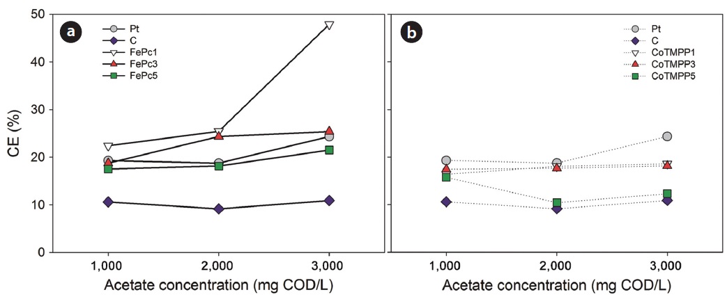
Fig. 3 compares coulombic efficiency (CE) along with the variation of substrate concentration. In most cases, main substrate HAc was almost completely removed (>99%) for all the operating conditions; however, CE showed a clear difference between FePc and CoTMPP. The CE of FePc-MFC increased with the substrate concentration, in a similar with the trend of the CE of PtMFCs. Also, the CE of FePc1-MFC, showing the highest performance among all the MFCs tested, increased from 24% at 1,000 mg COD/L to 48% at 3,000 mg COD/L, while the CE of PtMFC only increased up to 27% at the same range of substrate concentration. The CEs of FePc3-MFC and FePc5-MFC increased similarly from 20% to 25%, respectively. For CoTMPP, however, the substrate concentration had no significant effect on the CEs. Although obtained CEs stabilized despite the loading rates of CoTMPP, all the CEs of CoTMPP-MFCs showed lower values than PtMFCs, and inferior results to those of FePc-MFCs as well.
3.4. Variation of Metal Loading on Carbon Supports
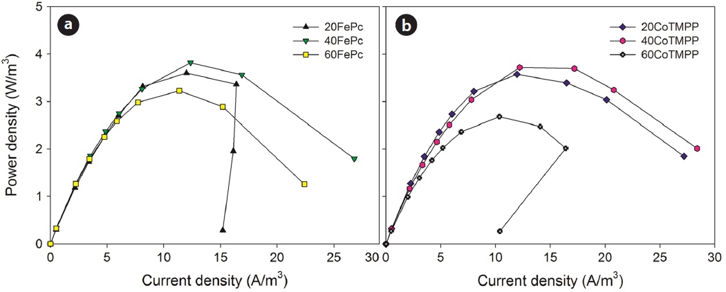
Keeping the catalyst loading rate for the cathode constant, the amount of carbon support (Vulcan XC-72 in this study) can alter the overall thickness of the catalyst layer. This characteristic can be represented as the weight percentage of catalysts over the total catalyst blend, deposited on the cathode surface. Thus it was evaluated how the weight percentage of the non-precious metal over the total catalyst blend affects the overall power generation of MFCs. In this study, 20, 40, and 60 wt% of FePc (20FePC, 40FePc, and 60FePc) and CoTMPP (20CoTMPP, 40CoTMPP, and 60CoTMPP) were tested at the optimal catalyst loading (1 mg/cm2), respectively. Lower weight percentages of catalysts indicate a thicker catalytic layer depth than the cases of higher percentages, due to the larger amount of carbon support.
Fig. 4 demonstrates the performance difference in the power density curves. For FePc, the thicker catalyst layer (20 wt%) showed a significant decline in power generation, especially in the higher range of current density than 15 A/m3. This may indicate that the thick catalyst layer can interrupt the electron transfer and electrochemical reaction in the cathode, possibly due to the water generated from the catalyst layer. For both catalysts, it was commonly shown that 40 wt% of metal catalyst was the most favorable content (Fig. 3), and the maximum power densities were 3.7 W/m3 (18 W/m2) for 40FePc-MFC and 3.6 W/m3 (17 W/m2) for 40CoTMPP-MFC, respectively. These results also support that 40 wt% is highly appreciable for the non-precious metal catalysts, when compared with 10 wt% of Pt. For 60FePc and 60CoTMPP, however, the obtained maximum power densities were significantly reduced to 3.2 and 2.7 W/m3 (15 and 13 W/m2), respectively. This phenomenon was more severe for CoTMPP, suggesting that the higher percentage of metal catalysts (>40 wt%) is not advantageous in power generation, because a significant decrease in total conductive area of the carbon support may reduce electrochemical performance, as previously indicated by Siswana et al. [20].
All of this data evidence indicates that charge transfer is drastically limited by the thickness or surface area of the catalytic layer. Thus, it was confirmed that the quantitative difference of carbon support limits power generation, and that an optimal blend of non-precious metal catalyst and carbon support which achieves the best power generation should be used in a singlechamber MFC.
These findings contribute to the understanding that matching catalyst loading rate of cathode and substrate concentration in single-chamber MFCs is highly interrelated for economic power generation, especially when non-precious metal catalysts are used. FePc has significantly better potential than CoTMPP as an alternative material, as it is comparable. Given 1 mg FePc/cm2 and 1,000 mg COD/L, power generation, the CE and economical feasibility of FePc-MFC were similar to those of the PtMFC. For higher loading and substrate concentration, FePc-MFC shows better performance. Also, weight percentages of non-precious metals on carbon supports show a distinct impact on the performance of single-chamber MFCs, as an important design parameter.


