For underpasses in Yeongjong Sky City business district, the guided drainage system, as a buoyancy prevention system has been designed, and is under construction. This paper investigates the safety of the guided drainage system for underpass structures being constructed in Yeongjong Sky City business district. This paper also calculates the amount of outflowing groundwater generated by the guided drainage system, and proposes alternative usages of the water. In order to investigate safety and field applicability of the guided drainage system for underpasses, characteristics of the surface flow for the area of interest have been analyzed, and the flow change of groundwater following the underpass structure construction has been evaluated using the 3-dimensional groundwater program MODFLOW. The influence of ground water on safety of the underpass structures has been calculated by FLAC2D analysis. For alternative usages for the outflowing groundwater generated by the guided drainage system, utilization methods of the outflowing groundwater in national and international resources have been researched. The amount of an outflowing groundwater to be generated in the area of interest has been analyzed, and efficient potential usages of this groundwater have been researched. When guided drainage technique is applied, the change in flow of groundwater must be evaluated and considered as safety factor relating to the buoyancy of the structure. As a result, safety factor demonstrated more than 1.2, meaning that the underpass structure is safe. The amount of subsoil drain generated by the guided drainage system was also analyzed. The quality and amount of water satisfied the standards and volume requirements, so as to make it applicable for a number of uses, such as X, Y, and Z, and should prove to be a valuable resource as the circumstances of the neighboring area change over time. These resources can be used as basic data for future urban water circulation studies, as well as generating research of alternative water usages.
Currently in Yeongjong Sky City business district, a guided drainage system, as a buoyancy prevention measure, is under construction [1]. The guided drainage system is considered to be exceptionally economical due to its safety-focused design as an earth-anchor (preventing buoyancy through the diversion of groundwater). However, such a system has never before been applied in the field, and thus, there is an urgent need for verification of the long-term safety, the change of groundwater surface level for the area of interest, and economic feasibility.
In order to investigate the safety and field applicability of the guided drainage system for underpasses, characteristics of the surface flow for the area of interest have been analyzed, and the flow change of groundwater following the underpass structure construction has been evaluated using a 3-dimensional groundwater flow program, MODFLOW. The influence of ground water on safety of the underpass structures has been calculated by FLAC2D analysis (Itasca, Minneapolis, MN, USA). For alternative usages for the outflowing groundwater generated by the guided drainage system, utilization methods of the outflowing groundwater in national and international resources have been researched. The amount of outflowing groundwater expected to be generated in the area of interest has been analyzed so as to evaluate the efficiency.
2.1. Status of the Area of Interest
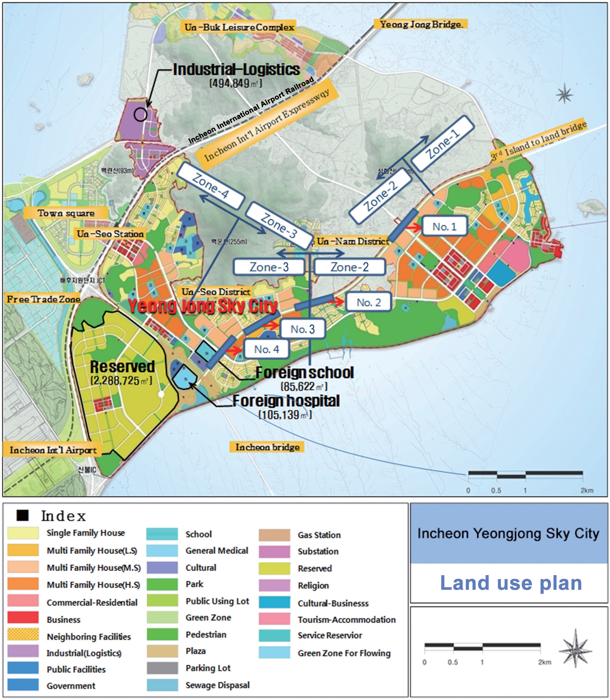
The areas of study in this paper were underpasses no. 1?4 within structure zones 2 and 3 in the Yeongjong Sky City business district, Jung-gu, Incheon, South Korea and the neighboring
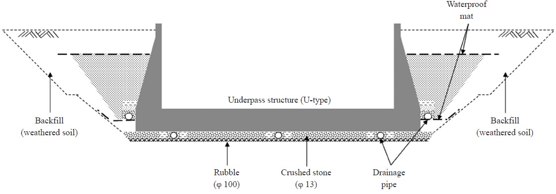
areas (Fig. 1). The guided drainage system applied in the underpass for the area of interest is shown in Fig. 2.
2.2. Analysis of Characteristics of Groundwater Flow
Hydrological characteristics of the area of interest were analyzed by Storm Water Management Model (SWMM) program and the analyzed data were used as basic data to analyze the characteristics of the groundwater flow [2,3]. Flow change in groundwater following the underpass structure construction was analyzed by the 3-dimensional groundwater MODFLOW program [4]. Results indicated that the average level of groundwater in the area before the construction of the underpass was 1?2 m above ground level, which as a critical distinction in terms of the engineering of this area. After construction of the underpass with guided drainage system, the groundwater level in the area decreased 3?4 m before the underpass construction. Groundwater level at the U-type finishing point and at the starting point was formed at least more than 6.2 m and 3.4 m below ground level, respectively.
3.1. Evaluation on Safety and Displacement of Underpass Structure
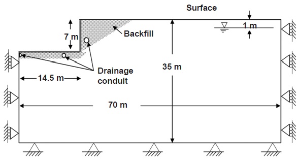
The influence of ground water on safety of the underpass structures has been calculated by FLAC2D analysis. The results were interpreted from various conditions by cases. Three main conditions for the evaluation are as follows: application of guided drainage system, longitudinal level of underpass and ground (Fig. 3).
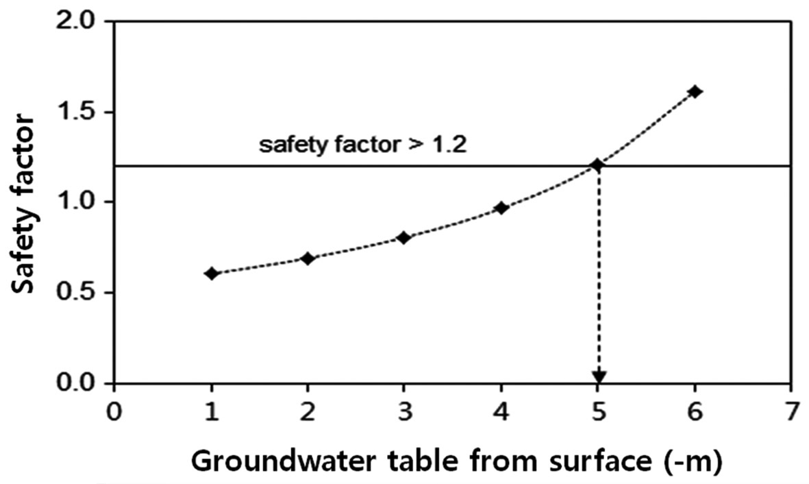
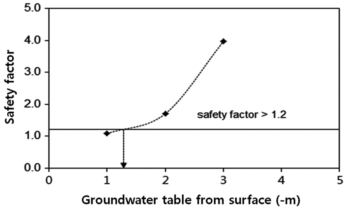
For cases in which the buoyancy prevention (guided drainage system) was not applied, the minimum groundwater level was analyzed to secure a safety factor based on the dead load. Analysis of the result indicated a safety factor of over 1.2 when the groundwater level of the underpass dropped by more than 5.0 m below ground level at the U-type finishing point, and at least 1.2 m below ground level at the starting point (Figs. 4 and 5).
3.2. Amount of Subsoil Drain by Guided Drainage System
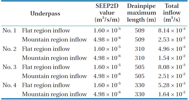
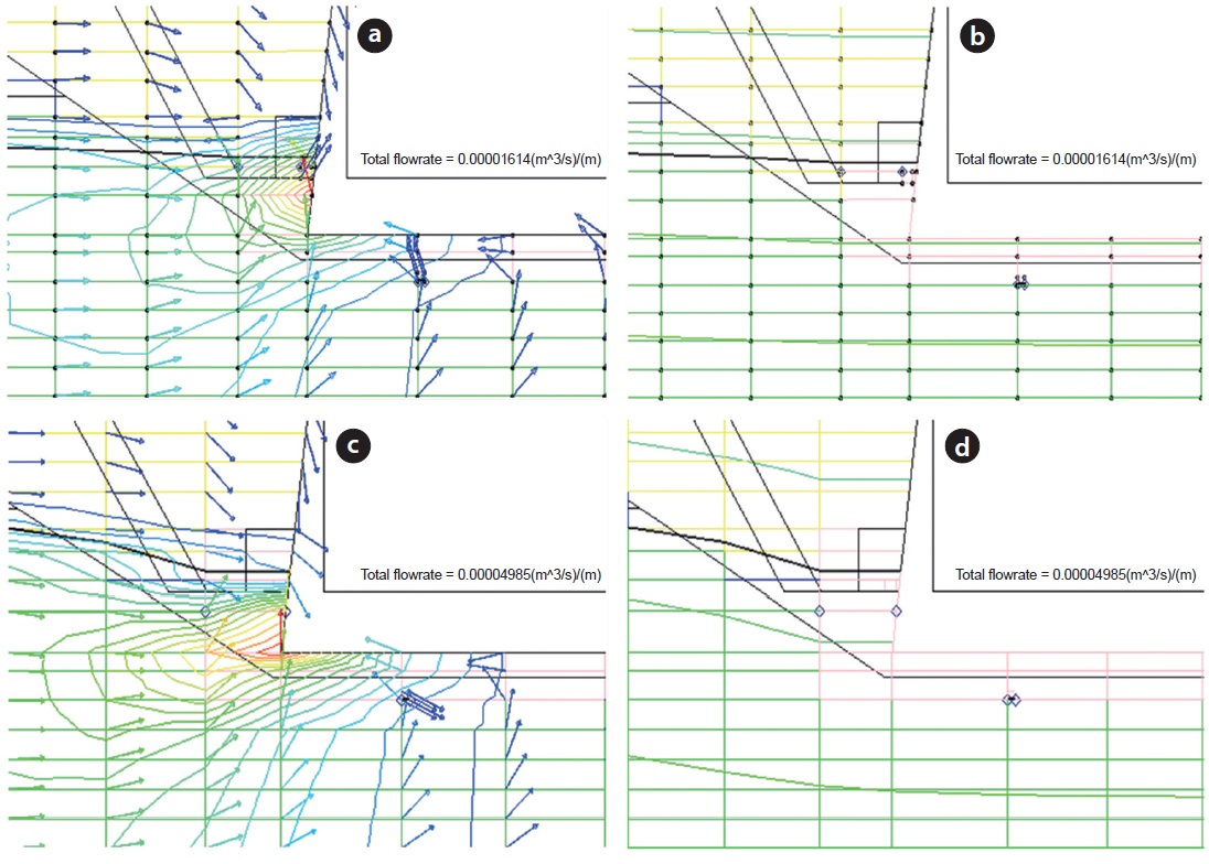
The amount of subsoil drain by the guided drainage layer was calculated by SEEP2D program. Analysis section of the program was selected at two regions: mountain region and flat region, and the results showed that inflow to the drainpipe by guided drainage system was 8.14 × 10⁻³ m3/s for the flat region, and 2.53 × 10⁻² m3/s for the mountain region (Table 1 and Fig. 6).
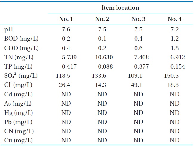
In order to investigate alternative water usages, the groundwater quality was determined at the points where the guided drainage system is applied. As can be seen from Table 2, the groundwater in the area was determined as: pH, 7.2?7.6; biochemical oxygen demand, 1.2 mg/L; total nitrogen (TN), below 10.63 mg/L; and total phosphorus (TP), below 0.42 mg/L. Except for TN and TP, and the results indicate that the groundwater in the area was in agreement with the lb rating for treated water quality and stream water quality.
Songsan and Yeongjong Water Quality Restoration Centers,
[Table 1.] The SEEP2D analysis result

The SEEP2D analysis result
where are currently under construction in Yeongjong Sky City, are planning to apply advanced wastewater treatment systems, and to reuse the treated wastewater for stream maintenance in the Sky City. The volume of water to be reused for maintenance is planned at 18,000 m3/day per center, and a budget for stream maintenances is allocated at about 530 million Korean won per year in the Songsan Water Quality Restoration Center. Underpass no. 1 is located in Songsan treatment zone and no. 2?4 are located
[Table 2.] Groundwater quality analysis results

Groundwater quality analysis results
in Yeongjong treatment zone. All underpasses are within 1 km of the water sources which are scheduled to receive inputs from the Water Quality Restoration Center.
Using the SEEP2D model, the amounts of subsoil drainage per underpass were calculated as 428?2,160 m3/day, and when considering the resurgence of water into the area it is expected to less than 400?600 m3/day. Ground water flow of three locations on underpasses no. 2?4 were about 1,200?1,800 m3/day, which correspond to 10% of the water demand for stream maintenance in Yeongjong Water Quality Restoration Center. If 10% of the water supply were replaced by the subsoil drain generated by the guided drainage system, then there should be a comparable reduction in the volume of water which needs to be applied to advanced treatment (largely chemical costs).
However, for sustainable maintenance of the water supply for streams, long-term observations (e.g., 1?2 years) of subsoil drainage after the construction of underpass must be carried out, and a summation of initial installation costs (e.g., pump, duct line installation, etc.) should be carried out.
The purpose of this paper is to investigate the safety of a guided drainage system for underpass structures being constructed in Yeongjong Sky City business district in Incheon Free Economic Zone and to propose alternative usages for outflowing groundwater generated by the guided drainage system.
1) The characteristics of flow changes in groundwater following construction of the underpass structure showed that with the guided drainage system applied, the water level for groundwater at the U-type finishing point was at least 6.2 m below ground level, and at the starting point at least 3.4 m below ground level. The safety factor for the buoyancy of the structure was demonstrated to be more than 1.2 when the groundwater level was lowered by more than 5.0 m below ground level at the U-type finishing point, and at least 1.2 m below ground level at the starting point, meaning that the safety for the underpass structure is secure.
2) As of October 2011, water qualities for sewage water, treated wastewater and recycled water were found to meet the standards for use, and the amount of groundwater flow generated by the guided drainage system was calculated to be 428?2,160 m3/day per underpass. The quality and amount of water met the relevant standards and quantities to be used in a various of ways in the future [5].
3) If about 10% of the water supply for stream maintenance arising from the Songsan Water Quality Restoration Center [6], which is under construction in the area of interest, were replaced by the groundwater flow generated by the guided drainage system, up to 10% of the water treating cost might be mitigated. Considering that the neighboring area is still under development, careful reviews for alternative usages of this water should be based on the future changes in the area, rather than immediate concerns.