검색 전체 메뉴
PDF
맨 위로
OA 학술지
Metamaterial-Based Zeroth-Order Resonant Antennas for MIMO Applications
  • 비영리 CC BY-NC
  • 비영리 CC BY-NC
ABSTRACT
Metamaterial-Based Zeroth-Order Resonant Antennas for MIMO Applications
KEYWORD
Epsilon Negative , Metamaterial , MIMO , Mu Negative , Zeroth-Order Resonant.
  • Ⅰ. Introduction

    Multiple-input multiple-output (MIMO) technology is now widely employed in order to increase the reliability and the channel capacity of modern wireless communication systems. However, the available space for antennas in recent mobile terminals is very limited. Moreover, meeting the requirements of compact size, high isolation, low envelope correlation, and high radiation efficiencies in limited space usually available is quite challenging [1,2]. To achieve these goals, many antenna structures have been proposed. In [3], a planar inverted- F antenna (PIFA) with a dual-feed was presented. Two PIFAs are placed at the corners of a mobile terminal for the largest possible separation, utilizing polarization diversity [4]. There have been trials to use photonic band-gap or split ring resonator [5] structures between the radiation elements in order to improve the isolation. A decoupling network [6] is one promising means of satisfying the MIMO requirements. However, these two methods require an additional structure or circuit between the antennas. To overcome this problem, we adopt two types of metamaterial (MTM) zeroth-order resonant (ZOR) antennas. One is the epsilon-negative (ENG; open terminated) antenna, and the other is the mu-negative (MNG; short terminated) antenna [7]. It is well known that MTM ZOR antennas can be made as small as possible. In addition, it will be shown that the performance of the proposed MIMO system far surpass those of recent works in terms of the size, isolation, envelope correlation, and antenna efficiencies.

    Ⅱ. Antenna Design and Simulation

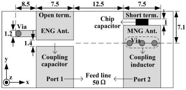
    Fig. 1 shows the geometry of the proposed MIMO system composed of the ZOR ENG and MNG antennas with their dimensions designed at 2.2 GHz. The antennas are fed by two 50 Ω microstrip lines with width of 7.5 mm on a Teflon substrate (εr, 2.2; height, 2.37 mm). Since the ENG antenna has an open termination and its propagation constant β is zero (zeroth-order), the series current is negligible and the shunt voltage wave (or electrical field) is dominant in the entire structure with the same phase. For the MNG antenna with a short termination, the opposite is true with a dominant series current. The electric fields generated by this current are orthogonal to those in the ENG antenna. For this reason, the coupling between the two antenna elements becomes very small.

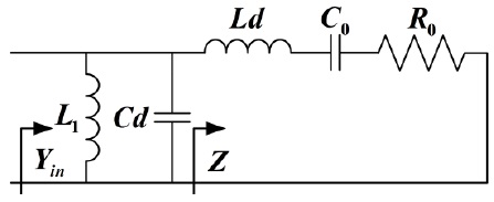
    In Fig. 2, we show the equivalent circuit of the MNG antenna short-terminated. The electrical length
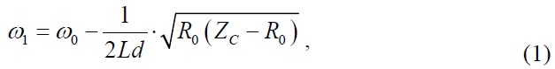
 kd of the host transmission line is π/6 radians at 2.4 GHz and the characteristic impedance Zc is 50 Ω. This is equivalent to the fact that the series inductance Ld is 1.74 nH and the shunt capacitance Cd is 0.69 pF. Since the propagation constant β is required to be 0 at the transient frequency of f0=2.4 GHz, C0 is determined to be 2.5 pF [7]. Furthermore, R0 is extracted to be 0.23 Ω. Since R0 is very small and direct matching to the feed line is not possible, a coupling inductor with L1 is usually required. By equating the input admittance Yin to the characteristic admittance Yc of the feed line, we can find a new resonant angular frequency ω1 given by

    image

    and L1 is found to be

    image

    In (1), as R0Zc or 0, ω1ω0, and ω1 becomes the lowest when R0 is Zc/2. Using (1) and (2), the new resonant frequency f1 becomes 2.23 GHz and L1 is calculated to be 0.23 nH, realized using three vias with radius 0.5 mm as seen in Fig. 1.

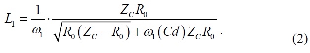
    For the ENG, the equivalent circuit is exactly the dual of Fig. 2 [8]. The calculated shunt inductance L0 is 6.2 nH, realized with a shorted stub, and G0 is extracted to be 0.0001 S. The coupling capacitance C1 for matching to the feed line is 0.1 pF, realized with a gap, as seen in Fig. 1. The overall MIMO antenna system is very compact (0.26×0.05 λ0).

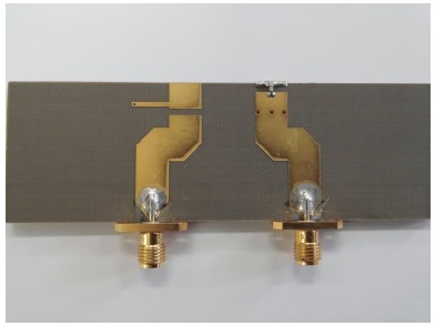
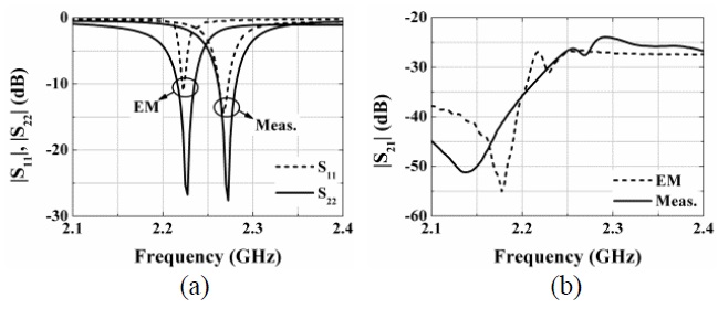
    Fig. 3 shows the photograph of the MIMO system consisting of ENG and MNG antennas. Two feed lines have been somewhat bent away from each other for easy mounting of SMA connectors. Fig. 4(a) and (b) show the electromagnetic (EM)-simulated and measured |S11| (ENG), |S22| (MNG), and |S21|. Their resonant frequencies are shown to be off by about 0.04 GHz, possibly due to fabrication inaccuracy. The EM-simulated and measured resonant frequencies are 2.23 and 2.27 GHz, respectively. Although the spacing between the ENG and MNG is only 0.09 λ0, the isolation (|S21|) which has been measured using a network analyzer is relatively high (27.6 dB) at 2.27 GHz.

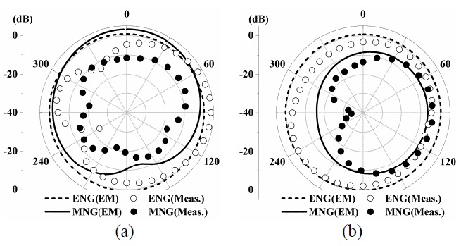
    In Fig. 5(a) and (b), we show the gain patterns Eθ and E of the ENG and MNG antennas, respectively, in the yz plane. The EM-simulated and measured patterns of E are in a better agreement than those of Eθ. The difference between the EM-simulated and measured pattern of Eθ is believed to come from the fabrication error. Due to the small size of the antennas and ground plane, they show near-isotropic patterns. The envelope correlation [9] of the proposed antenna has been computed to be very small (0.015). This result is due to the near-orthogonally radiated fields, evaluated over all 4π solid angles.

    [Table 1.] Comparison of multiple-input multiple-output antenna performances

    label

    Comparison of multiple-input multiple-output antenna performances

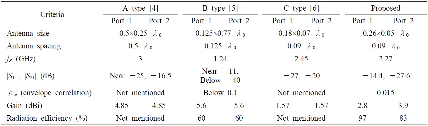
    In Table 1, the various performances of the proposed antennas are compared with those in [4] (A type), [5] (B type), and [6] (C type), and the proposed antennas prove to be superior to the others to the best of our knowledge. The gains and radiation efficiencies of the each antenna were measured while the one port was connected to the source and the other one was matched.

    Ⅲ. Conclusion

    A very compact MTM-based ZOR MIMO system consisting of ENG and MNG structures has been designed, fabricated, and evaluated in terms of its size, isolation, envelope correlation, and radiation efficiencies. The performances of the proposed antenna have been compared with those of recent competitive works. Despite the small separation (0.09 λ0) between the proposed radiation elements, the isolation is relatively high (27.6 dB) at 2.27 GHz. The envelope correlation has been found to be negligibly small (0.015). The efficiencies are about 90% on average. The proposed ZOR MIMO antenna system is considered to be an immediate candidate for the very compact mobile handsets of today.

참고문헌
  • 1. Svantesson T. 2002 "Correlation and channel capacity of MIMO systems employing multimode antennas" [IEEE Transactions on Vehicular Technology] Vol.51 P.1304-1312 google cross ref
  • 2. Kildal P. S., Rosengren K. 2004 "Correlation and capacity of MIMO systems and mutual coupling, radiation efficiency, and diversity gain of their antennas: simulations and measurements in a reverberation chamber" [IEEE Communications Magazine] Vol.42 P.104-112 google cross ref
  • 3. Chattha H. T., Huang Y., Boyes S. J., Zhu X. 2012 "Polarization and pattern diversity-based dual-feed planar inverted-F antenna" [IEEE Transactions on Antennas Propagation] Vol.60 P.1532-1539 google cross ref
  • 4. Al-Nuaimi M. K. T., Whittow W. G. 2011 "Performance investigation of a dual element IFA array at 3 GHz for MIMO terminals" [in Proceedings of the Loughborough Antennas & Propagation Conference] P.1-5 google
  • 5. Bait-Suwailam M. M., Boybay M. S., Ramahi O, M. 2010 "Electromagnetic coupling reduction in highprofile monopole antennas using single-negative magnetic metamaterials for MIMO applications" [IEEE Transactions on Antennas Propagation] Vol.58 P.2894-2902 google cross ref
  • 6. Chen S. C., Wang Y. S., Chung S. J. 2008 "A decoupling technique for increasing the port isolation between two strongly coupled antennas" [IEEE Transactions on Antennas and Propagation] Vol.56 P.3650-3658 google cross ref
  • 7. Jang S., Lee B. 2011 "Modelling and design of resonant one-dimensional metamaterial-based transmission lines for antenna applications" [IET Microwaves Antennas & Propagation] Vol.5 P.1529-1536 google cross ref
  • 8. Kim T. G., Lee B. 2009 "Metamaterial-based compact zeroth-order resonant antenna" [Electronics Letters] Vol.45 P.12-13 google cross ref
  • 9. Blanch S., Romeu J., Cordella I. 2003 "Exact representation of antenna system diversity performance from input parameter description" [Electronics Letters] Vol.39 P.705-707 google cross ref
OAK XML 통계
이미지 / 테이블
  • [ Fig. 1. ]  Geometry of proposed multiple-input multiple-output system consisting of epsilon-negative (ENG) and mu-negative (MNG) antennas (unit: mm).
    Geometry of proposed multiple-input multiple-output system consisting of epsilon-negative (ENG) and mu-negative (MNG) antennas (unit: mm).
  • [ Fig. 2. ]  Equivalent circuit for the short-terminated mu-negative antenna.
    Equivalent circuit for the short-terminated mu-negative antenna.
  • [ Fig. 3. ]  Fabricated multiple-input multiple-output system.
    Fabricated multiple-input multiple-output system.
  • [ Fig. 4. ]  Electromagnetic (EM)-simulated and measured S-parameters of the proposed antenna: (a) |S11|, |S22| and (b) |S21|.
    Electromagnetic (EM)-simulated and measured S-parameters of the proposed antenna: (a) |S11|, |S22| and (b) |S21|.
  • [ Fig. 5. ]  Electromagnetic (EM)-simulated and measured gain patterns in yz plane: (a) Eθ and (b) E?. ENG=epsilon-negative, MNG=mu-negative.
    Electromagnetic (EM)-simulated and measured gain patterns in yz plane: (a) Eθ and (b) E?. ENG=epsilon-negative, MNG=mu-negative.
  • [ Table 1. ]  Comparison of multiple-input multiple-output antenna performances
    Comparison of multiple-input multiple-output antenna performances
(우)06579 서울시 서초구 반포대로 201(반포동)
Tel. 02-537-6389 | Fax. 02-590-0571 | 문의 : oak2014@korea.kr
Copyright(c) National Library of Korea. All rights reserved.