검색 전체 메뉴
PDF
맨 위로
OA 학술지
High-Efficiency, High-Gain, Broadband Quasi-Yagi Antenna and Its Array for 60-GHz Wireless Communications
  • 비영리 CC BY-NC
  • 비영리 CC BY-NC
ABSTRACT
High-Efficiency, High-Gain, Broadband Quasi-Yagi Antenna and Its Array for 60-GHz Wireless Communications
KEYWORD
Microstrip-Slotline Transition , Quasi-Yagi Antenna , Y-Junction Power Divider , 60 GHz Communications.
  • Ⅰ. Introduction

    Antennas for 60-GHz high-throughput and short-distance systems have been attracting considerable attention in the past few years because of the wide bandwidth and high atmospheric absorption offered by unlicensed wireless communications near the 60-GHz bands. In general, 60-GHz band antennas for wireless communication applications must be wideband, highly directive, low-profile, lightweight, low-cost, and easy to fabricate [1]. Accordingly, a quasi-Yagi antenna [2-7] is particularly suitable for 60-GHz applications because, unlike other designs [8-13], it satisfies all the above requirements.

    Various models of quasi-Yagi antennas have been introduced for 60-GHz wireless communications. For example, a CPW-fed Yagi antenna has been fabricated using a complementary metal-oxide-semiconductor compatible manufacturing technology [14]. A microstrip-fed Yagi-Uda antenna has been incorporated with metal-planes for shielding purposes [15]. A stacked Yagi antenna with a small footprint was presented in [16]. A substrate-integrated waveguide Yagi-Uda antenna having the advantages of low profile and light weight was reported in [17]. A four-element printed Yagi-Uda array using 18 directors was also proposed in [18]. However, most of these quasi-Yagi antennas lack the impedance bandwidth required to cover the entire 60-GHz bands (57 to 66 GHz).

    This paper describes a microstrip-to-slotline transitionfed quasi-Yagi antenna and its four-element array designed for 60-GHz wireless communication systems. A corrugated ground plane and five parasitic strips were employed as the reflector and directors of the antenna, respectively, to achieve a high level of directivity and small gain variation. The antennas yielded a broad impedance matching bandwidth as well as high radiation efficiency and high gain. We demonstrated the antenna characteristics, while simultaneously reducing the cost of the measurement process, by fabricating and measuring a scaled-up design of the proposed antenna operating at 15 GHz. The measurements resulted in an impedance bandwidth of 29.5% with a peak gain of 13.2 dBi and radiation efficiency better than 88%.

    Ⅱ. Design of Proposed Antenna

       1. Antenna Geometry

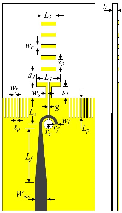
    Fig. 1 shows the geometry of a high-gain 60-GHz printed quasi-Yagi antenna. The antenna was designed on an 8 mm×22 mm Rogers RT/Duroid 5880 substrate with a dielectric constant of 2.2 and a loss tangent of 0.0009. The antenna was composed of a microstrip-to-slotline transition as the feed with an input impedance of 50 Ω, a truncated ground plane as a reflector, a printed dipole driver, and five parasitic strip directors. The 5 parasitic directors were chosen for the proposed antenna in order to achieve directivity greater than 10 dBi and the initial dimensions of the antenna were obtained from a table for maximum directivity in air [19] and then scaled to compensate for the RT/Duroid 5800 substrate and to achieve the maximum directivity. The ground plane was corrugated to improve the antenna gain with small gain variation. The antenna was fed by a novel microstrip-to-slotline transition, specially designed for 60-GHz bands.

    A full-wave electromagnetic simulator, the finite integration technique-based Microwave Studio by Computer Simulation Technology (MWS-CST), was used to investigate the characteristics of the proposed antenna. The design parameters of the optimized antenna were chosen in terms of wide impedance bandwidth, high directivity, and small gain variation, as follows: Wms=0.8 mm, Lf=5 mm, Ls=2 mm, rc=0.3 mm, rf=0.5 mm, wf=0.22 mm, g=0.1 mm, Lp=1.8 mm, sp=0.1 mm, wp=0.2 mm, ws=0.2 mm, S1=S2=S3=0.95 mm, L1= 1.8 mm, L2=1.3 mm, wc=0.4 mm, and h=0.254 mm.

       2. Microstrip-to-Slotline Transition

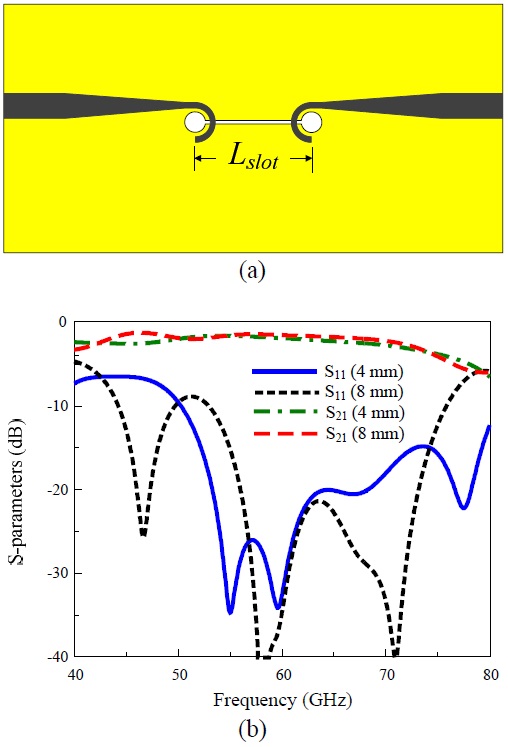
    As mentioned above, the 60-GHz printed quasi-Yagi antenna was fed by a novel microstrip-slotline transition that was specially designed for 60 GHz bands. Fig. 2(a) shows the back-to-back transition structure and Fig. 2(b) plots its simulated S-parameters for different slotline lengths (Lslot). The microstripline was designed on the back side of the substrate with characteristic impedance of 50 Ω and Wms=0.8 mm. The slotline was designed on the top side of the substrate with a characteristic impedance of 137 Ω and g=0.1 mm. The two impedances were matched by inserting a curved microstripline and circular slot into the transitions. The curved microstripline comprised a 50 to 100 Ω tapered feedline as a wideband transformer and half of a printed ring. The transformer was shaped from the wideline width (Zo=50 Ω) to the narrow-line width (Zo=100 Ω) with a length Lf=5 mm. The half of the printed ring had a line width wf=0.22 mm and a radius rf=0.5 mm. The circular slot was etched onto the ground plane with a radius rc=0.3 mm. As shown in Fig. 2(b), for both cases of Lslot=4 mm and Lslot=8 mm, the reflection (S11) and transmission (S21) coefficients were < ―20 dB and approximately ―2 dB, respectively, at 57 to 66 GHz. These made the transition widely suitable for 60 GHz communications.

       3. Corrugated Ground Plane

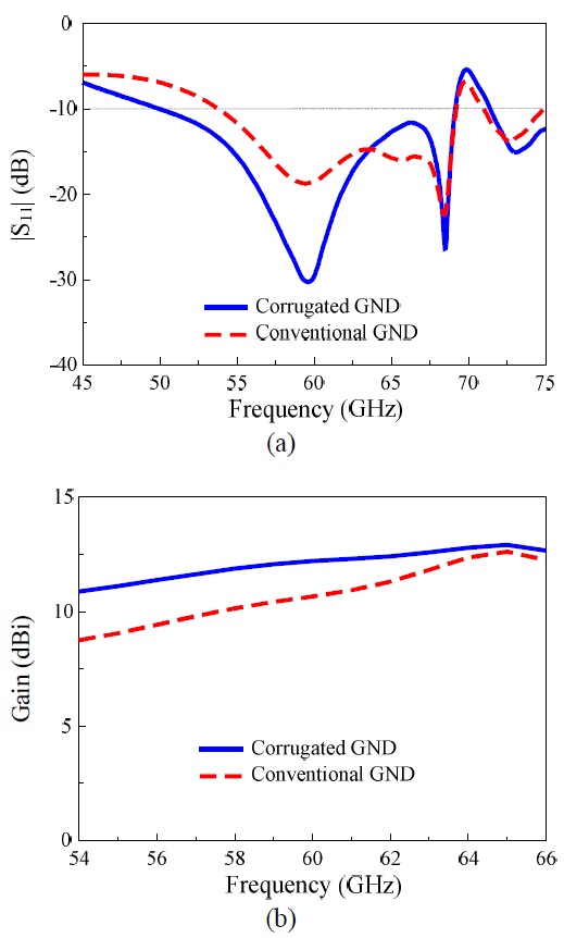
    The corrugated ground plane was employed as a magnetic ground plane edge to improve the front-to-back ratio at a given frequency [20]. On the other hand, the proposed antenna utilized a corrugated ground plane to enhance the bandwidth and improve the gain in the low-frequency region of the operating bandwidth. This can be observed in Fig. 3, which shows a comparison of antenna characteristics with conventional and corrugated ground planes. The bandwidth was extended in the low-frequency region, but it changed little in the high-frequency region with the corrugated ground plane, as shown in Fig. 3(a). The antenna had a maximum gain of 12.2 dBi at 64 GHz and a gain variation of 9.5 to 12.2 dBi with the conventional ground plane. The corrugated ground plane changed these values to a maximum gain of 12.77 dBi at 62.5 GHz and a gain variation of 10.50 to 12.77 dBi at 50 to 66 GHz, as shown in Fig. 3(b). These results indicate that antenna gain can be improved in the low frequency of the operating bandwidth by using the corrugated ground plane, and consequently, small gain variation can be attained.

    Ⅲ. Four-Element Array

       1. Mutual Coupling

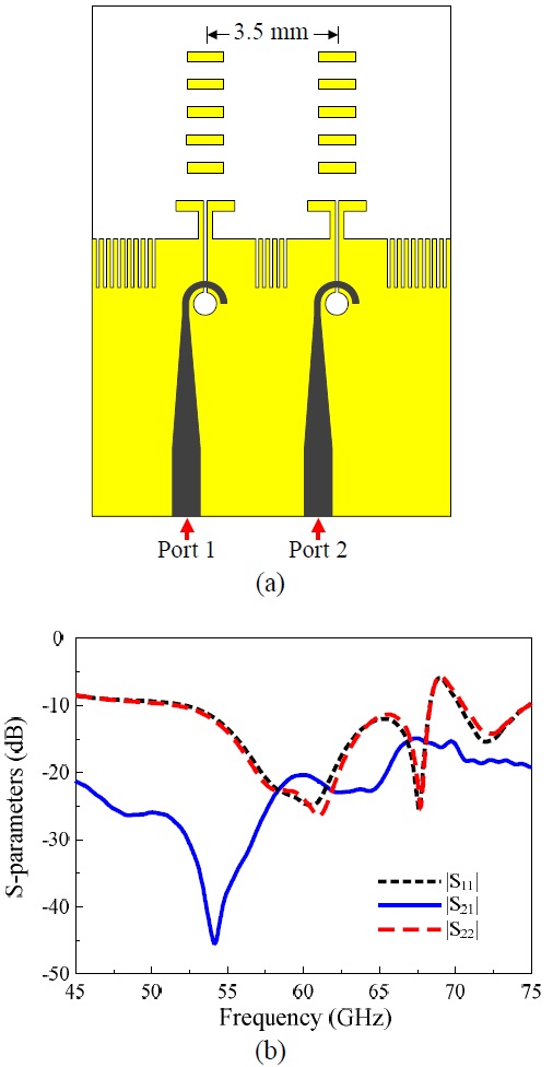
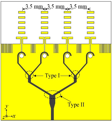
    We used an array, as shown in Fig. 4(a), to calculate the mutual coupling between two 60-GHz quasi-Yagi antennas with a center-to-center spacing of 3.5 mm (0.7 λ0 at 60 GHz), which was chosen based on compromise between low mutual coupling and moderate spacing. Fig. 4(b) shows the simulated S-parameters of the array. The mutual coupling (|S21|) was less than ―16 dB, while the reflection efficiencies at port 1 (|S11|) and port 2 (|S22|) were less than ―10 dB in the 57 to 66 GHz range. Here, the mutual coupling was determined by the transmission coefficient (S21) between ports 1 and 2 of the array. The proposed antenna worked well as an array with a small coupling effect between the adjacent elements.

       2. Feeding Network

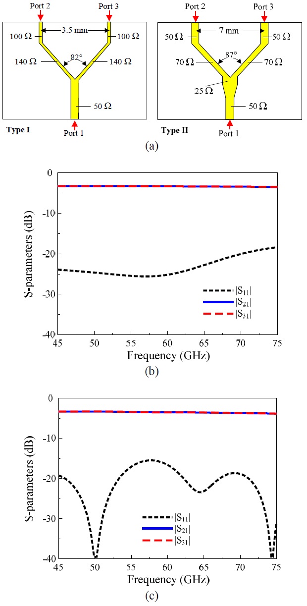
    Two types of Y-junction power dividers in Fig. 5(a) were designed and optimized for the feeding network of 60-GHz quasi-Yagi arrays. The Y-junction power dividers were designed to have an input impedance of 50 Ω. Type I has a characteristic impedance (Z0) of 100-Ω while type II has Z0=50 Ω at the output ports. Fig. 5(b) and (c) show the S-parameters of the power dividers: type I yielded a reflection coefficient (|S11|) of less than ―20 dB at port 1 and transmission coefficients (|S21| or |S31|) from port 1 to port 2 (or port 3) approximately 3.32 dB from 45 GHz to 75 GHz. Alternatively, type II yielded a reflection coefficient (|S11|) and a transmission coefficient (|S21| or |S31|) better than ―16 and 3.36 dB, respectively, at the 45 to 75 GHz range. These results indicate that these power dividers can be widely applied to the 60-GHz bands with an insignificant loss.

       3. Simulation Results

    A four-element array was designed consisting of 60-GHz quasi-Yagi antennas with a center-to-center spacing of 3.5 mm (0.7 λ0 at 60 GHz) between adjacent elements, as shown in Fig. 6. The array was built on both sides of a 15 mm×25 mm Rogers RT/Duroid 5880 substrate and used two type-I and one type-II Y-junction power dividers for the feeding network. The simulated results of the proposed antenna and its array are shown in Figs. 79, including |S11|, radiation patterns, and peak gain and radiation efficiency, respectively. As shown in Fig. 7, all the proposed designs have broad impedance matching bandwidths, which completely covered the 60-GHz bands (57?66 GHz); the single element yielded a |S11|<―10 dB bandwidth of 33.9% (49?69 GHz) while the array had a bandwidth of 26.7% (52?68 GHz).

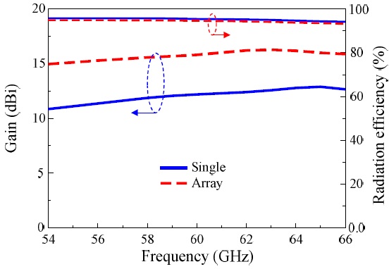
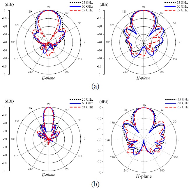
    As shown in Fig. 8, the radiation patterns of the antennas were stable, with a symmetric profile and high frontto-back ratio (>20 dB) across the bandwidth. For the single element, the half power beamwidths (HPBWs) were 36°? 50° and 41°?52° in the E- and H-planes, respectively. Compared with the single element, the array yielded a significantly narrower HPBW in the E-plane patterns, whereas their H-plane patterns were unchanged. For the array, the HPBWs were 26°?32° and 40°?50° in the E- and H-planes, respectively. As shown in Fig. 9, both designs yielded excellent radiation characteristics with high gains (an excess of 12.0 dBi and 15.0 dBi for the single and the array, respectively), small gain variations (±0.5 dB), and high radiation efficiency (>95%) within the 57 to 66 GHz range. These advantages make the proposed antennas good candidates for 60-GHz wireless communication systems.

    Ⅳ. Measurements

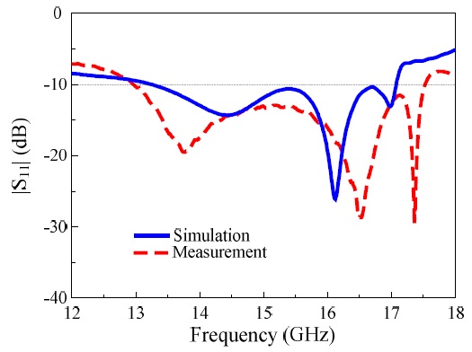
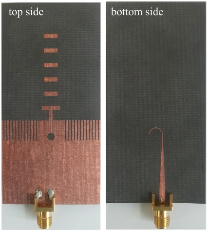
    The features of the proposed antenna were validated, while simultaneously reducing the cost of fabrication, by scaling up all design parameters of the 60-GHz quasi-Yagi antenna to operate at 15 GHz. The 15-GHz single-element antenna was built on both sides of 40 mm×80 mm Rogers RT/Duroid 5880 substrate with a dielectric constant of 2.2, a loss tangent of 0.0023, and copper thicknesses of 17 μm, via standard wet etching technology. The scaled antenna was also simulated by MWS-CST. The optimized design parameters were as follows: Wms=2.4 mm, Lf=20 mm, Ls=8 mm, rc=1.5 mm, rf=2.5 mm, wf=0.4 mm, g=0.2 mm, Lp=8 mm, sp=0.4 mm, wp=0.8 mm, ws=0.8 mm, S1=S2=S3=4 mm, L1=7.2 mm, L2=5.4 mm, wc=1.6 mm, and h=0.7874 mm. An Agilent N5230A network analyzer and a 3.5-mm coaxial calibration standard GCS35M were used for the input impedance measurement of the prototype (Fig. 10). An SMA connector (not included in the simulations) was used as the coaxial-to-microstrip transition in the fabricated sample. Fig. 11 shows a comparison of simulations and measurement for |S11| of the 15-GHz quasi-Yagi antenna, indicating good agreement between the two. The measurement and simulation resulted in |S11|<―10 dB bandwidths of 29.5% (13.0?17.5 GHz) and 25.1% (13.2?17.0 GHz), respectively. The slight difference between the simulation and measurement results could be attributed to misalignment at the transition feed and the effect of the SMA connector.

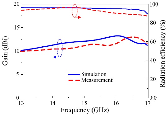
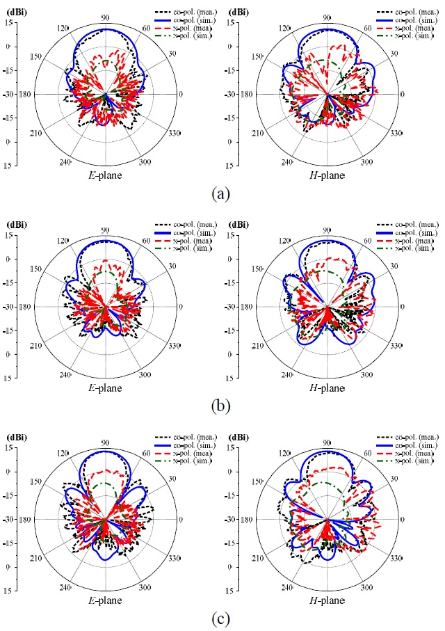
    Another Agilent E8362B network analyzer and a full anechoic chamber were used to measure the 15-GHz antenna’s radiation patterns, as illustrated in Fig. 12. The measurement process used a standard horn antenna for transmitting and the proposed antenna, which was fixed by a foam racking and thin tape, for receivingurement results agreed well with the MWS-CST simulation, and both showed quite symmetric radiation and high front-to-back ratios. At 14 GHz, the measurements resulted in a gain of 11.1 dBi, a front-to-back ratio of 22 dB, and HPBWs of 59° and 65° in the E- and H-planes, respectively. At 15 GHz, the measurements resulted in a gain of 11.3 dBi, a front-to-back ratio of 23.4 dB, and HPBWs of 56° and 57° in the E- and H-planes, respectively. At 16 GHz, the measurements resulted in a gain of 12.9 dBi, a front-to-back ratio of 26 dB, and HPBWs of 48° and 54° in the E and H-planes, respectively. The simulations resulted in a peak gain of 13.23 dBi at 16.0 GHz and a radiation efficiency in excess of 93% within the |S11|<―10 dB bandwidth, while the measurements resulted in a peak gain of 13.2 dBi at 16.5 GHz and a radiation efficiency in excess of 88%, as shown in Fig. 13. The slight difference between the measured and simulated results could be attributed to the effects of the foam racking and the thin tape.

    Ⅴ. Conclusion

    A high-gain broadband quasi-Yagi antenna and its fourelement array have been introduced for 60-GHz wireless communications. A corrugated ground plane was used as a reflector to enhance the gains and consequently achieved minimum gain variation. The four-element array was constructed with a center-to-center spacing of 3.5 mm (0.7 λ0 at 60 GHz) to achieve a low level of mutual coupling (<―16 dB) between the adjacent elements. A scaled-up design of the proposed single-element antenna operating at 15 GHz was designed, fabricated, and tested to simultaneously validate the features of the proposed antenna and reduce the cost of fabrication. The broadband characteristics as well as the high efficiency, high gains, small gain variation, and stable radiation pattern of the quasi-Yagi antenna indicate that it can be widely used in 60-GHz wireless communication systems, as well as in other wideband wireless communications such as automotive radar and switched-beam systems.

참고문헌
  • 1. Smulders P. 2002 "Exploiting the 60 GHz band for local wireless multimedia access: prospects and future directions" [IEEE Communications Magazine] Vol.40 P.140-147 google cross ref
  • 2. Han K., Park Y., Choo H., Park I. 2009 "Broadband CPSfed Yagi-Uda antenna" [Electronics Letters] Vol.45 P.1207-1209 google cross ref
  • 3. Ta S. X., Kim B., Choo H., Park I. 2010 "Slot-line-fed quasi-Yagi antenna" [in Proceedings of the 9th International Symposium on Antennas, Propagation, and EM Theory] P.307-310 google
  • 4. Ta S. X., Kim B., Choo H., Park I. 2012 "Wideband quasi-Yagi antenna fed by microstrip-to-slotline transition" [Microwave and Optical Technology Letters] Vol.54 P.150-153 google cross ref
  • 5. Ta S. X., Kang S., Park I. 2012 "Closely spaced two-element folded-dipole-driven quasi-Yagi array" [Journal of Electromagnetic Engineering and Science] Vol.12 P.254-259 google cross ref
  • 6. Ta S. X., Choo H., Park I. 2012 "Wideband double-dipole Yagi-Uda antenna fed by a microstrip-slot coplanar stripline transition" [Progress in Electromagnetics Research B] Vol.44 P.71-87 google
  • 7. Ta S. X., Park I. 2013 "Wideband double dipole quasi- Yagi antenna using a microstrip-to-slotline transition feed" [Journal of Electromagnetic Engineering and Science] Vol.13 P.22-27 google cross ref
  • 8. Pan B., Li Y., Ponchak G. E., Papapolymerou J., Tentzeris M. M. 2009 "A 60-GHz CPW-fed high-gain and broadband integrated horn antenna" [IEEE Transactions on Antennas and Propagation] Vol.57 P.1050-1056 google cross ref
  • 9. Vettikalladi H., Lafond O., Himdi M. 2009 "High-efficient and high-gain superstrate antenna for 60-GHz indoor communication" [IEEE Antennas and Wireless Propagation Letters] Vol.8 P.1422-1425 google cross ref
  • 10. Pazin L., Leviatan Y. 2010 "A compact 60-GHz tapered slot antenna printed on LCP substrate for WPAN applications" [IEEE Antennas and Wireless Propagation Letters] Vol.9 P.272-275 google cross ref
  • 11. Ohira M., Miura A., Ueba M. 2010 "60-GHz wideband substrate-integrated-waveguide slot array using closely spaced elements for planar multisector antenna" [IEEE Transactions on Antennas and Propagation] Vol.58 P.993-998 google cross ref
  • 12. Suga R., Nakano H., Hirachi Y., Hirokawa J., Ando M. 2010 "Cost-effective 60-GHz antenna package with end-fire radiation for wireless file-transfer system" [IEEE Transactions on Microwave Theory and Techniques] Vol.58 P.3989-3995 google
  • 13. Karim M. F., Guo Y. X., Sun M., Brinkhoff J., Ong L. C., Kang K., Lin F. 2011 "Integration of SiP-Based 60-GHz 4×4 antenna array with CMOS OOK transmitter and LNA" [IEEE Transactions on Microwave Theory and Techniques] Vol.59 P.1869-1878 google cross ref
  • 14. Hsu S. S,, Wei K. C., Hsu C. Y., Chuang H. R. 2008 "A 60-GHz millimeter-wave CPW-fed Yagi antenna fabricated by using 0.18-μm CMOS technology" [IEEE Electron Device Letters] Vol.29 P.625-627 google cross ref
  • 15. Alhalabi R. A., Rebeiz Y. C., Chiou G. M. 2011 "Selfshielded high-efficiency Yagi-Uda antennas for 60 GHz communications" [IEEE Transactions on Antennas and Propagation] Vol.59 P.742-750 google cross ref
  • 16. Kramer O., Djerafi T., Wu K. 2011 "Very small footprint 60 GHz stacked Yagi antenna array" [IEEE Transactions on Antennas and Propagation] Vol.59 P.3204-3210 google cross ref
  • 17. Wu X. Y., Hall P. S. 2010 "Substrate integrated waveguide Yagi-Uda antenna" [Electronics Letters] Vol.46 P.1541-1542 google cross ref
  • 18. Wu X. Y., Akhoondzadeh-Asl L., Hall P. S. 2011 "Printed Yagi-Uda array for on-body communication channels at 60 GHz" [Microwave and Optical Technology Letters] Vol.53 P.2728-2730 google cross ref
  • 19. Stutzman W. L., Thiele G. A. 2012 Antenna Theory and Design google
  • 20. Alhalabi R. A., Rebeiz G. M. 2008 "High-efficiency angled- dipole antennas for millimeter-wave phased array applications" [IEEE Transactions on Antennas and Propagation] Vol.56 P.3136-3141 google cross ref
이미지 / 테이블
  • [ Fig. 1. ]  Geometry of the high-gain broadband quasi-Yagi antenna.
    Geometry of the high-gain broadband quasi-Yagi antenna.
  • [ Fig. 2. ]  (a) |S11| and (b) gain of the antenna with/without a corrugated ground plane.
    (a) |S11| and (b) gain of the antenna with/without a corrugated ground plane.
  • [ Fig. 3. ]  (a) |S11| and (b) gain of the antenna with/without a corrugated ground plane.
    (a) |S11| and (b) gain of the antenna with/without a corrugated ground plane.
  • [ Fig. 4. ]  (a) Quasi-Yagi array and (b) its S-parameters.
    (a) Quasi-Yagi array and (b) its S-parameters.
  • [ Fig. 5. ]  (a) Y-junction power dividers, simulated S-parameters for (b) type I and (c) type II.
    (a) Y-junction power dividers, simulated S-parameters for (b) type I and (c) type II.
  • [ Fig. 6. ]  Four-element quasi-Yagi array.
    Four-element quasi-Yagi array.
  • [ Fig. 7. ]  Simulated |S11| for the 60-GHz quasi-Yagi antenna and its four-element array.
    Simulated |S11| for the 60-GHz quasi-Yagi antenna and its four-element array.
  • [ Fig. 8. ]  (a) Normalized total radiation patterns of the 60- GHz quasi-Yagi antenna and (b) its four-element array.
    (a) Normalized total radiation patterns of the 60- GHz quasi-Yagi antenna and (b) its four-element array.
  • [ Fig. 9. ]  Simulated peak gain and radiation efficiency as a function of the frequency for the 60-GHz quasi-Yagi antenna and its four-element array.
    Simulated peak gain and radiation efficiency as a function of the frequency for the 60-GHz quasi-Yagi antenna and its four-element array.
  • [ Fig. 10. ]  Fabricated sample of the 15-GHz quasi-Yagi antenna.
    Fabricated sample of the 15-GHz quasi-Yagi antenna.
  • [ Fig. 11. ]  Comparison between simulated and measured |S11| of the 15-GHz quasi-Yagi antenna.
    Comparison between simulated and measured |S11| of the 15-GHz quasi-Yagi antenna.
  • [ Fig. 12. ]  Radiation patterns of the 15-GHz quasi-Yagi antenna at (a) 14, (b) 15, and (c) 16 GHz.
    Radiation patterns of the 15-GHz quasi-Yagi antenna at (a) 14, (b) 15, and (c) 16 GHz.
  • [ Fig. 13. ]  Gain and radiation efficiency of the 15-GHz quasi-Yagi antenna.
    Gain and radiation efficiency of the 15-GHz quasi-Yagi antenna.
(우)06579 서울시 서초구 반포대로 201(반포동)
Tel. 02-537-6389 | Fax. 02-590-0571 | 문의 : oak2014@korea.kr
Copyright(c) National Library of Korea. All rights reserved.