Many researchers are currently investigating magnetically coupled wireless power transfer (WPT) systems. A conventional WPT system consists of two main resonators for the transmitter and receiver, which operate at the same resonance frequency [1-3]. This system, however, has a limitation on the distance between transmitter and receiver for achieving high WPT efficiency. This limitation can be overcome by using some resonators as relays between the two main resonators [4]. The WPT system is then composed of multiple n resonators, which can achieve a higher WPT efficiency than a conventional WPT system can at the same distance. This system is well analyzed in [5] with respect to the general circuit model and the maximum efficiency with a matched load. However, the general maximum efficiency equation of a WPT system with multiple n resonators described in [5] becomes complicated when analyzing the type of system normally utilized for practical applications.
This paper proposes a new analysis method for the WPT system with multiple n resonators. The method simplifies the entire WPT system into a single two port network expressed by an ABCD matrix. The general maximum efficiency equation of the WPT system with multiple n resonators can then be obtained with elements of the ABCD matrix. This equation provides a much more convenient way to obtain the maximum efficiency and the optimum placement of the asymmetrical relays for the best utilization. The general maximum efficiency equation and the method of the optimum placement of the asymmetrical relays are verified by a full wave simulation of ANSYS HFSS (high frequency structural simulator).
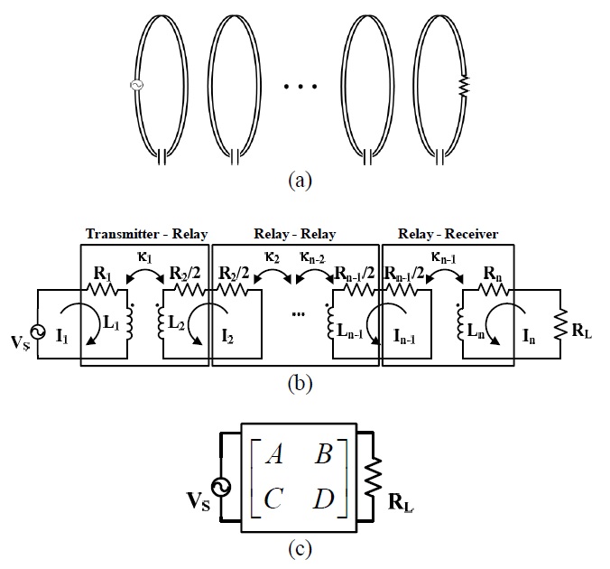
The schematic diagram of a WPT system with multiple n resonators is shown in Fig. 1(a). The non-adjacent coupling coefficient is ignored since it is very small in a practical WPT system with the relays. Thus, the WPT system with multiple n resonators can be considered as n―1 parts of two-port networks connected in series, as shown in Fig. 1(b). Two-port networks have three types of connections: transmitter-relay, relay-relay, and relay- receiver. The system in Fig. 1(b) can then be represented as the single two-port network shown in Fig. 1(c) by the matrix multiplication of ABCD matrices. The maximum efficiency equation in [1] can be adapted for this single equivalent two-port network system because the WPT system with two resonators is also a single two-port network. RL at the end of the circuits in Fig. 1(b) and (c) is a matched load required to obtain the maximum efficiency of the WPT system. The matched load RL can be connected to the receiver either directly or indirectly by inductive coupling with the feeding loop. When the load impedance ZL is connected through the feeding loop, RL can be expressed with the elements of a feeding loop as:
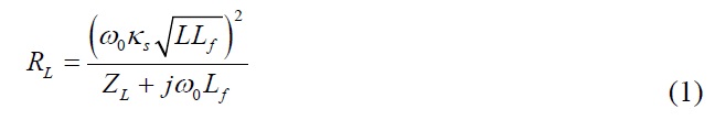
where κs is a coupling coefficient between a feeding loop and the receiver, L is the inductance of receiver, and Lf is the inductance of a feeding loop.
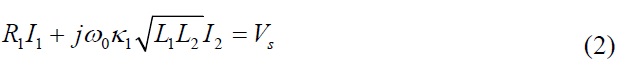
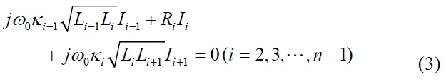
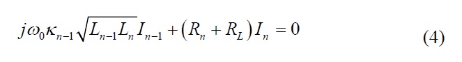
In order to obtain ABCD matrices for three types of two-port networks shown in Fig. 1(b), the circuit equations of a WPT system are needed. When the system operates at the resonance frequency (f=f0), the circuit equations derived from Fig. 1(b) are the following equations:
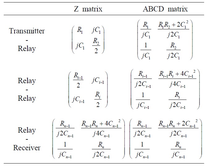
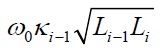
Then, Z matrices of each two-port network are obtained by (2)―(4), and they can be transformed into ABCD matrices [6] following Table 1, where Ci―1 is
(i=2, 3, …, n), and κi―1 is the coupling coefficient between i-1-th resonator and i-th resonator. The single ABCD matrix of the WPT system with multiple n resonators can then be obtained. Finally, the system is equivalent to a WPT system with two resonators.
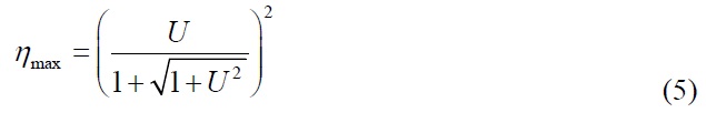
The maximum efficiency (ηmax) equation of the WPT system with two resonators can be applied to the WPT system with multiple n resonators:
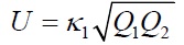
where
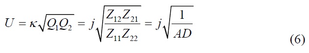
is the figure of merit of a WPT system with two resonators, and Qi=ωoLi /Ri (i=1, 2) is the quality factor of each resonator [1]. The figure of merit U can also be written in terms of elements of the Z matrix and ABCD matrix:
where Zij (i=1, 2 and j=1, 2) is the element of the Z matrix, and A and D are the elements of the ABCD matrix of the WPT system with 2 resonators. The figure of merit U in terms of the elements of ABCD matrix can be applied to a WPT system with multiple n relays using the elements of its single ABCD matrix and it is renamed U'.
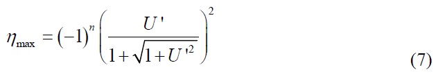
The Eq. (5), ηmax, should also be modified to make a general maximum efficiency equation because Eq. (5) is suitable only for a WPT system with two resonators. The WPT systems with multiple n resonators are classified into two types of systems by the phase difference of the current on the receiving resonator. The phase difference is π/2 between the odd and even numbers of resonators. Thus, the modification of phase for power is j2, which is multiplied in Eq. (5) when the number of resonators is odd. Finally, the general maximum efficiency equation of a WPT system with multiple n resonators is given by:
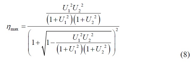
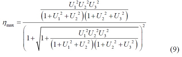
As an example, the maximum efficiency equations of WPT systems with three and four resonators derived by (6) and (7) are represented as:
where Ui―12=κi―12Qi―1Qi (i=2, 3, …, n) is the square of figure of merit between i-1-th resonator and i-th resonator. Qi=ω0Li /Ri is the quality factor of i-th resonator. The matched load RL is also expressed with the elements of ABCD matrix.
The maximum efficiency of a WPT system with multiple n resonators and the matched load RL can then be obtained by the elements of the single equivalent ABCD matrix for the system, (6), (7), and (10). These equations provide a much simpler form than those in [5].
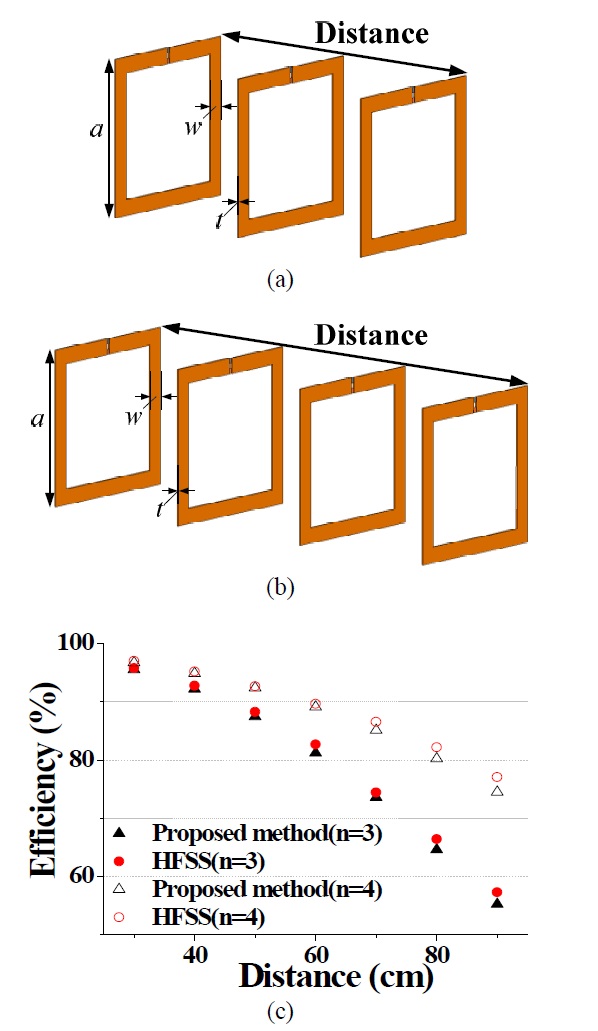
The maximum efficiencies calculated by Eq. (7) are compared with those simulated by ANSYS HFSS, as shown in Fig. 2. The systems operate at 6.78 MHz and have three and four identical resonators, as shown in Fig. 2(a) and (b), respectively. The square resonators [7] used for this system have the following dimensions: a=20 cm, w=2 cm, t=0.2 cm, and C=1,498 pF, and the material of resonators is assigned as copper. The total distance of both systems is changed from 30 to 90 cm. The resonators in the WPT system are equally spaced and have Qi of 950, and the coupling coefficient κi is found from even and odd mode analysis at each corresponding distance between two adjacent resonators [1]. In Fig. 2(c), the efficiencies obtained by two different methods agree well, indicating the validation of the derived equations. However, small differences appear as the distance increases due to the non-adjacent coupling. As the distance gets progressively longer, the difference between the adjacent and non-adjacent coupling coefficient become smaller and, thus, the non-adjacent coupling coefficient has a much stronger influence on the efficiency.
The optimum placement of a WPT system with the asymmetrical relay resonators can also be found with (7). When the WPT system has different sizes of resonators or more than 2 relays, the maximum efficiency will be determined not by the equal spacing but by the optimum placement. The optimum placement should be found by observing the maximum efficiencies at the various placements. These can be easily obtained by calculating (7) with respect to different placements. The optimum placement can then be found from the peak value of the calculation from (7).
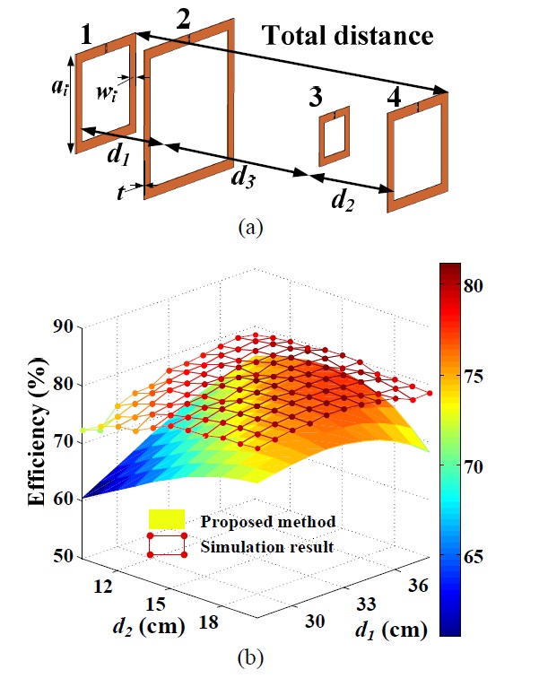
This method is verified by constructing the WPT system with four resonators shown in Fig. 3(a). The system operates at 6.78 MHz and has four square resonators, as shown in Fig. 3(a). Each resonator has Q1=Q4 of 878, Q2 of 1,004, Q3 of 567, and the adjacent coupling coefficients are changed by the different distances. The square resonators [7], assigned as copper, used for this system have the following dimensions: a1=a4=20 cm, a2=30 cm, a3=10 cm; w1=w2=w4=2 cm, w3=1.5 cm; t=0.2 cm; and C1=C4=1,467 pF, C2=804 pF, C3=3,860 pF. The total distance between the transmitter and receiver is 75 cm. The optimum distance of d1 and d2 should be determined to obtain the maximum efficiency. The maximum efficiencies calculated using Eq. (7) are compared with those simulated by ANSYS HFSS, as shown in Fig. 3(b), changing d1 and d2 from 28 to 38 cm and from 10 to 20 cm, respectively. The results from calculation and simulation are obtained at every 1 cm. The coupling coefficients used for calculated maximum efficiencies are calculated from the field calculation of HZ in [8]. The maximum efficiencies and the optimum placement of the WPT system for the verification can then be found from simulation and calculation. The optimum placement is found at d1=34 cm, d2=16 cm with the efficiency of 81.17% from the simulation and at d1=37 cm, d2=15 cm with the efficiency of 77.3% from the calculation. The results show that the tendency for variation in both methods agrees well, despite the small difference caused by the non-adjacent coupling. Thus, the maximum efficiency and the optimum placement can be found quite simply using the proposed calculation.
A simple method to obtain the maximum efficiency of a WPT system with multiple n resonators is presented in this paper. This method is based on ABCD matrices and allows the WPT system with multiple n resonators to be transformed into a single two-port network system. The general maximum efficiency equation of a WPT system with multiple n resonators is derived using the ABCD matrix and is verified by a full wave simulation. This equation is also applied to a WPT system with asymmetrical relays for placement of the relays for the maximum efficiency. The method of optimum placement is also verified by a full wave simulation. The results indicate that our method can be extended to analyze WPT systems with asymmetrical relay resonators.