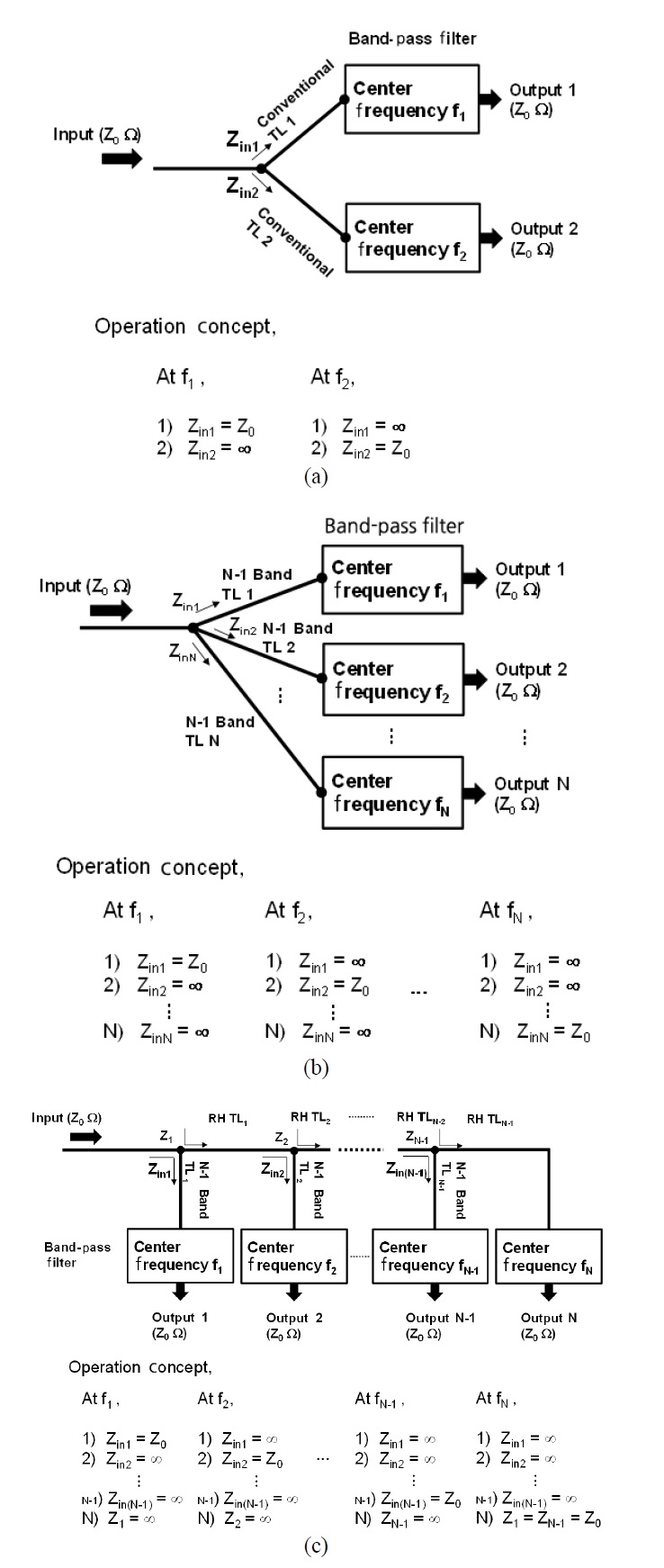
Many modern communication systems are required to handle multiple frequency bands. If a base station for a mobile phone can deal with two or three communication standards, the price of its construction will be lowered with concomitant benefits for customers. Multiband is already intrinsic to cell phone designs for handling cellular, global positioning system (GPS), and WiFi bands. In order to support such multiband systems, a multiplexer is necessary if one antenna covers all the designated spectra and thus becomes an essential component. For multiplexers, many design concepts have been investigated and categorized by star junction type and manifold junction type [1-3]. The first star junction type multiplexer is based on synthesizing singly terminated channel filters [4]. After one decade, another method to synthesize doubly terminated filters for star junction type multiplexers was proposed [5]. In the recent approach [6], a general polynomial model is used for filters, and filters are connected with a complex load. The rapid development of manifold junction type multiplexers was caused by the advent of satellite communication systems [7]. In the initial stage, the analytic approach to design the filters, having proper interaction with other filters on the same manifold, was investigated [8]. However, recent manifold junction type multiplexers are mostly designed with optimization methods with the increased computer power [9]. In both star junction and manifold junction type multiplexers, modification of filters and a complex optimization process are generally required. However, the use of a commercial filter without modification, and a simple multiplexer design method are occasionally necessary for a system designer. The simplest multiplexer satisfying such demand is shown in Fig. 1(a). The diplexer is made of two isolation circuits, and each isolation circuit consists of a conventional righthanded transmission line (RH TL) connected to a filter. An isolation circuit isolates itself from the input port at the center frequency of the other channel. Hence the signal passes through one isolation circuit while it is rejected by the other. This procedure cannot be extended simply to a multiplexer containing three or more channels. Since a conventional TL can provide one phase response at a target frequency, an isolation circuit can be designed to have the isolation characteristic at only one frequency.
If a TL can have a multiple phase property, it can realize a multiband isolation circuit and result in a channel extension of the multiplexer based on isolation circuits. This characteristic has been found in a metamaterial TL. A composite right/left-handed (CRLH) metamaterial TL has a dual-band characteristic [10]. A double-Lorentz (DL) TL has six parameters, and it satisfies six conditions for a tri-band characteristic [11].
In this paper, two types of multiplexers based on isolation circuits are presented. One consists of isolation circuits using same type of TLs, and it can be categorized as the star junction type. On the other hand, the other type uses both RH TLs and multiband TLs for making isolation circuits, and its junction shape is similar to a manifold junction. First, the concepts of multiplexers are explained, and the theory for designing an isolation circuit is investigated. The simulated and measured results of the proposed multiplexers are also provided.
Ⅱ. Concept of Proposed Multiplexer
The diplexer shown in Fig. 1(a) is the starting point for a multiplexer based on isolation circuits. If it is necessary to increase one more channel, an additional isolation circuit can be connected to the junction point like shown in Fig. 1(b), and each circuit should have opencircuit input impedance at the passing frequencies of other circuits [12]. For satisfying this condition, a CRLH TL having dual band characteristic is necessary. In a similar manner, a four-channel multiplexer or a quadruplexer can be realized by connecting four tri-band isolation circuits composed of DL TLs having tri-band characteristic [13].
In the concept of a star junction multiplexer, all isolation circuits are composed with same type of TL. For example, a star junction triplexer is composed with three CRLH TLs followed by three filters. The multiplexer shown in Fig. 1(c) also consists of multiband TLs and filters for multiband isolation circuits. However, one special isolation circuit composed with RH TLs connecting with a filter exists in this type of multiplexers [14,15]. This special isolation circuit also has multiband characteristic. The mechanism is as follows: 1) at frequency
In the diagrams of Fig. 1, the frequencies from
Ⅲ. Theory for Isolation Circuit Design
The method to determine a proper phase response of a TL for an isolation circuit and the theory of a multiband metamaterial TL are discussed in this section.
1. Required Phase Response for Isolation Circuit
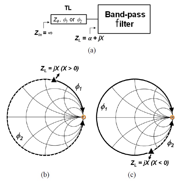
Fig. 2(a) represents an isolation circuit comprising a TL connected to a filter. For simplicity, a case dealing with only one phase is considered. In Fig. 2(b) and (c), each triangle on the Smith chart shows an input impedance of a filter at target frequency to be isolated. In both cases, the real part of the impedance (
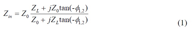
Since the input impedance of the circuit
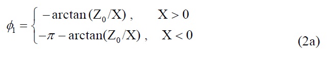
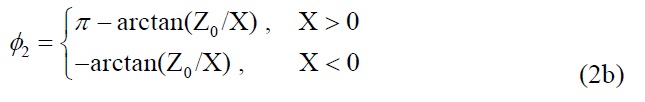
These equations can be simplified to a more general form:

where
2. Multiband Transmission Lines
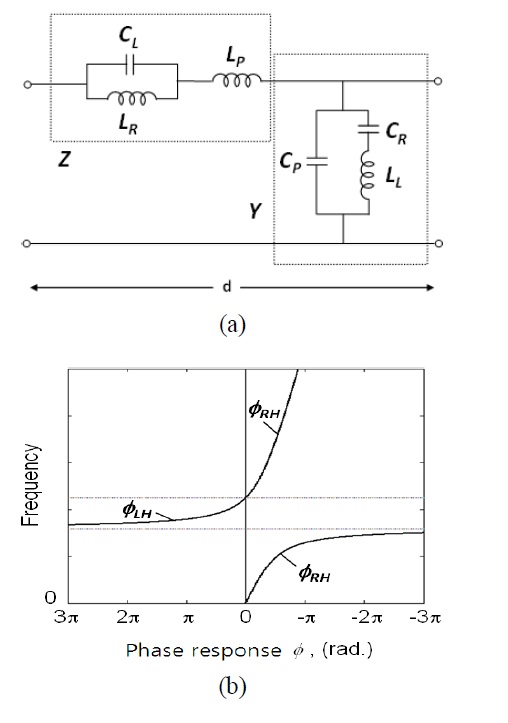
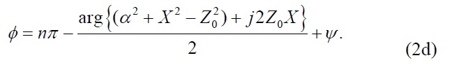
The circuit parameters of a conventional RH TL are series inductance and shunt capacitance. This structure has a linear phase response, and only a RH phase shift or phase delay exists. However, the dual structure of a RH TL or LH TL, of which the circuit parameters are series capacitance and shunt inductance, has a nonlinear phase response, and only a LH phase response or phase advance is supported. Because of a parasitic RH TL, a pure LH TL does not exist in the real world, and a combination of a RH TL and a LH TL, a CRLH TL, has been actively investigated [17]. Fig. 3 shows the circuit model and phase response of a CRLH TL. A CRLH TL shows interesting characteristics in the balanced condition, where the series resonant and shunt resonant frequencies are equal. In the balanced condition of a CRLH TL, the phase response and characteristic impedance are simply represented as,
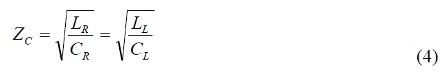
where
A dual-CRLH (D-CRLH) TL has not only the dual characteristics of a CRLH TL but also has the dual structure of a CRLH TL, which has the parallel LC in series branch and series LC in shunt branch [18]. A DL TL is a combination of a D-CRLH TL and a parasitic RH TL, of which circuit parameters are series inductance (
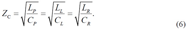
The phase response and characteristic impedance of a balanced DL TL are presented as (5) and (6), respectively [19].
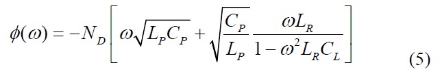
where
In order to verify the design concepts, star junction type multiplexers and manifold junction type multiplexers are designed and fabricated. A RT/Duroid 5870 substrate (
1. Star Junction Type Multiplexers
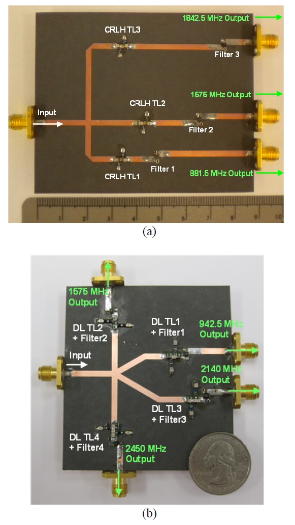
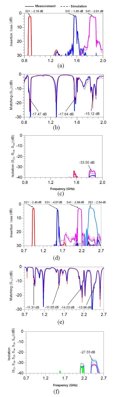
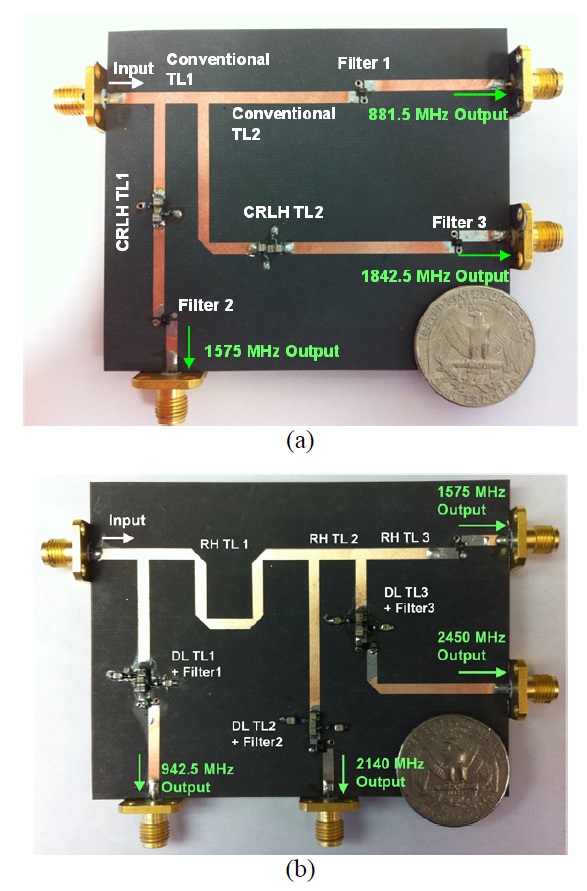
The triplexer based on dual-band isolation circuits is shown in Fig. 5(a). Because of using commercial filters, this triplexer has smaller size than the previous work [12]. The center frequencies of commercial filters are 881.5, 1,575, and 1,842.5 MHz, and each isolation circuit allows signal path at the center frequency of its filter. However, it rejects signal at two operating frequencies of other isolation circuits. For designing CRLH TLs used on dual-band isolation circuits, two target input impedances of each filter are necessary and they are represented in Table 1. After calculating required two phases from two input impedances with (2c) or (2d), the circuit parameters of each CRLH TL can be solved from (3) and (4). The results are summarized in Table 1. For a CRLH TL, lumped elements and microstrip lines are used. A LH part of a CRLH TL was realized using lumped elements whereas a microstrip line was used for a RH TL part. Fig. 6(a)-(c) show the simulated and measured results of the triplexer. Fig. 6(a) shows the insertion losses, which are less than 2.2 dB. Fig. 6(b) shows the return losses better than 15.1 dB, and the isolation is greater than 33.5 dB in Fig. 6(c).
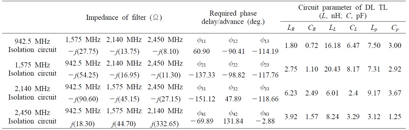
Fig. 5(b) shows the fabricated quadruplexer based on tri-band isolation circuits [13]. The center frequencies are 942.5, 1,575, 2,140, and 2,450 MHz. In a manner similar to that of a dual-band isolation circuit, a DL TL for a tri-band isolation circuit can be designed by getting required phases from input impedances of a filter used on the isolation circuit. Then, circuit parameters of the DL TL are solved from (5) and (6) with the required phase responses and corresponding frequencies. Table 2 shows the input impedances of each filter, the required phase responses, and the circuit parameters of the DL TL satisfying tri-band isolation characteristic. A D-CRLH part of a DL TL was realized using lumped elements while a microstrip line was used for a RH TL part. The simulated and measured results of the quadruplexer are shown in Fig. 6(d)-(f). The worst case of insertion losses shown in Fig. 6(d) is 4.07 dB. This result can be improved by further adjusting the reactance of lumped elements. Insertion losses of other output ports are less than 2.9 dB. Fig. 6(e) shows the return losses larger than 11.3 dB, and the isolation is larger than 27.5 dB in Fig. 6(f).
2. Manifold Junction Type Multiplexers
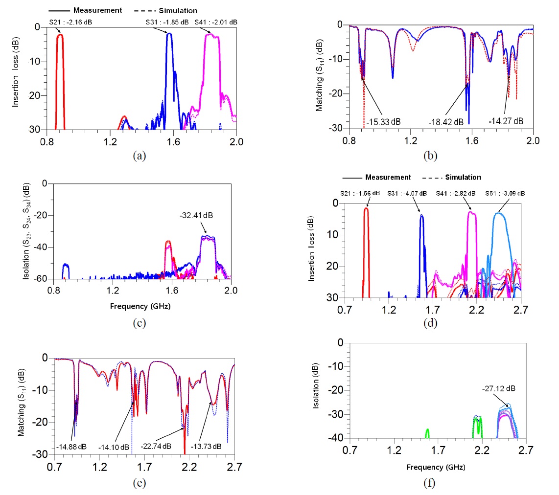
Fig. 7(a) shows the picture of the manifold junction triplexer based on dual-band isolation circuits [14]. Its center frequencies are 881.5, 1,575, and 1,842.5 MHz. The design process of a dual-band isolation circuit based on a CRLH TL is same with that of the star junction triplexer shown in previous section. However, the special isolation circuit based on RH TLs has different operation concept and design method. At 1,575 MHz, the combined phase response of RH TL1 and RH TL2 should satisfy the condition that the input impedance of the special isolation circuit (consisting of two RH TLs and 881.5 MHz filter) is infinite. Similarly, the phase response of RH TL2 should be determined having open condition with the filter at 1,842.5 MHz. Table 3 shows the summary of designed isolation circuits. Fig. 8(a)- (c) show the simulated and measured results of the triplexer. The insertion losses shown in Fig. 8(a) are less than 2.1 dB. Fig. 8(b) shows the return losses better than 14.3 dB, and the isolation is greater than 32.4 dB in Fig. 8(c).
The manifold junction quadruplexer based on tri-band isolation circuits is shown in Fig. 7(b) [15]. The design process is similar with the triplexer case, except that the quadruplexer uses DL TLs and three RH TLs instead of two RH TLs. Table 4 shows the design summary of the quadruplexer. Fig. 8(d)-(f) show the simulated and measured results of the quadruplexer, and simulation results are well matched with measured results. Fig. 8(d) shows the insertion losses, which are less than 4.1 dB. Fig. 8(e) shows that the return losses are better than 13.7 dB, and the isolation is greater than 27.1 dB as shown in Fig. 8(f).
[Table 1.] Design summary of the star junction triplexer
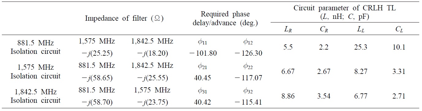
Design summary of the star junction triplexer
Multiplexers based on isolation circuits are presented. The concepts, theories, and design processes have been explained to help the reader design and fabricate proposed multiplexers. These multiplexers have significant advantages. A straightforward and easy design process and the freedom to choose any filters without modification are attractive to a system designer. In this paper, two different types of triplexers and two types of quadruplexers are designed and fabricated. The measured results of each multiplexer show good agreement with the simulation results.
[Table 2.] Design summary of the star junction quadruplexer

Design summary of the star junction quadruplexer
[Table 3.] Design summary of the manifold junction triplexer
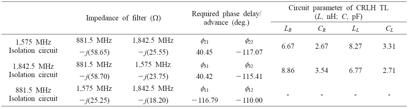
Design summary of the manifold junction triplexer
[Table 4.] Design summary of the manifold junction quadruplexer
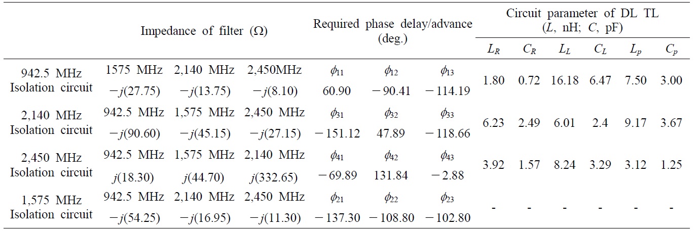
Design summary of the manifold junction quadruplexer


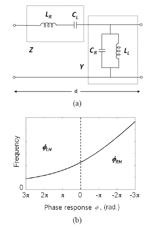
![(a) Circuit model of a double-Lorentz transmission line (DL TL) unit cell and (b) phase response of a DL TL in the balanced case. Source [13], reproduced by permission of ⓒ 2012 EuMA.](http://oak.go.kr/repository/journal/12473/E1ELAT_2013_v13n3_141_f004.jpg)
![Fabricated star-junction multiplexers based on isolation circuits: (a) triplexer and (b) quadruplexer. (b) is from [13], reproduced by permission of ⓒ 2012 EuMA.](http://oak.go.kr/repository/journal/12473/E1ELAT_2013_v13n3_141_f005.jpg)
![The star-junction triplexer results: (a) insertion loss, (b) matching at port 1, and (c) isolation. The starjunction quadruplexer results: (d) insertion loss, (e) matching at port 1, and (f) isolation. (d), (e), and (f) are from [13], reproduced by permission of ⓒ 2012 EuMA.](http://oak.go.kr/repository/journal/12473/E1ELAT_2013_v13n3_141_f006.jpg)
![Fabricated manifold-junction multiplexers based on isolation circuits: (a) triplexer and (b) quadruplexer. (a) is from [14], reproduced by permission of ⓒ 2012 IEEE. (b) is from [15].](http://oak.go.kr/repository/journal/12473/E1ELAT_2013_v13n3_141_f007.jpg)
![The manifold junction triplexer results: (a) insertion loss, (b) matching at port 1, and (c) isolation. The manifold junction quadruplexer results: (d) insertion loss, (e) matching at port 1, and (f) isolation. (a), (b), and (c) are from [14], reproduced by permission of ⓒ 2012 IEEE. (d), (e), and (f) are from [15].](http://oak.go.kr/repository/journal/12473/E1ELAT_2013_v13n3_141_f008.jpg)