This paper introduces a new design for a Rotman lens that has been proposed to minimize its size and provide a suitable design for a compact beamforming system. The size reduction is realized by minimizing the length of the transition structures, which are positioned between the lens body and the connecting lines. The proposed structure is much shorter than a conventional transition structure, which is a tapered line in general. As a result, a 45% size reduction can be achieved by using the proposed transition structure, compared to a typical Rotman lens with linearly tapered lines. Therefore, the proposed Rotman lens will be suitable for compact beamforming systems.
A Rotman lens, first proposed by Rotman and Turner [1], is a kind of planar lens in which a wave is guided along constrained paths based upon the design equations. It can generate multiple beams with phase relationships that are determined from the path length of the wave passing through the lens. Its advantages are easy fabrication, low cost, light weight, wide bandwidth, and the simultaneous availability of many beams. It can have low aberrations in a wide scanning angle because there are three perfect focal points. In addition, it is able to decide the number and direction of beams for the desired shape within the scanning angle. Thus, for 50 years it has been widely used in various areas, especially in military applications [2].
The most recent version of the Rotman lens is a compact design for commercial applications. For this reason, much research has focused on the various types of compact Rotman lenses. A simple method to reduce the lens size is to design the Rotman lens in millimeter wave band [3-5]. Fuchs and Nussler [3] proposed a compact Rotman lens feeding a 10-element linear array at 94 GHz using conventional waveguide technology. Another approach for reducing the size of beamformers involves reduction of the length of delay lines between the lens body and the antenna array. Song et al. [6] fabricated a Rotman lens on a low temperature co-fired ceramic (LTCC) substrate, aiming for 60 GHz system-in-package (SiP) applications. He introduced air cavities around the transmission line, which could lower the effective permittivity of the line. With those lines, the Rotman lens can satisfy the phase conditions for an antenna array with reduced delay lines. A similar method was realized by Cheng et al. [7], who designed a Rotman lens based on a substrate-integrated-waveguide (SIW) and controlled the phase of delay lines by changing the width of the SIW. Previously, a two-layer Rotman lens-fed antenna array has been proposed for a compact beamforming system [8]. This method basically reduces total size of the product using a two-folded structure. In addition, this method can minimize the length of delay lines without violating the true time condition. These characteristics are quite useful for a small device, since most Rotman lenses have delay lines that occupy a large area in the system. In some cases, a larger area is required for the delay lines than for the lens body.
Although the previously reported methods are attractive for compact beamforming systems, the degree of size reduction is limited since most of them only focus on reducing the length of the lines. Therefore, the present work proposes a novel method for a compact Rotman lens. The proposed method is able to reduce the size of transition structures between the lens body and the transmission lines. This is quite effective for size reduction because the area for the transition structure can be reduced to less than half. The method and the design process are explained in detail in the following sections.
Ⅱ. New Transition Structure for a Compact Rotman Lens
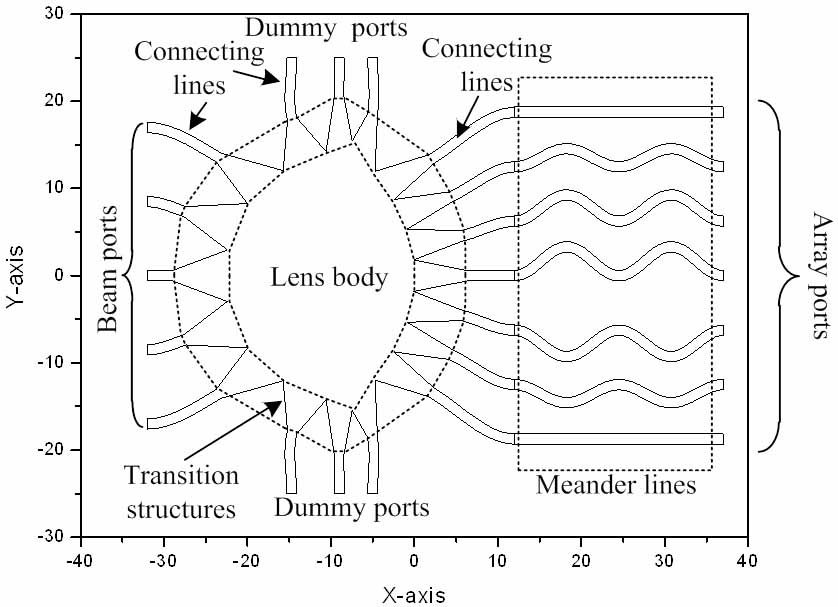
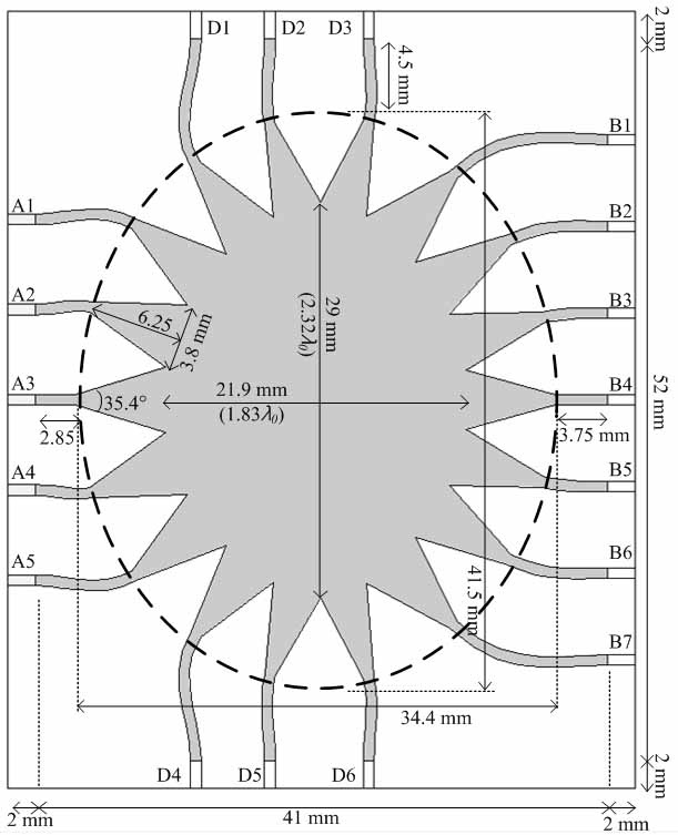
A shape of a typical Rotman lens is shown in Fig. 1. It consists of four parts; the lens body, transition structures, lines, and the antenna array. The shape of the lens body is calculated from the lens equations, with lens parameters such as operating frequency (
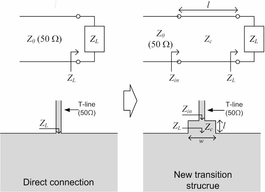
The transition structures are positioned along the periphery of the lens body. They make the transition between the signal lines (typically a 50-Ω line) and the parallel plate region of the lens body. Their major role is power transfer without reflection. In most Rotman lenses, linearly or exponentially tapered lines, which are typically longer than
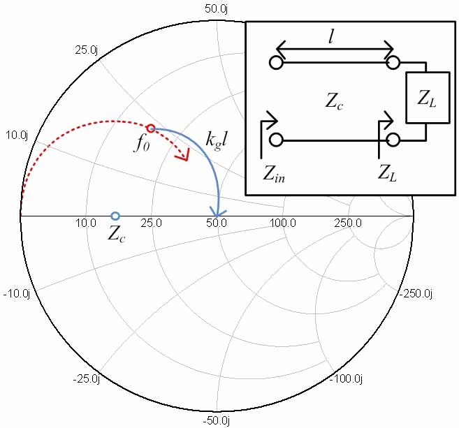
The reason for the large reflection is a mismatch between the line and the parallel plate region. Thus, a simple solution can be found from an impedance matching network, as shown in Fig. 2. The load impedance (
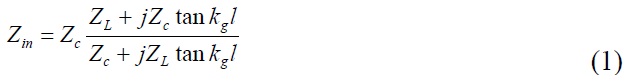
Eq. (1) has only two unknown factors, which are
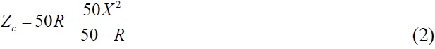
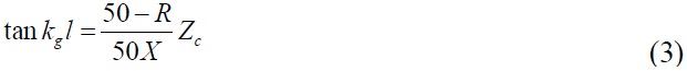
where
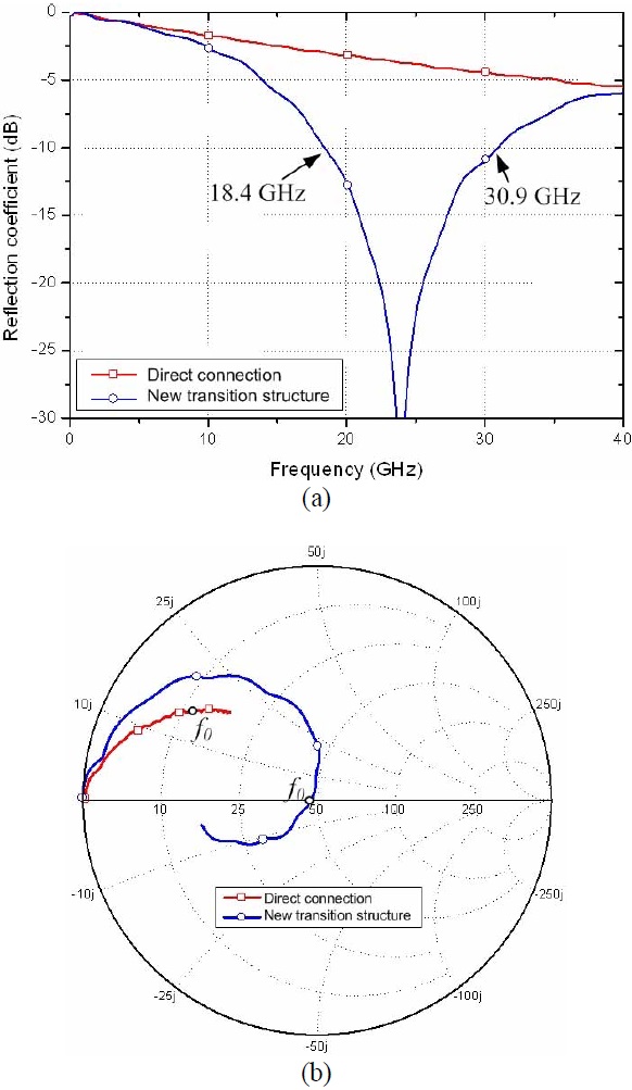
The effectiveness of the proposed method is verified by realizing a new transition structure using both equations and a simulation tool. A microstrip line is selected as a feeding line. The target frequency is 24 GHz. The Taconic TLY-5 (Petersburgh, NY, USA) is used as a substrate whose dielectric constant is 2.2 and height is 0.25 mm. The load impedance is obtained from a fullwave simulation based on the finite-element method (FEM). The simulation setup is described in Fig. 2 (direct connection). In this case, the simulated load impedance (
The proposed structure is simulated with a FEMbased simulation tool. The simulated results differ from the calculated results because the transition structure is not an ideal transmission line. Thus, the length and width are tuned to compensate the differences and the final results are
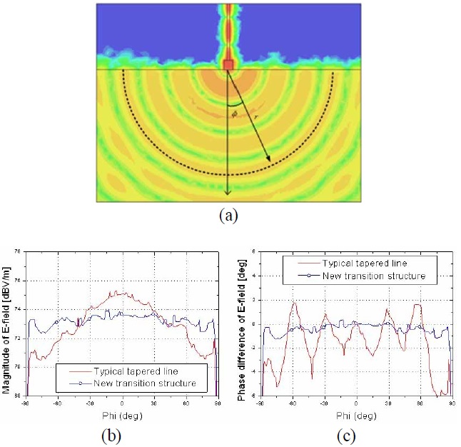
The radiation performance of the proposed transition structure is also studied in the parallel plate region. The distribution of the E-field at 24 GHz is shown in Fig. 5(a). It shows that the E-field fed from the transmission line radiates well into the parallel plate region. The magnitude and phase of a cylindrically radiated field is tested along the dotted circular line presented in Fig. 5(a). The radius (
Ⅲ. Design of a Rotman Lens with the Proposed New Transition Structure
A novel transition structure was proposed and studied in the previous section. In this section, a Rotman lens is designed with the proposed transition to verify its performance and size reduction. Taconic TLY-5 (
Before designing the Rotman lens with the proposed transition structure, a conventional Rotman lens is designed as a reference. It has 5 beam ports, 7 array ports, and 6 dummy ports. The center frequency is 24 GHz, and the band of interest is from 22 GHz to 26 GHz. The distance between antenna elements is a half wavelength in free space (
The size of the lens body with the tapered lines is checked by assuming that the area that includes the lens body and the tapered lines is an ellipse, as presented in Fig. 6. Since the shape and length of the lines are varied in accordance with the positions of the other components, this area is a crucial factor for the size. The equation for the area of an ellipse is
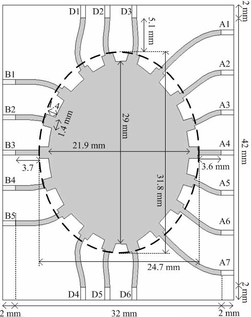
A compact Rotman lens with the proposed new transition structure is then designed, as presented in Fig. 7. It has the same lens body as that of the reference Rotman lens, whereas the proposed transition was used instead of the tapered lines. As mentioned in the previous section, the new transition structure is positioned between the lens body and the connecting lines. The area for the lens body and the transition structures is π (24.7×31.8)/4=616.9 mm2 which is 55% of the reference Rotman lens in Fig. 6.
Ⅳ. Fabrication and Measurement of the Proposed Rotman Lens
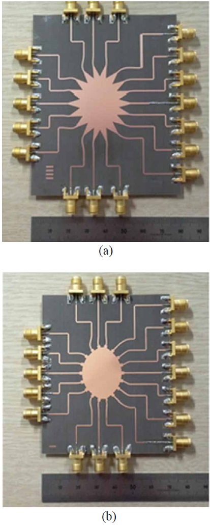
The proposed structure was verified by fabricating and measuring the proposed and the reference Rotman lenses shown in Fig. 8. The lens bodies, as well as the lines, were deliberately patterned on the substrates in a high precision etching process. All ports were connected with high performance SMA connectors. Although the design of the lens body and the tapered lines were fixed, the transmission lines were extended to have enough space between two adjacent SMA connectors. The length and shape of the extended lines were designed to be the same in both Rotman lenses to assure the same effect. The two-port scattering parameters were then measured by a network analyzer (HP8722D; Agilent Technologies, Palo Alto, CA, USA) from 22 GHz to 26 GHz.
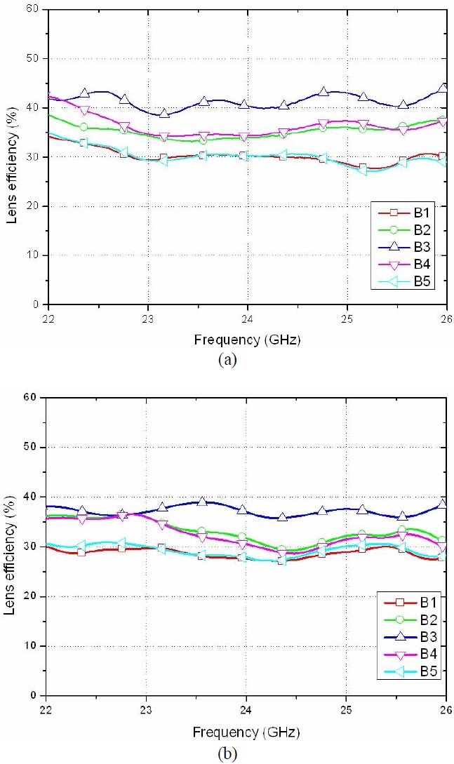
The lens efficiency is the ratio of the input power from a beam port to the gathered power at all array ports. It is the most important factor in lens performance. The lens efficiencies are obtained from the measured two-port scattering parameters. The results are plotted in Fig. 9. The lens efficiencies of the proposed structure at 24 GHz are 27.7%, 31.7%, 37.1%, 30.5%, and 27.8%, respectively, whereas those of the reference Rotman lens are 30.3%, 34.0%, 40.4%, 34.4%, and 30.3% respectively. The lens efficiencies of the proposed Rotman lens are slightly lower than those of the reference Rotman lens in all beam ports. The possible reason is that the less directive pattern of the new transition structure, which is plotted in Fig. 5(b), reduces the lens efficiencies. However, the differences are not significant. The maximum difference is observed from B4, at which is 3.9%.
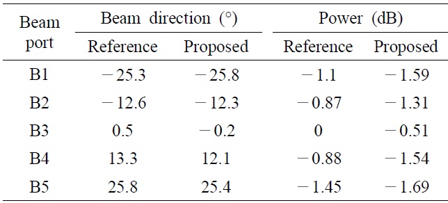
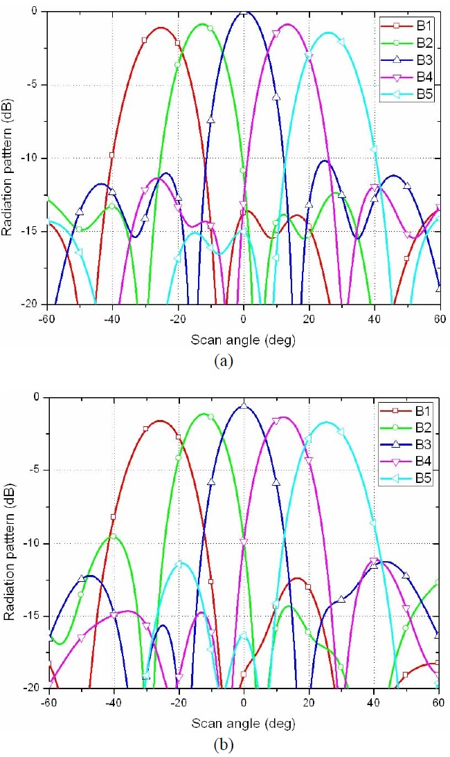
The radiation patterns are synthesized from the measured two-port scattering parameters. The results are plotted in Fig. 10. All beams are normalized to the pattern from B3 of the reference Rotman lens. For a quantitative comparison, the directions and powers of the main beams are summarized in Table 1, which shows that the largest differences of the beam direction and the power are 1.1° and 0.66 dB at B4, respectively. These results indicate that two both types of Rotman lenses have similar performances.
[Table 1.] Comparison the proposed Rotman lens with the reference Rotman lens

Comparison the proposed Rotman lens with the reference Rotman lens
Therefore, the measured results indicate that a Rotman lens with the proposed new transition structures can reduce the total size of a Rotman lens while maintaining the lens performance.
In this work, new transition structures that can replace the tapered line in a Rotman lens have been demonstrated as a novel method to realize a compact Rotman lens. The proposed transition structure is similar to a single-section transformer. With this structure, the connecting line can be matched with the lens body. The width and length are the adjustable parameters. It has smaller size than a typical tapered line, whose length is
The proposed method is verified by the simulation and the measurement. A Rotman lens with the proposed transition structure occupies a smaller area than a conventional tapered Rotman lens. In conclusion, the proposed method can provide a compact design for a Rotman lens with good performance.