Offshore floating structures have so-called moonpool in the centre area for the purpose of drilling, installation of subsea structures, recovery of Remotely-Operated Vehicle (ROV) and divers. However, this vertical opening has an effect on the operating performance of floating offshore structure in the vicinity of moonpool resonance frequency; piston mode and sloshing mode. Experimental study based on model test was carried out. Moonpool resonance of floating offshore structure on fixed condition and motion free condition were investigated. And, the effect of cofferdam which is representative inner structure inside moonpool was examined. Model test results showed that Molin’s theoretical formula can predict moonpool resonance on fixed condition quite accurately. However, motion free condition has higher resonance frequency when it is compared with that of motion fixed. The installation of cofferdam moves resonance frequency to higher region and also generates secondary resonance at lower frequency. Furthermore, it was found that cofferdam was the cause of generating waves in the longitudinal direction when the vessel was in beam sea.
Although world economy has the uncertainty, world energy consumption is continuously increasing due to the growth of the world economy. According to the increase of energy demands, high oil prices are lasting and the market of floating offshore structure continues to grow.
Offshore floating structures have so-called moonpool in the centre area for the purpose of drilling, installation of subsea structures, recovery of ROV and divers. However, this vertical opening has an effect on the operating performance of the floating offshore structure in the vicinity of moonpool resonance frequency; piston mode and sloshing mode.
In the past, Fukuda (1977) carried out empirical research regarding the behavior of ship-shaped floating offshore structure. He observed the flow inside moonpool using the models with circular and sqare shape moonpool and studied the effect to the vessel motion caused by the violent flow inside moonpool.
Recently, Molin (2001) has derived theoretical formulas for piston mode and sloshing mode resonance frequency of moonpool using velocity potential and boundary condition. And, he applied those formulas to a barge type vessel with the moonpool in the center area.
Maisondieu and Ferrant (2003) obtained moonpool resonance frequency from Fast Fourier Transform (FFT) of time history of free surface elevation inside moonpool and it was compared with predicted resonance frequency from theoretical formula. Veer and Tholen (2008) performed resistance test for moonpool of the drillship with the ratio of various length to breadth and studied the correlation between the shape of moonpool and increase of resistance, witnessed the variation of free surface elevation inside moonpool according to the ratio of draft to moonpool breadth.
Meanwhile, Park (2009) carried out the model test in 2D wave flume to find the variation of flow inside moonpool according to the change of breadth of moonpool and the devices for flow reduction and analyzed the model test results. Taylor et al. (2009) investigated viscous effect on the prediction of violent flow inside moonpool from the idea for the difference between potential based prediction results of free surface elevation inside moonpool and the measurements from model test.
Choi et al. (2010) performed flow analysis for the different shape of moonpool using in-house Computational Fluid Dynamics (CFD) code to investigate complex mechanism of violent flow inside moonpool. Through this study, the overturn of free surface due to the cofferdam and forming process of complex flow field were examined regarding the model with cofferdam.
However, previous studies could not address hydrodynamic characteristics of moonpool such as resonance frequency on motion free condition and the shift of moonpool resonance by cofferdam inside moonpool. According to Yang et al. (2012), moonpool resonance can be predicted through motion analysis of floating offshore structure. For example, surge and heave Response Amplitude Operators (RAOs) present peaks at resonance frequency. At this resonance frequency, added mass and damping show nearly singular pattern. He insisted that moonpool resonance is shifted to different frequency region when the vessel has inner structure like cofferdam inside moonpool.
In this study, the followings were investigated based on model test.
(1) Piston mode resonance frequency in fixed condition.
(2) Piston mode resonance frequency in motion free condition.
(3) Shift of moonpool resonance due to cofferdam inside moonpool.
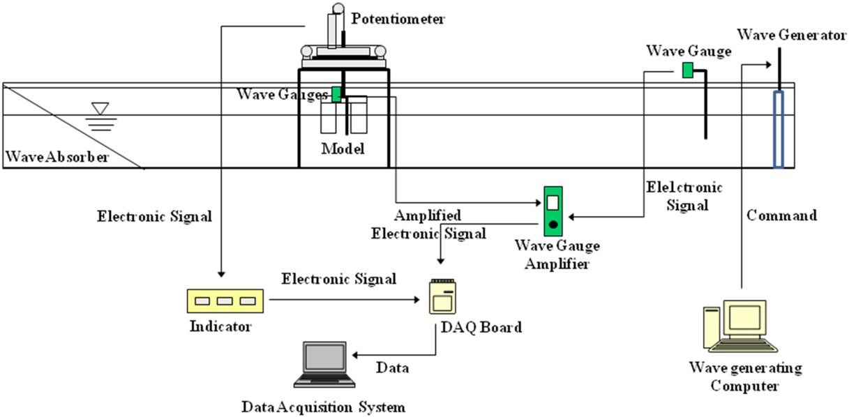
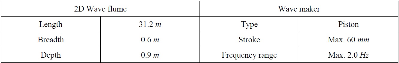
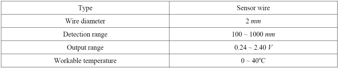
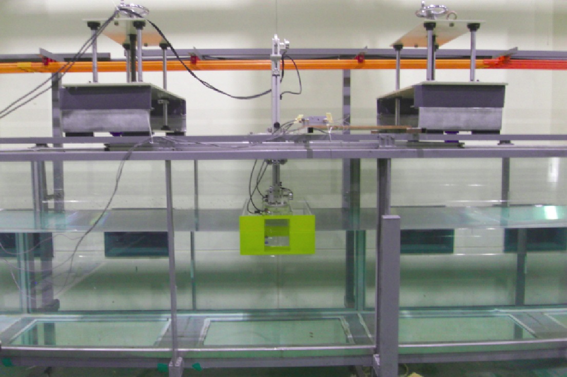
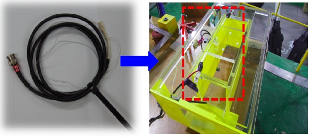
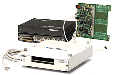
Schematic diagram for model test is shown in Fig. 2. Particular dimensions of 2D wave flume and wave maker are shown in Table 1. Type of wave gauge is described in Table 2. NI data acquisition equipment was used for data acquisition.
[Table 1] Experimental facility.

Experimental facility.
[Table 2] Specification of wave gauge.

Specification of wave gauge.
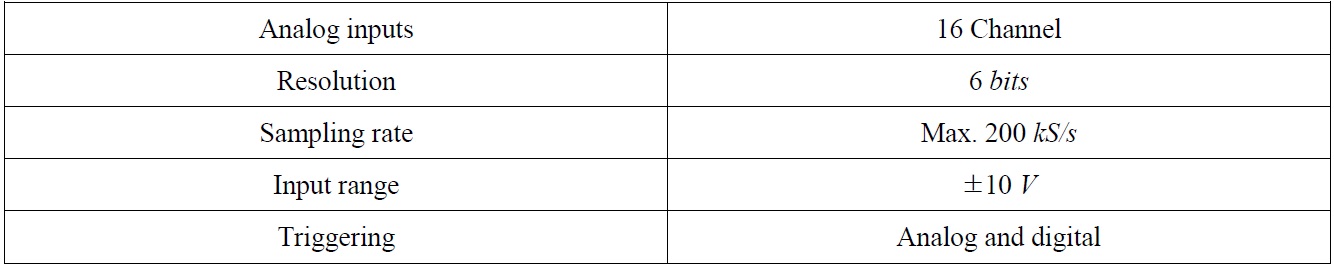
[Table 3] Specification of NI DAQPad-6015 board.

Specification of NI DAQPad-6015 board.
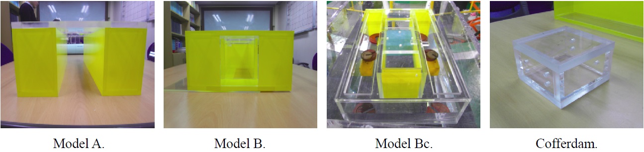
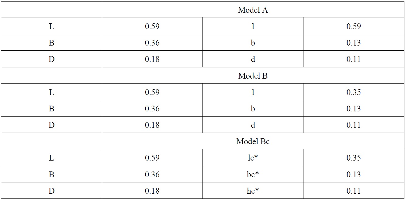
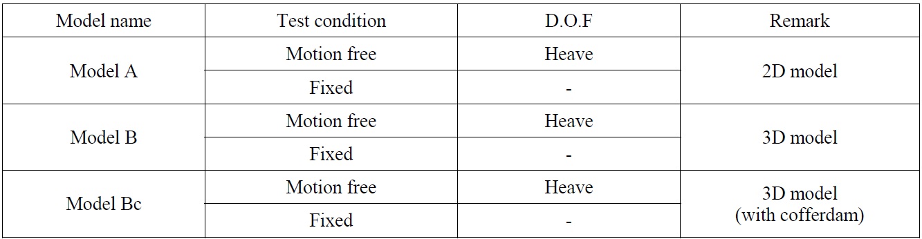
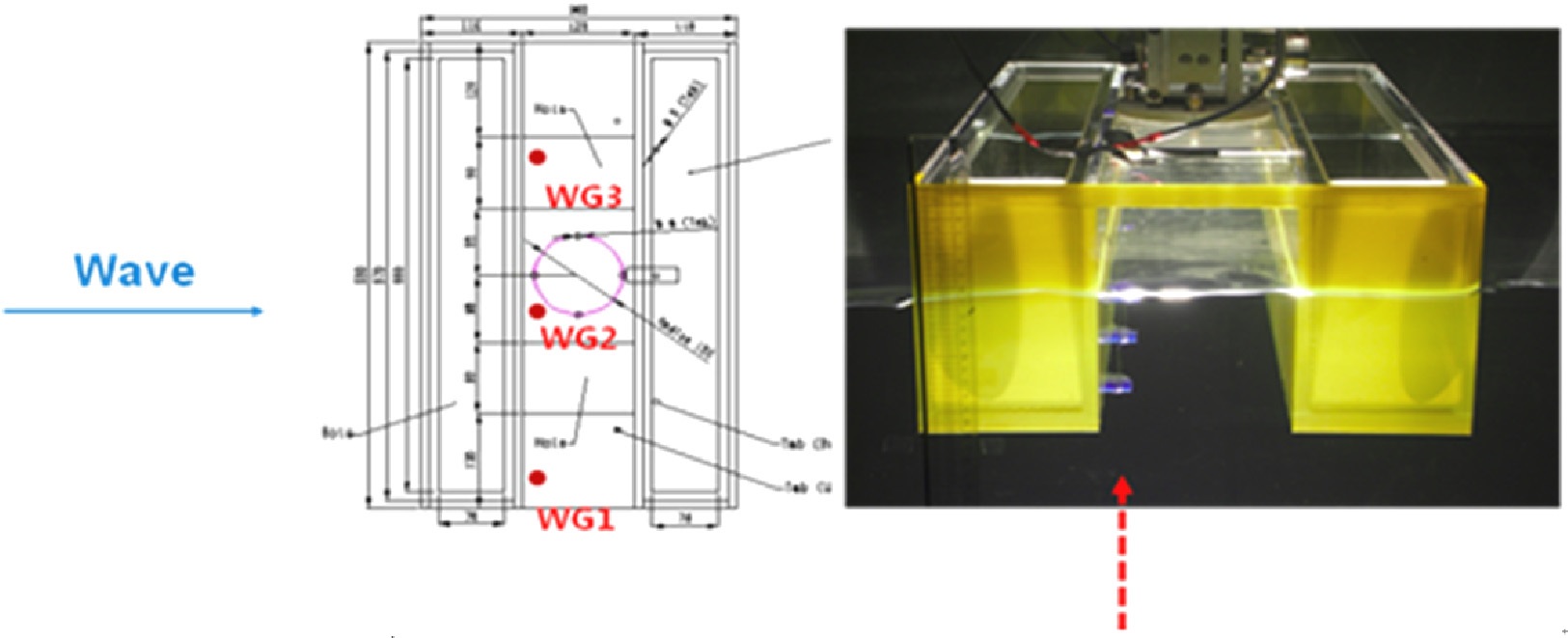
Three models are tested. One is 2D model which has 2D section of vessel in the vicinity of midship section including moonpool. Another is 3D model which has closed moonpool boundary. The other is 3D model with cofferdam. Last one is a typical moonpool shape that modern compact drillship has. Main dimensions of each model are shown in Table 4.
[Table 4] Main dimensions of each model.

Main dimensions of each model.
Model Bc has the same moonpool dimension but box type cofferdam inside moonpool is combined. One vessel model, four wave probes are installed in 2D wave flume.
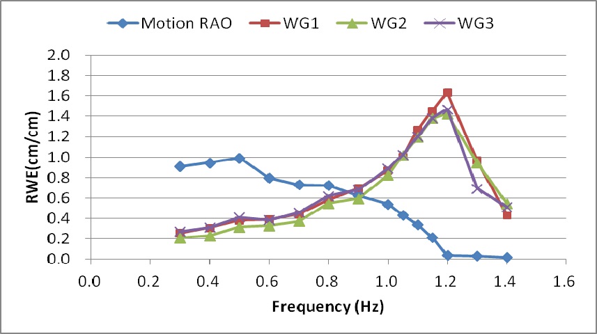
The locations of wave probes are as follows: Wave Gauge 1 (WG1) and WG3 are located near wall of moonpool. WG2 is located in the center of moonpool. Location of wave probes of Model A are illustrated in Fig. 6.
Model test considers fixed condition and motion free condition of the model. Relative water elevation inside moonpool and motion of the vessel are measured based on wave condition. To avoid the effect of coupling with roll motion, heave motion is only released in model test.
WAVE CONDITION AND TEST CONDITION
Wave conditions for model test are summarized in Table 5. Additional wave frequencies are selected around resonance frequency. Test conditions are summarized in Table 6. For each model, fixed condition and motion free condition are considered.
[Table 5] Wave conditions for model test.
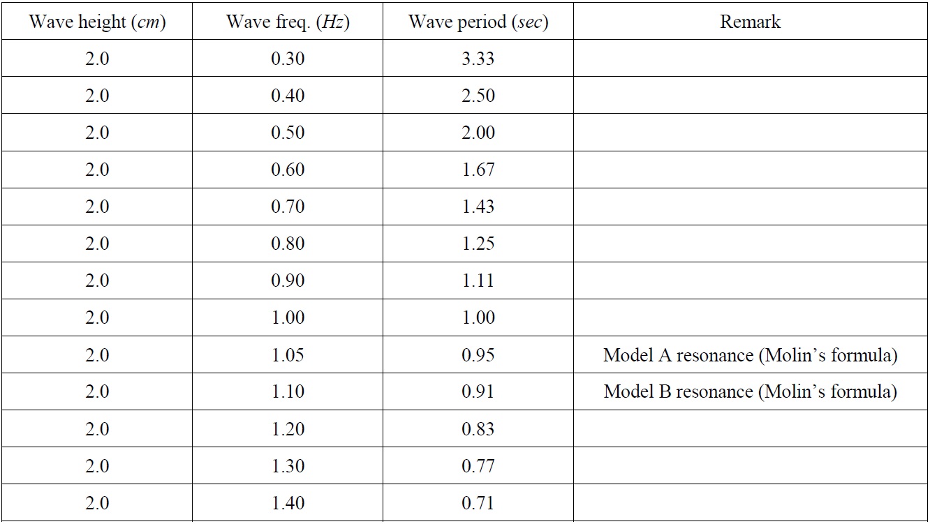
Wave conditions for model test.
[Table 6] Test conditions for model test.

Test conditions for model test.
EXPERIMENTAL RESULTS AND ANALYSIS
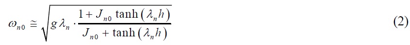
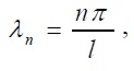
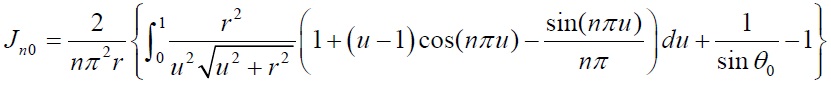
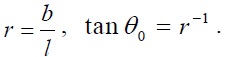
Molin (2001) expressed moonpool resonance frequency of piston mode and sloshing mode as follows respectively:
Piston mode
where
Sloshing mode
where,
where,
>
Wave Gauge Relative Water Elevation (WG RWE) and Motion RAO
The average values of time histories of incident wave and relative water elevation in moonpool were used. Regarding incident wave, measured data without the vessel were used because incident wave is reflected and diffracted by the model in 2D wave flume. And, steady state results of measured data for relative wave elevation and vessel motion were used.
WG RWE and Motion RAO are defined as follows. Piston mode moonpool resonance frequency are summarized in Table 7.

*Relative water elevation in moonpool : distance from baseline of the model to free surface.
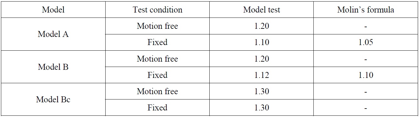
[Table 7] Summary of piston mode moonpool resonance frequencies.

Summary of piston mode moonpool resonance frequencies.
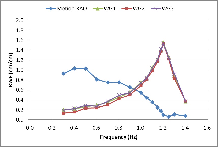
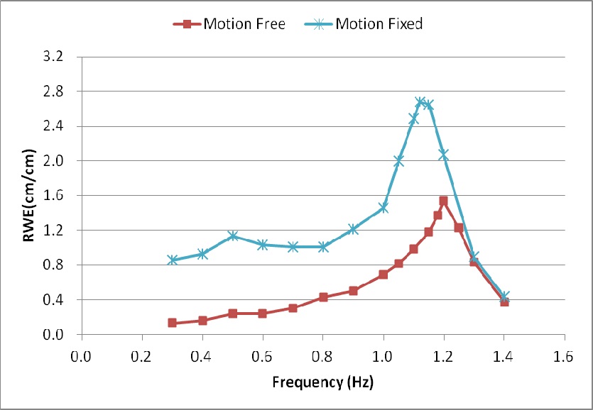
Moonpool resonance of Model A presents 1.20
>
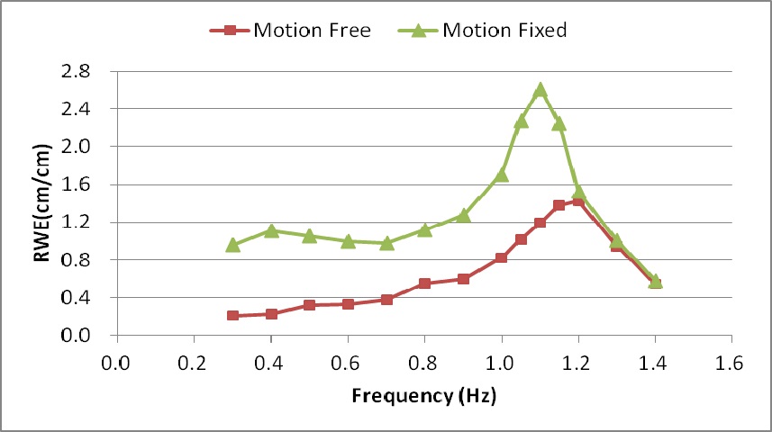
Model A : motion free vs. motion fixed
Moonpool resonances on motion free condition and fixed condition are 1.20
Moonpool resonance of Model B presents 1.20
>
Model B : motion free vs. motion fixed
Moonpool resonance frequency on motion free condition and fixed condition are 1.20
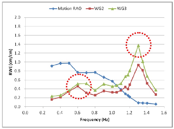
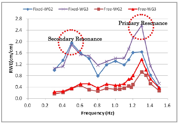
Resonance frequency of Model Bc presents 1.30
>
Model Bc : motion free vs. motion fixed
In case of Model Bc, resonance frequencies on motion free condition and fixed condition present 1.30
>
Cofferdam effect and longitudinal sloshing wave
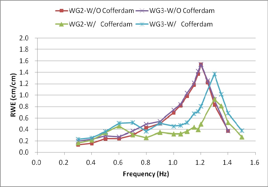
Fig. 14 shows comparison results between without cofferdam and with cofferdam. The model case with cofferdam inside moonpool indicates the shifted resonance frequency compared with the model without cofferdam. And also, cofferdam reduces relative water elevation 11% near wall and 39.6% in the center of moonpool. This means the cofferdam inside moonpool make resonance frequency shifted. In other words, it can be used the cofferdam as the effective design parameter at the initial design stage of offshore vessel. Keeping moonpool resonance frequency away from wave frequency of its design sea state can avoid violent flow in moonpool. Ultimately, operating performance of the vessel can be improved using this design strategy.
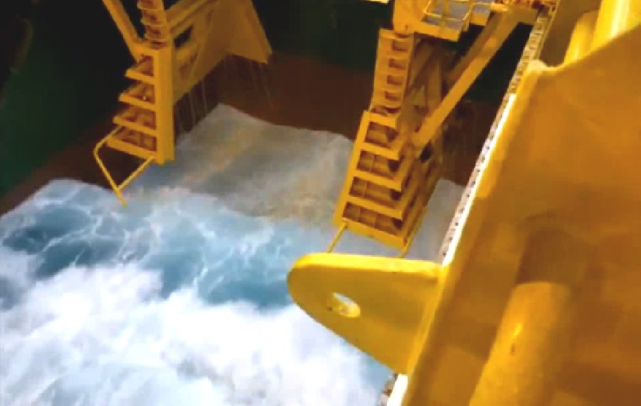
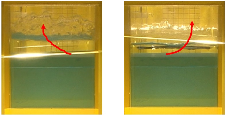
Wave was generated in the longitudinal direction when the vessel was in beam sea. And, the overturn of free surface near at the end of cofferdam was observed through model test. Fig. 15 shows sloshing waves in longitudinal direction. Left photo shows front moonpool wall and right photo shows rear moonpool wall to longitudinal direction of vessel.
Model tests have been performed. Three models are tested and the followings are drawn based on the model test results.
(1) Molin’s formula predicts piston mode frequency quite accurately.
(2) Motion free condition has higher resonance frequency when it is compared with that of motion fixed.
(3) The installation of cofferdams moves resonance frequency to higher region. It also generates secondary resonance at lower frequency.
(4) Cofferdams reduce the water elevation inside of the moonpool.
(5) Cofferdams were the cause of generating waves in the longitudinal direction when the ship was in beam sea.