The hybrid-type mount combines a passive mounting device with active technology, thus representing a new alternative for high-tech facilities, automobiles, ships, and the like. The hybrid type, which can be activated by various types of actuators including hydraulic actuators (Turnip et al., 2009), electromagnetic actuators (Howard et al., 2000; Lee and Lee, 2009) or piezoelectric actuators (Kamada et al., 1997; Choi et al., 2004; Nguyen et al., 2009), is utilized to improve the isolation performance of the passive type. In our previous research (Moon et al., 2010; Nguyen et al., 2008), a 100
This research is focused on a novel hybrid mount capable of supporting a static load of 500
The main technical contribution of this study is to introduce a new hybrid mount which is very effective for vibration control in broadband frequency range. Especially, the new hybrid mount was designed based on military specifications which are normally used for the performance evaluation of the standard resilient passive rubber mounts of US Navy. While the hybrid mount studied in the previous research was a serial-type mount designed for serial connection with the rubber and piezostack actuators, the new hybrid mount was designed as an inertia-type mount in order to generate greater control force. The new hybrid mount consists of a commercial rubber resilient mount, a piezostack actuator, and an inertial mass. The rubber mount is one of the US Navy’s standard resilient mounts (passive type) (Howard et al., 2000). In order to evaluate the various performances of the hybrid mount, several experimental tests were carried out according to military specifications. In addition, control performance based on the concept of vibration transmissibility was tested using a special model capable of simulating the double mounting system. Through a series of experimental tests, it has been confirmed that the hybrid mount delivers good performance against both vibration and shock, making it suitable for use in naval ships.
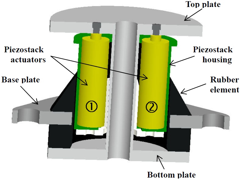
The hybrid mount proposed in this study consists of passive and active elements, with a rubber element serving as the passive element and a piezostack element serving as the active one, following the extended line of the previous research (Moon et al., 2010). The hybrid mount developed in the previous research was composed of a rubber element and two piezostack elements, which were serially connected as shown in Fig. 1. The two piezostack actuators were inserted into the rubber element in order to meet the height constraint. The mount had a natural frequency of 6.3
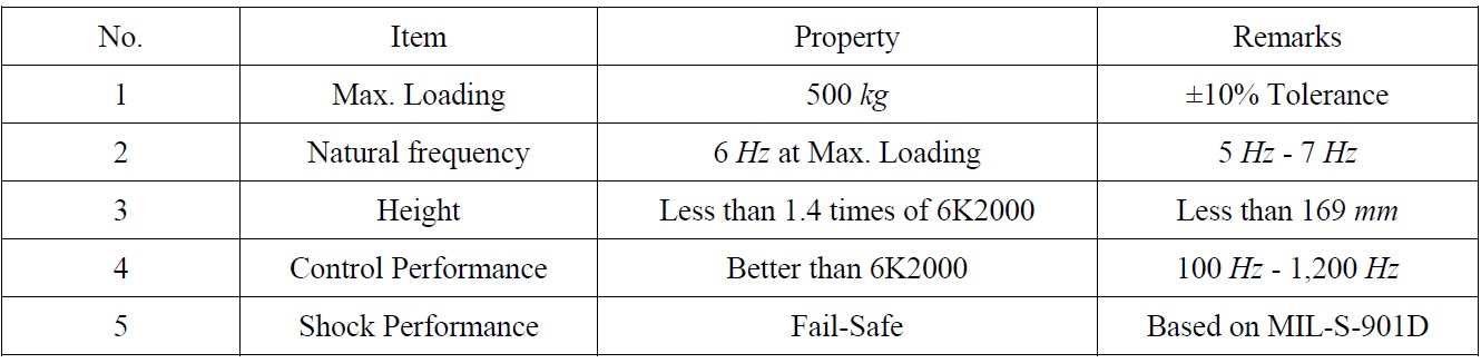
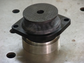
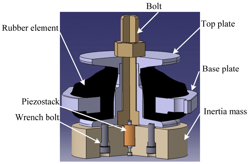
The design requirements of the new hybrid mount are summarized in Table 1. Since the new hybrid mount should have greater static capability than the serial-type hybrid mount, greater control force was required to obtain a good control performance. However, the control force of commercial piezostack actuators is limited in terms of their height and volume, and large piezostack actuators are both rare and extremely expensivee serial-type hybrid mount developed in the previous research was inappropriate for a large hybrid mount, a new inertia-type hybrid mount was proposed, as shown in Fig. 2. The proposed hybrid mount consists of a commercial navy mount (model 6K2000), a piezostack actuator, and an inertial mass. The inertial mass is hung down from the piezostack actuator, and the piezostack actuator is connected to the equipment with a rigid bolting shaft. Although the control force is proportional to the weight of the inertial mass, the height of the inertial mass is restricted to the design requirements given in Table 1.
[Table 1] Design specification of the hybrid mount.

Design specification of the hybrid mount.
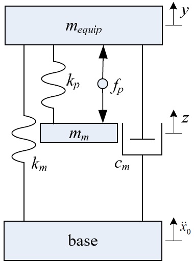
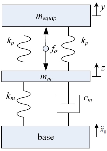
Fig. 3 and Fig. 4 show schematically lumped-mass models of the proposed inertia-type hybrid mount and the serial-type hybrid mount, respectively. The vibration system, consisting of the proposed hybrid mount and equipment, can be modeled as a two degree-of-freedom (2-DOF) system, as shown in Fig. 3. From the model, the governing equations of motion can be derived as follows:


where


where
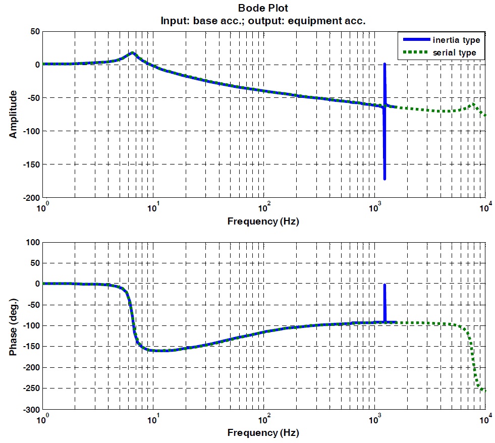
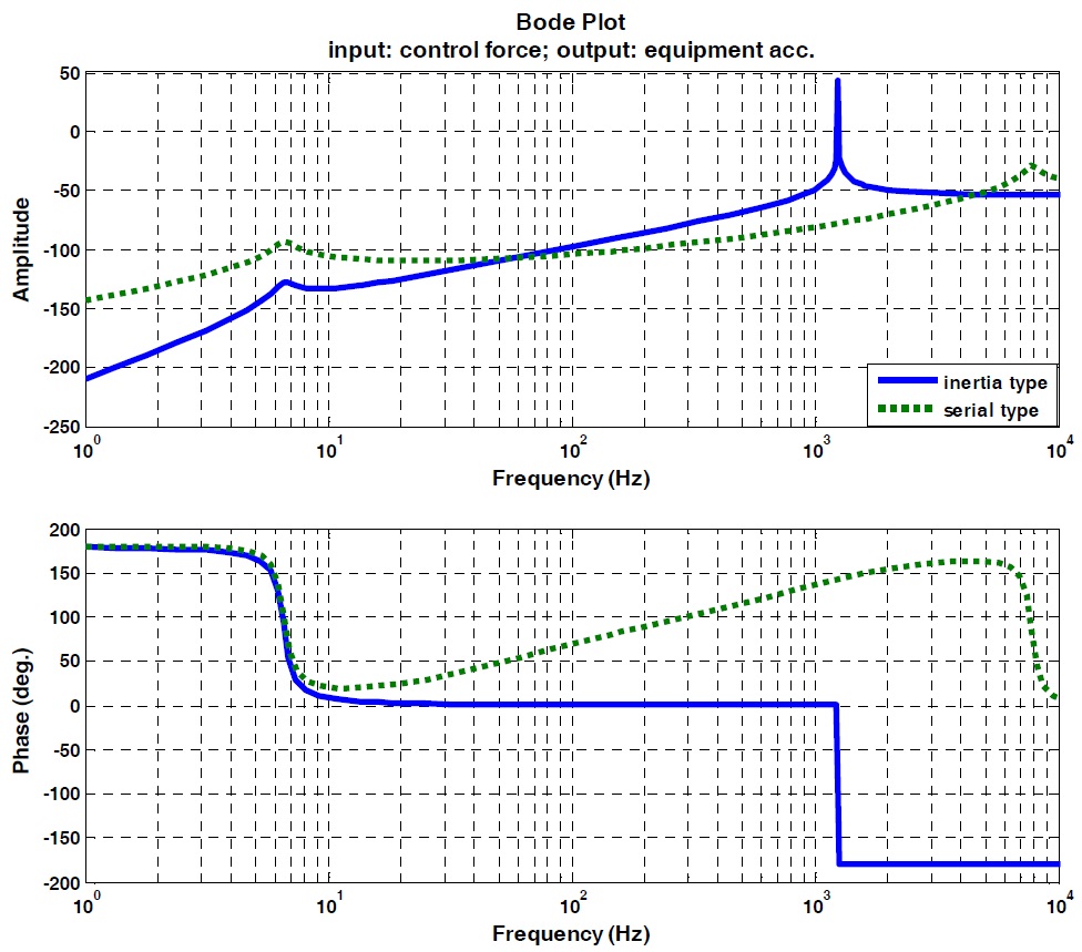
Fig. 5 and Fig. 6 show the Bode plots from base exciting acceleration to equipment acceleration, and from piezostack actuating control force to equipment acceleration, respectively. Both figures were plotted using the results based on Eqs. (1) - (4). As shown in Fig. 5, the two Bode plots have the same characteristics below 1,200
The proposed hybrid mount consists of a commercial navy mount (model: 6K2000 produced by Super Century, Co. (2011)), a piezostack actuator, and an inertial mass. The commercial navy mount developed according to the military specification MILM- 17508F(SH) (1990) was slightly modified in order to connect it with the piezostack actuator using an M8 bolt. It is assumed
that this minor modification would not affect the performance of the mount. The piezostack was purchased from Piezomechaniks GmbH (model: PSt350bp/25/15VS35) (2011). Considering the height constraint included among the design requirements summarized in Table 1, the inertial mass (fabricated from mild steel) was determined to have a weight of 10.8
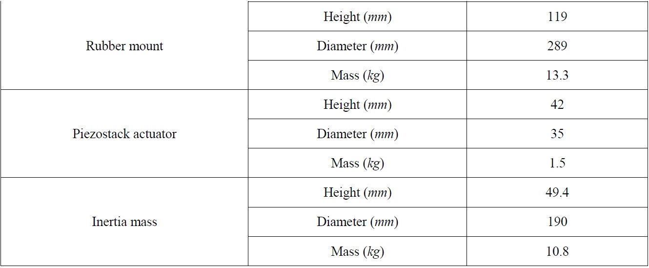
[Table 2] Dimensional specifications of the proposed hybrid mount.

Dimensional specifications of the proposed hybrid mount.
The fabricated hybrid mounts were experimentally tested to confirm the required performance. It is known that there are no specific military specifications for the hybrid mounts for use on naval vessels. As a tough measure, both MIL-M-17185A (SHIPS) and MIL-M-17508F(SH) were optionally applied to the military performance evaluation for the developed hybrid mount, since the hybrid mount was developed based on the resilient 6K2000 mount. The military performance tests included the following: resonant frequency, deflection at rated load, quality of the rubber to metal bond, strength test in the axial direction, strength test in the radial direction, drift test, fatigue test, and shock test. Since these testing items are the same as those used in the previous research (Moon et al., 2010), the test results were only addressed briefly in this paper.
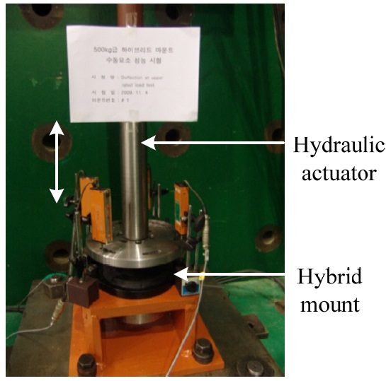
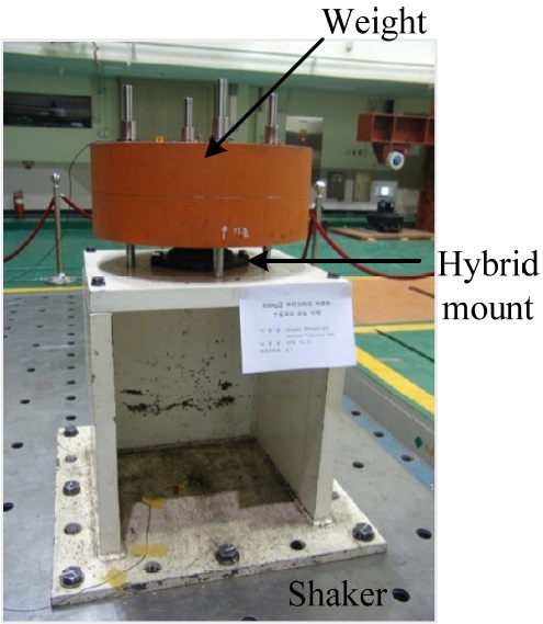
Fig. 8 shows the apparatus used to measure the resonant frequencies of the mount directly. A test weight of 500
MIL-M-17508F(SH) states that the deflections of the hybrid mount, when tested in the axial direction at their respective rated loads, should be within the specified limit of 10.2
MIL-M-17508F(SH) states that mounts should show no breaks, cracks, or tears in the rubber elements, or any evidence of delamination at the rubber to metal bond interfaces. The load on the mounts was increased to two times the upper rated load after recording the degree of deflection under the upper rated load. The mount held twice its upper rated load, and the appearance of the rubber element and of the rubber-to-metal bond was examined to determine conformance. No damage was observed.
>
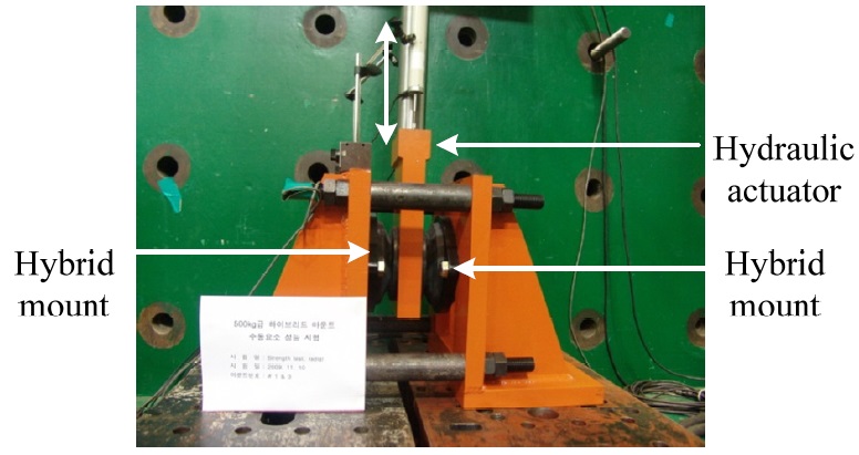
Strength test in the axial direction
MIL-M-17508F(SH) states that mounts, when tested in the axial direction, should not show any separation or break between the parts, nor any permanent deformation of the metal parts in excess of 0.794
>
Strength test in the radial direction
MIL-M-17508F(SH) states that mounts, when tested in the radial direction, should not show any separation or break between the parts nor any permanent deformation of the metal parts in excess of 0.794
The height of the mount was measured one hour after loading and again after 96 hours. The difference in the two readings was taken as the drift of the mount. The drift limit was set at 2.03
Mounts should be able to withstand fatigue loading without showing any signs of failure or deterioration in the rubber element, the rubber to metal bond, or the metal components according to MIL-M-17508F(SH). Each mount was loaded to its upper rated load in the axial direction and subjected to 500,000 cycles of vibration at its natural frequency, with mount deflecttion of ±1.27
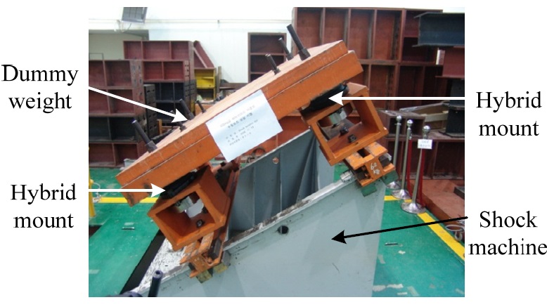
MIL-M-17185(SHIPS) states that the mount should be of such design that under the hammer blows of the applicable shock test. No separation, or break in/or between components of the mount shall occur which will permit the mounted equipment to become free. The natural frequency of the mount after the shock test in the axial and radial direction should not vary more than ±15% from the average resonant frequency. The hybrid mounts were tested four at a time on the medium weight shock test machine. A dummy mass of about 2,000
A filtered-X LMS algorithm is an adaptive filter algorithm, which is suitable for active control application (Widrow and Stearns, 1985; Hakansson et al., 1998). It is a feed-forward control which involves canceling disturbance from the system’s response with the reference input(s). In this study, the algorithm was adapted using the feed-forward signals measured on the dummy weight, which was vibrated by an exciter. Items of shipboard equipment generally have self-exciting sources, and they have steady-state characteristics with constant frequencies. Vibration from the equipment is transmitted to the hull of ship through the foundations of equations - such as the mount, damper, steel block, etc. The feed-forward signal measured can be handled as reference input(s) in the control algorithm. The disturbance - in this case, the vibration on each hybrid mount induced by the vibration of the dummy weight, - would be cancelled by first passing the reference input though a filter whose parameters are adjusted by the LMS algorithm.
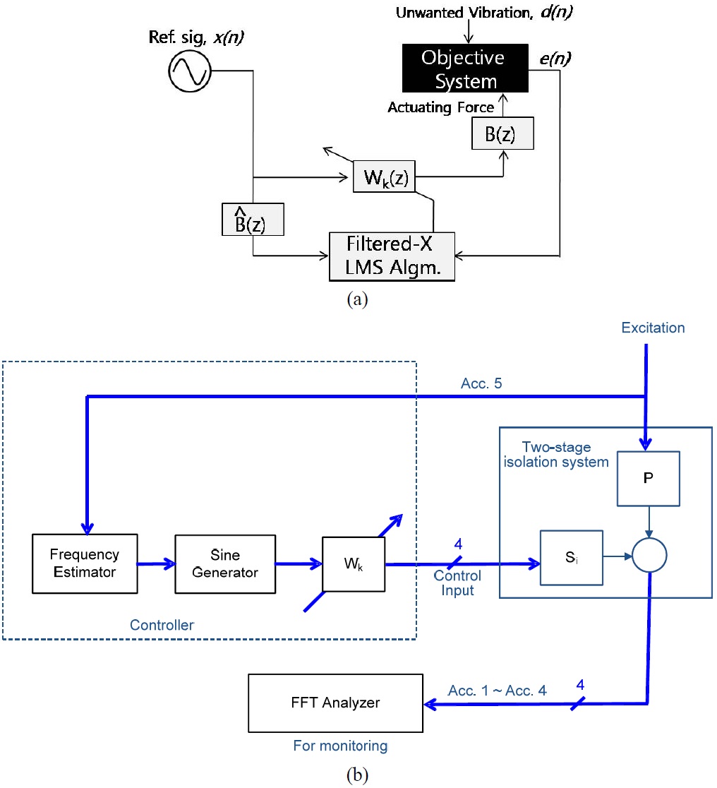
Fig. 12(a) shows the block diagram of the filtered-X algorithm including the elimination of disturbance with an adaptive finite impulse response (FIR) filter controller. The error

where
The adaptive algorithm should have an objective function to minimize the adjustment of the variables used in the function. In this study, the least-mean-square (LMS) of the error was used as an objective function, as described in

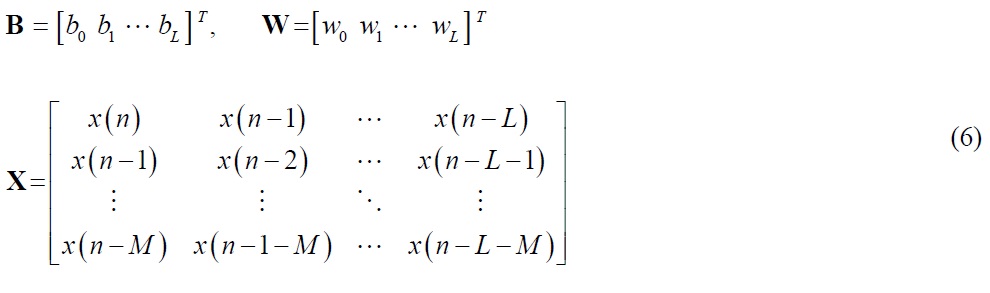
The mean-square error is a quadratic function of W. The adaptive algorithm adjusts the coefficients of FIR filter,

where

As with Eq. (9), the optimal solution, Eq. (8), becomes

In Eq. (10),
Fig. 12(b) shows a block diagram representing the application of the filtered-x LMS algorithm to the hybrid mount system. The measured acceleration signal on the payload was defined as the error signal, and a sine function was used as the reference signal. The order of the FIR filter,
EVALUATION OF CONTROL PERFORMANCE
The evaluation of the active control performance for the hybrid mount was processed based on the vibration transmissibility concept, wherein vibration transmissibility is expressed as follows:
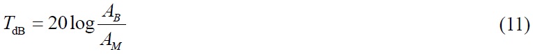
In Eq. (11),
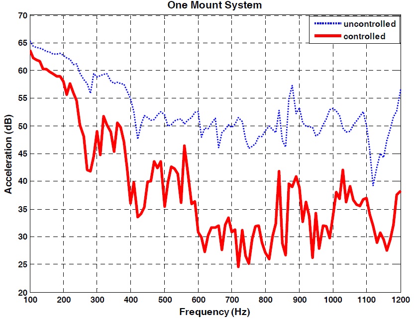
To evaluate the control performance, an experiment in which the excitation ranged from 100
System modeling
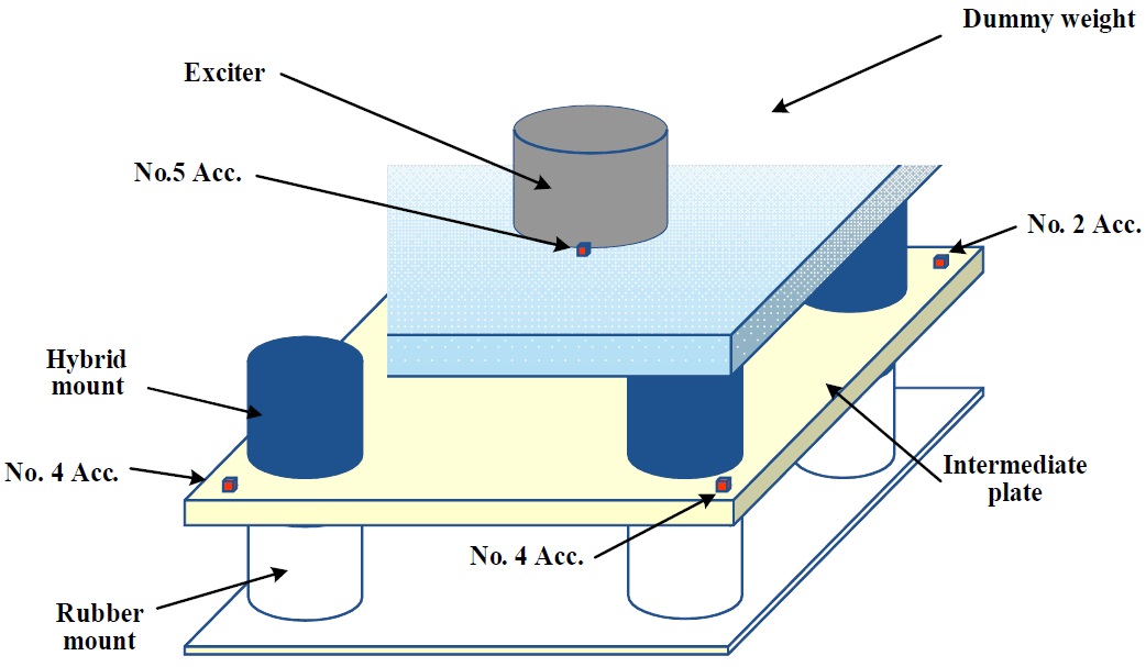
Generally, an isolation system for shipboard equipment consists of four mounts and auxiliary devices. In order to systematically evaluate the active control performance of the proposed hybrid mount, a two-stage isolation system was analytically configured, as shown in Fig. 15. A dummy weight of about 2,000
Fig. 16 presents the mathematical model of the proposed hybrid mount system. The dummy weight and the intermediate plate are assumed as rigid. Each upper mount has an inertial mass of
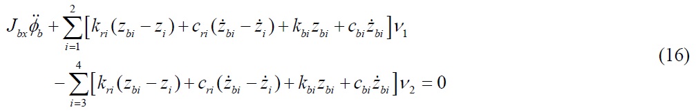
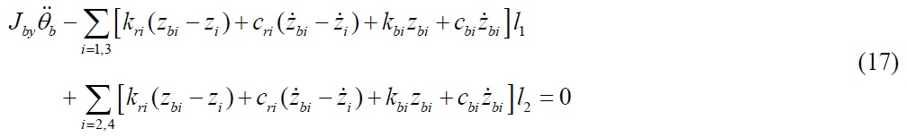
Therefore, the three DOFs - namely, heaving, rolling and pitching - of the two-stage isolation system were considered, and their motions on the dummy weight can be expressed as the following equations:

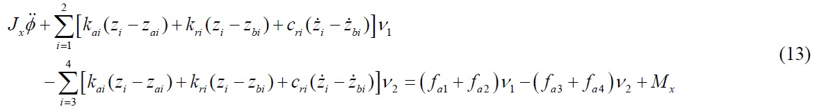
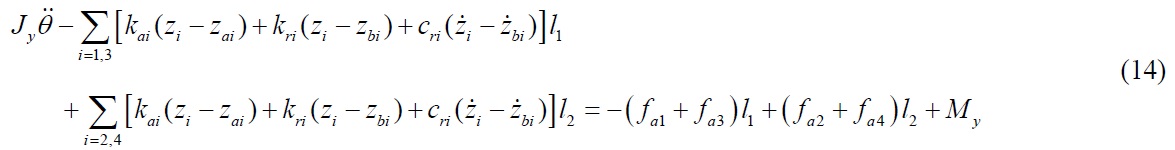
where

where

Because the table plate was rigid, the following equations can be induced according to the geometric condition.
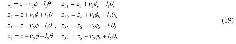
By substituting Eq. (19) into Eqs. (12) - (18), the equation of motions in matrix form can be obtained as follows:
where M, C and K are the mass, damping and stiffness matrices, respectively; fa is the supplemental force vector exerted by the piezostack actuators; fe is the external force (or moment) vector; E and G are the matrices which define the location of the supplemental force and the external force, respectively; and p is the displacement vector.
Experimental set-up
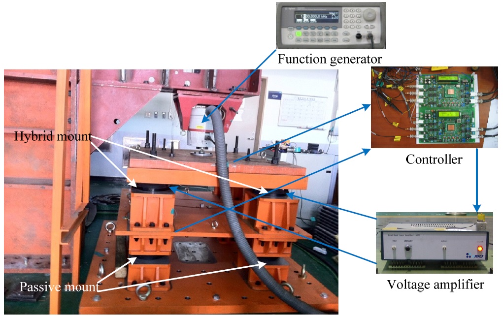
In order to evaluate the proposed hybrid mount system with the filtered-X LMS algorithm, the experimental apparatus was utilized as shown in Fig. 17. Because the voltage input into the piezostack actuator ranges from -350
[Table 3] Design specification of the voltage amplifier for piezostack actuator.
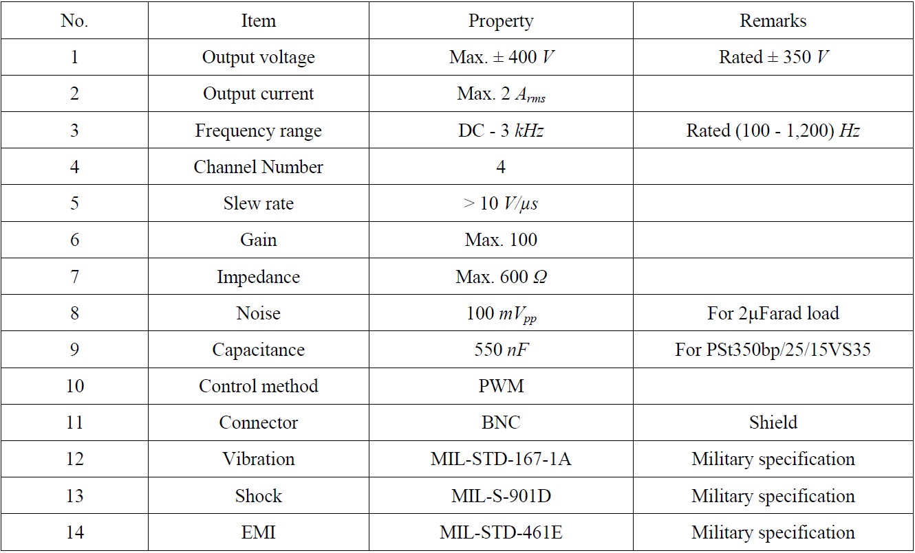
Design specification of the voltage amplifier for piezostack actuator.
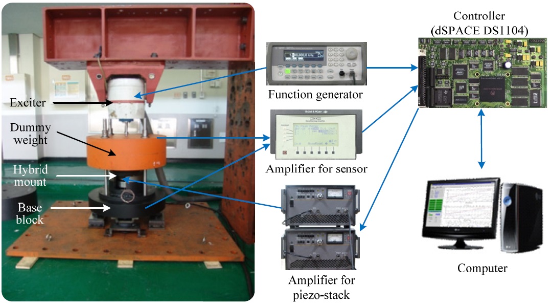
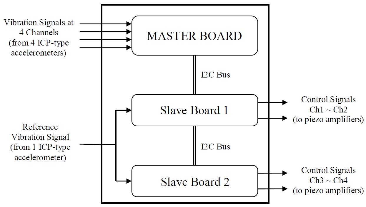
The command voltages to the voltage amplifiers were processed by a specific controller, which consists of a 5-channel analogue-digital (AD) converter, a 4-channel digital-analogue (DA) converter, and a microprocessor for digital signal processing. The AD converter can be connected directly with ICP-type sensors. Fig. 18 shows that the controller works on the basis of 3 dsPIC30F6014 microcontrollers (Microchip, Inc.) as the central processing unit, i.e., one master and two slaves. The voltage calculated in the controller was supplied to the piezostack actuators by the voltage amplifiers, and the measured acceleration signals were also digitalized by the controller. A total of five ICP-type sensitive accelerometers (B&K 752A13) were installed on the dummy weight and the bottom of each of the proposed hybrid mounts. In order to generate periodic external vibration at a specific frequency as unwanted vibration, the exciter (LDS V555), which can adjust the amplitude and frequency via a signal generator, Agilent 33210A, was installed on the top of the dummy weight.
Results
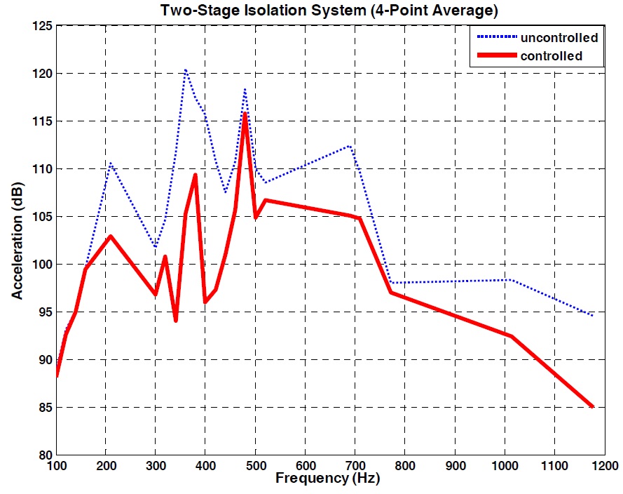
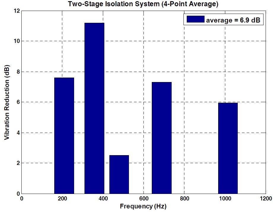
By vertically exciting the dummy weight with the exciter, the active performance test for the proposed hybrid system was carried out. Exciting force was applied to the dummy weight at constant amplitude and constant frequency. The exciting frequency was set up in the range of 100
An inertia-type hybrid mount comprising a rubber mount and a piezostack, with a maximum loading capacity of 500
There are no specific military specifications regarding hybrid mounts for use on naval vessels. Because the hybrid mount was developed based on a resilient mount, both MIL-M-17185A(SHIPS) and MIL-M-17508F(SH) were optionally applied for the performance evaluation of the developed hybrid mount. The proposed hybrid mount was successfully passed on all of the testing items, including shock testing, according to MIL-S-901D. As regards active control performance, the hybrid mount can reduce vibration level by about 13
The hybrid mount system consists of the proposed hybrid mounts, a controller, and a voltage amplifier. The latter was specially designed according to MIL-STD-167-1A (vibration), MIL-S-901D (shock), and MIL-STD-462E (electromagnetic interference). A specific controller, consisting of an AD/DA converter and three microprocessors installed with the filtered-X LMS control algorithm, was also designed instead of a commercial control device. The active control performance test of the hybrid mount system was carried out on the two-stage isolating system. By conducting a series of experimental tests, it was confirmed that the hybrid mount system offers better performance than the passive 6K2000, which is the standard resilient mount of US Navy for use in naval ships.