This study compares the Residual ultimate longitudinal strength ? grounding Damage index (R-D) diagrams produced by two analysis methods: the ALPS/HULL Intelligent Supersize Finite Element Method (ISFEM) and the design formula (modified Paik and Mansour) method ? used to assess the safety of damaged ships. The comparison includes four types of double-hull oil tankers: Panamax, Aframax, Suezmax and VLCC. The R-D diagrams were calculated for a series of 50 grounding scenarios. The diagrams were efficiently sampled using the Latin Hypercube Sampling (LHS) technique and comprehensively analysed based on ship size. Finally, the two methods were compared by statistically analysing the differences between their grounding damage indices and ultimate longitudinal strength predictions. The findings provide a useful example of how to apply the ultimate longitudinal strength analysis method to grounded ships.
A cross sectional area
Aoi original area of the inner bottom
Aoo original area of the outer bottom
Ari reduced (damaged) area of the inner bottom
Aro reduced (damaged) area of the outer bottom
B ship breadth
b double side width
D ship’s depth
h double bottom height
I moment of inertia
L ship length
Mu ultimate hull girder bending moment
Muo ultimate hull girder bending moment at intact condition
R2 coefficient of determination
r1 breadth of the bottom of the rock
r2 breadth of the tip of the rock
α correction factor
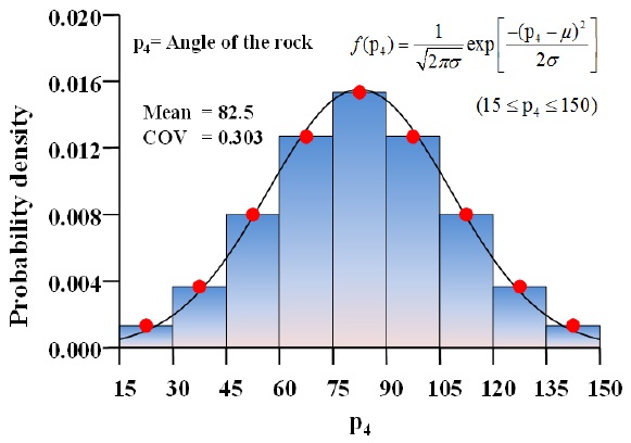
? angle of the rock
Ships are vulnerable to various accidents such as grounding, collision, fire and explosion in addition to age-related degradation such as corrosion, fatigue cracking and localised dents. This study investigates the residual ultimate longitudinal strength of double-hull oil tankers subject to grounding damage. Grounding or collision accidents continue to occur despite concerted efforts to prevent them. A recent example is the Costa Concordia cruise ship, which was grounded on 13 January 2012.
Numerous studies have been performed in relation to grounding or collision accidents, including the assessment of damage to ships (Wang et al., 2002; Paik et al., 2003; Kim, 2013), damage prediction (Simonsen and Friis-Hansen, 2000; Simonsen et al., 2009), structural consequences (Zhang, 2002; Zhang and Suzuki, 2006), hull girder collapse (Pedersen, 1994; Paik et al., 1998; Wang et al., 2000), damage scenarios (Brown, 2002; Samuelides et al., 2008; Paik et al., 2012), modelling (Tabri et al., 2009; Paik, 2007a; Paik, 2007b) and structural designs (Paik, 2003; Samuelides et al., 2009). Research on grounding accidents conducted by Pedersen (2010), Nguyen et al. (2011) and Hong and Amdahl (2012) may also be referred.
Recently, Paik et al. (2012) proposed a new concept, the R-D diagram, for accurately evaluating the safety of damaged ships using the design formula method (Paik et al., 2013) to predict the residual ultimate longitudinal strength of ships damaged by grounding. The method is based on the presumed stress distribution of the mid-ship section (Hughes and Paik, 2010).
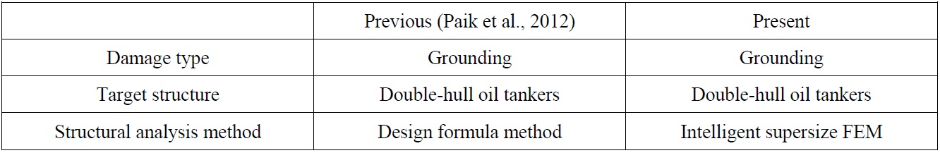
Nevertheless, various alternative analysis methods, such as the idealized structural unit method (ISUM or SMITH method), the non-linear finite element method (NLFEM), the intelligent supersize finite element method (ISFEM) and others can also be used to identify the accuracy and efficiency of structural safety. While Paik et al. (2012) applied the design formula (analytical) method, this study focuses on the differences between the ISFEM (ALPS/HULL) (ALPS/HULL, 2012) and the design formula methods (modified Paik and Mansour method or modified P-M method) (Paik et al., 2013) in assessing the safety of damaged ship structures. The results from the two methods are compared to determine the most practical approach. Table 1 indicates the main differences between previous studies and present study. Based on the calculated results, an R-D diagram is established and the values for the grounding damage index (GDI) and residual ultimate hull girder strength are compared.
[Table 1] The main differences between previous studies and the present study.

The main differences between previous studies and the present study.
PROCEDURE FOR THE DEVELOPMENT OF THE RESIDUAL STRENGTH?DAMAGE INDEX DIAGRAM
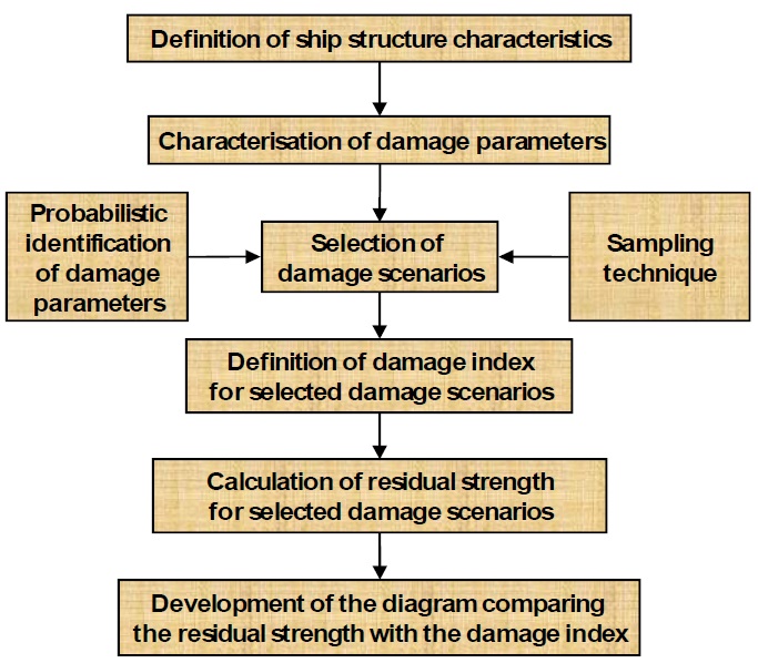
Paik et al. (2012) proposed a new concept for evaluating damaged structures, the R-D (Residual strength ? Damage index) diagram. Fig. 1 shows the general procedure for the development of an R-D diagram. Based on this procedure, R-D diagrams of double-hull oil tankers (Paik et al., 2012) using the design formula (modified P-M) method, bulk carriers (Park et al., 2012), and container ships (Kim et al., 2012a) have been established using the ISFEM (ALPS/HULL) method.
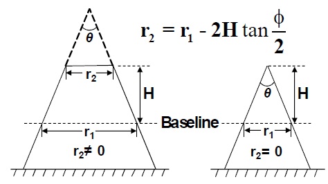
The above procedure can be summarised as follows. After defining the dimensions, geometry and material properties of the target ship structures, the grounding damage parameters should be identified as follows and as shown in Fig. 2 (Paik et al., 2012).
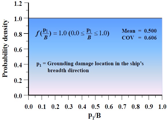
p1 : grounding location in the direction of the ship’s beam.
p2 : height (H) of rock penetrating into the bottom of the hull in the direction of the ship’s depth.
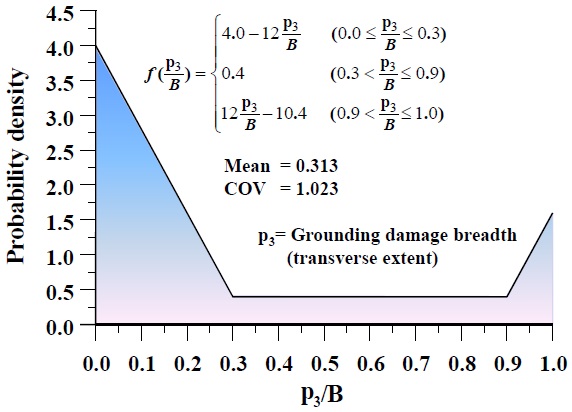
p3 : breadth (r1) of the bottom of the rock at the elevation corresponding to the ship’s baseline and breadth (r2) of the tip of the rock.
p4 : angle of the rock (?).
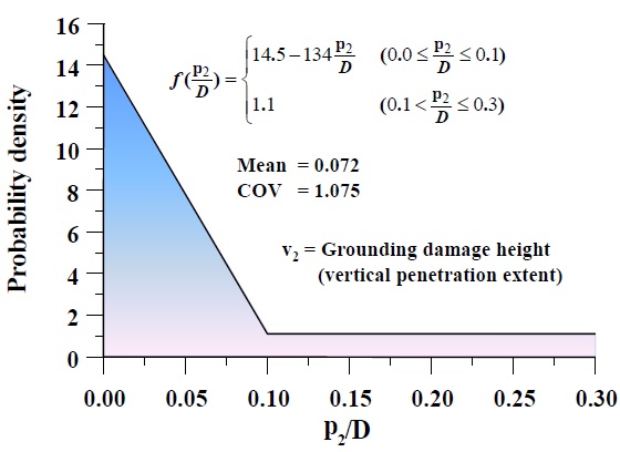
The previous study adopted the probability density distributions provided by the IMO (2003) as reasonable grounding damage scenarios in terms of damage location (p1), damage height (or penetration) (p2) and damage breadth (p3), as shown in Figs. 3(a) to (c). Figs. 3(a) to 3(c) show the IMO’s probability density distributions for the grounding damage parameters and Fig. 3(d) illustrates the distribution of the assumed angles of the rocks. These figures are also employed in this study and the same assumptions used in Paik et al. (2012) are used in this study to select a reasonable number of damage scenarios using the LHS technique (Ye, 1998). This technique takes into consideration economic factors such as computational cost limitations. The expatiation of LHS is omitted, but can be found in Ye (1998). Once the grounding damage parameters (including damage location and extent) have been defined, the residual ultimate longitudinal strength analysis and identification of the grounding damage index (GDI) proceed simultaneously.
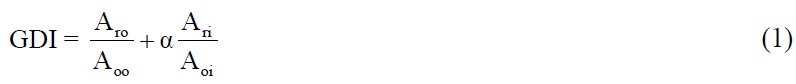
Normally, grounding in double-bottomed structures occurs in both the outer-bottom and the inner-bottom structures. Therefore, the GDI should identify the extent and location of grounding damage for both the inner and outer bottom structures, as shown in Eq. (1). It includes a correction factor (
TARGET STUCTURES AND APPLIED METHODS
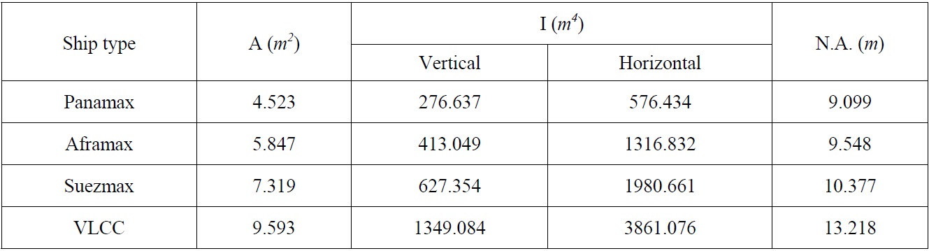
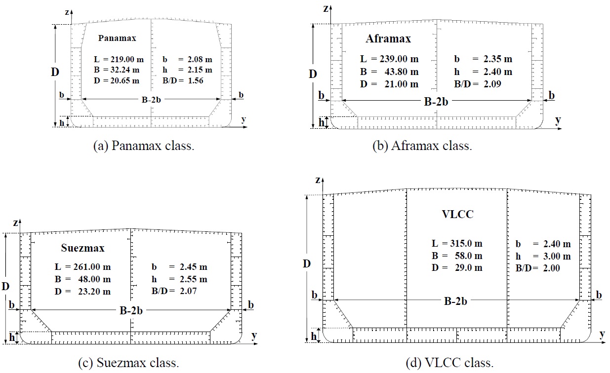
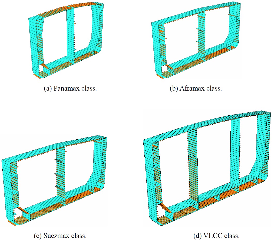
This study examines four types of representative double-hull oil tankers: Panamax, Aframax, Suezmax and VLCC, as shown in Fig. 4 with their principal dimensions. The cross-sectional data are also presented in Table 2.
[Table 2] Cross-sectional data of target structures.

Cross-sectional data of target structures.
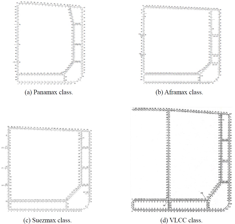
Figs. 5 (design formula method) and Figs. 6 (ISFEM) show the analysis models for double-hull oil tankers. In brief, the design formula (modified P-M) method is based on either the plate-stiffener combination (PSC) model or the plate-stiffener separation (PSS) model.
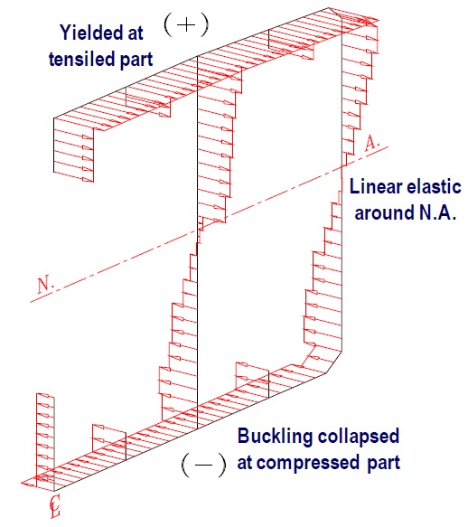
Figs. 5(a) to (d) show the PSC models for four double-hull oil tankers; the figures for the PSS model are omitted here. Design formula provides a 2-dimensional representation but ISFEM adopts a 3-dimensional representation. The important fact to note is that the assumed stress distributions are along the mid-ship section (presumed stress distribution-based method), as shown in Fig. 7. However, this method cannot deal with interactions between local and global failure.
The ISFEM method (ALPS/HULL) is only used for PSS geometric modelling and is based on a numerical formulation with closed form solutions. Therefore, it provides both 2-dimensional and 3-dimensional outputs and can deal with interactions between local and global failure. Hence, ALPS/HULL is suitable for analysing progressive hull collapse. More details on the features of these two methods can be found in Paik and Thayamballi (2003) and Hughes and Paik (2010).
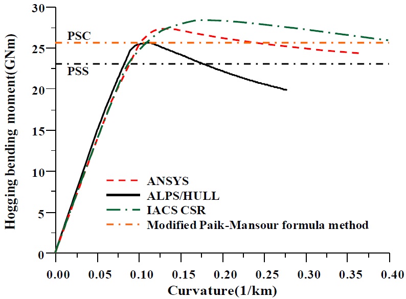
Before analysing the ultimate hull girder strength, benchmark research was performed for various types of vessels by Paik et al. (2013), as shown in Fig. 8. This figure shows the analysis results for a typical double-hull oil tanker. The ISFEM method (ALPS/HULL) was recently applied to various types of ship structures to analyse and identify their structural capacity (Kim et al., 2012b; 2012c; Park et al., 2012).
DEVELOPMENT OF R-D DIAGRAMS AND COMPARISON OF THE TWO METHODS
In this section, R-D diagrams are established using both the ISFEM (ALPS/HULL) and the design formula (modified P-M) method to validate the applicability of both analysis methods. Again, the analysis results are compared in a step-by-step process. The details of both methods can be found in Paik and Thayamballi (2003) and Hughes and Paik (2010). The comparison between the design formula (modified P-M) method (Paik et al., 2013) and ISFEM (ALPS/HULL) (ALPS/HULL, 2012) method begins with the following steps:
1) define the correction factor;
2) determine the GDI; and
3) establish the R-D diagram.
>
Define the correction factor
The correction factor (

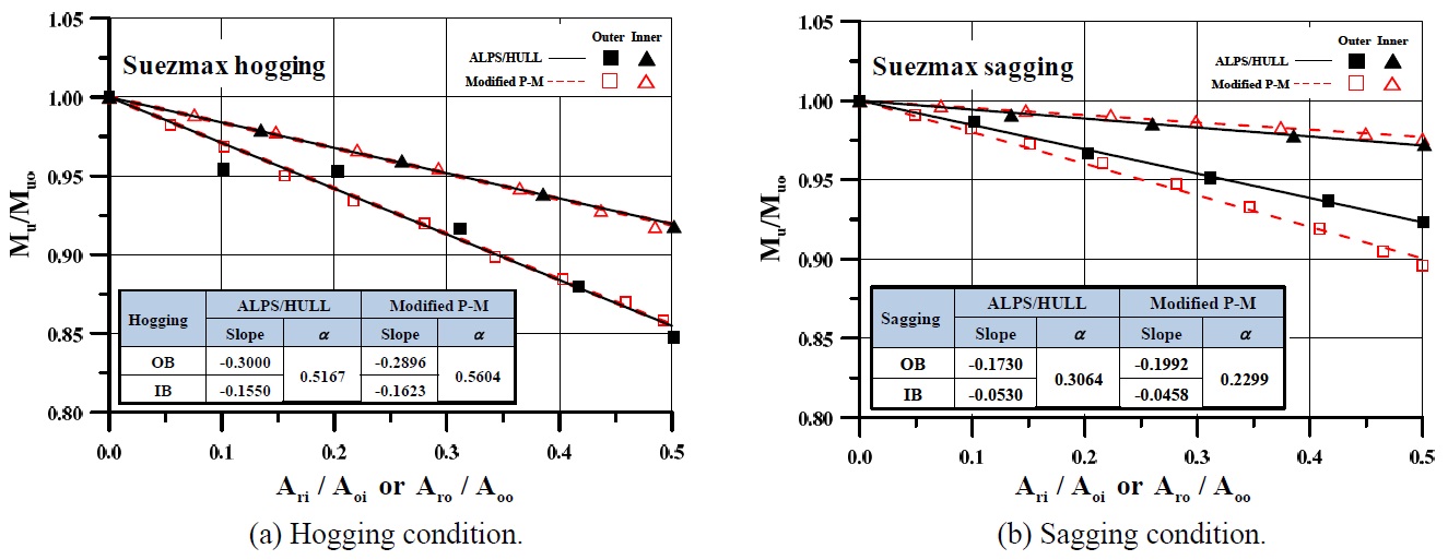
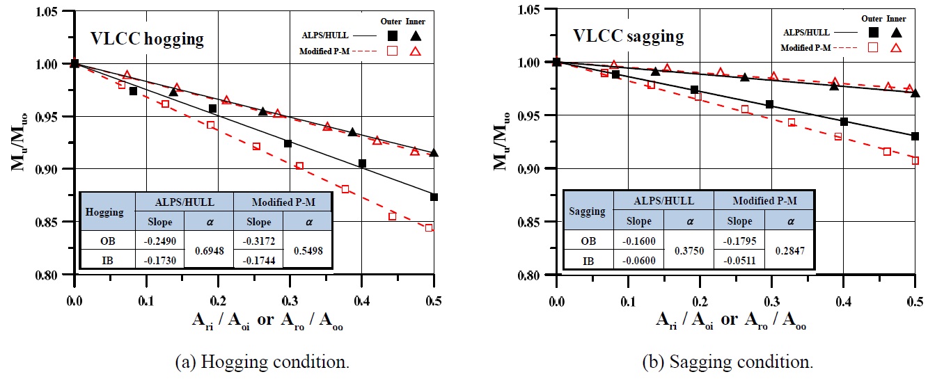
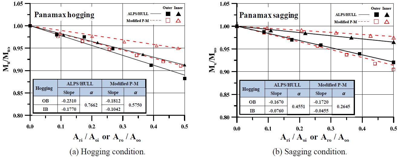
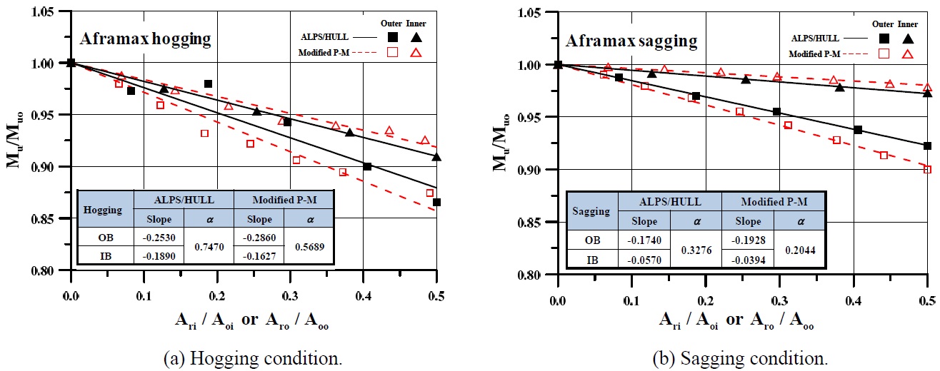
where θIB and θOB are the slopes of the ultimate longitudinal strength versus the curves of the amount of grounding damage for the respective inner and outer bottoms. Figs. 9 to 12 illustrate the comparison results for the calculated correction factors of double-hull oil tankers.
Table 3 shows the correction factors obtained from the results of Figs. 9 to 12. Generally, the trend of the correction factors produced by the ISFEM (ALPS/HULL) method show an upward tendency compared with the design formula (modified P-M) method.
[Table 3] Comparison of correction factors.
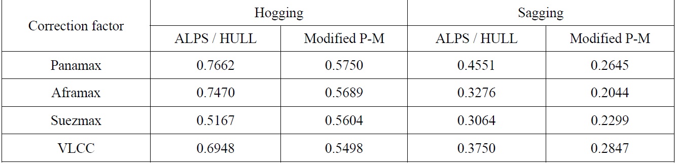
Comparison of correction factors.
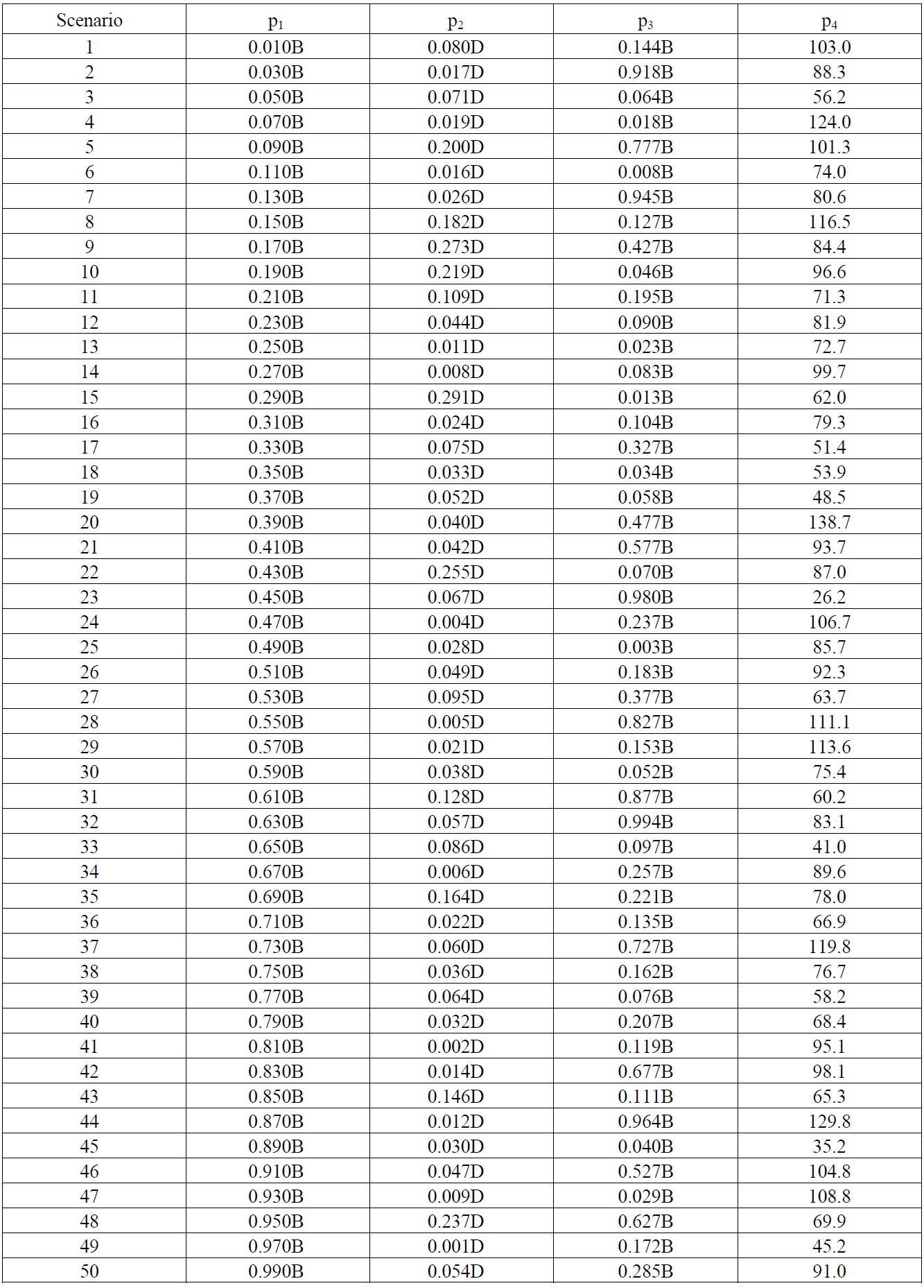
Using the principal dimensions illustrated in Fig. 4, together with the IMO’s probability density distributions and assumptions of the rock’s shape using the LHS technique, four types of grounding damage parameters for 50 grounding damage scenarios are defined and shown in Table 4. The grounding damage indices for 50 grounding damage scenarios are calculated based on the obtained damaged parameters under vertical bending moments based on the values from Eqs. (1) and (2) and Table 3. The results for the calculation of values are covered in the discussion section.
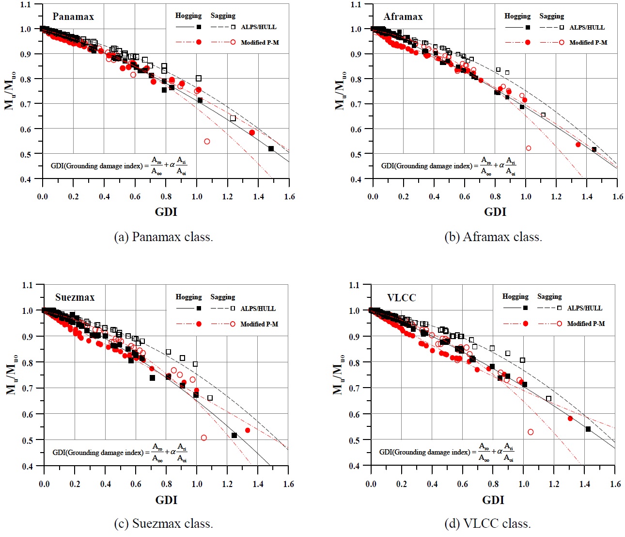
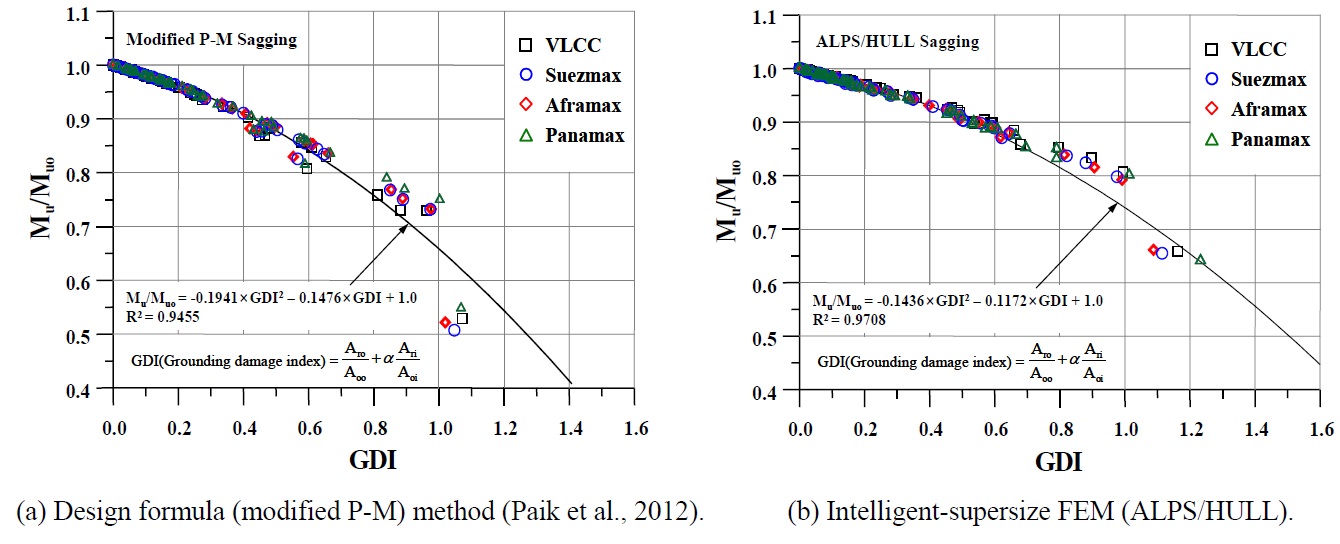
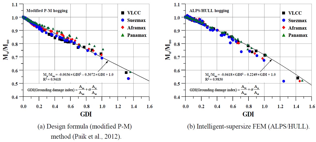
In this section, R-D diagrams are developed based on the calculated residual ultimate longitudinal strength and grounding damage indices. Figs. 13(a) to (d) show the developed R-D diagrams obtained using a curve-fitting method. Figs. 14 and 15 show the R-D diagrams for all double-hull oil tankers using both the ISFEM (ALPS/HULL) and the design formula (modified P-M) method.

The four grounding damage parameters for 50 grounding damage scenarios (Paik et al., 2012).
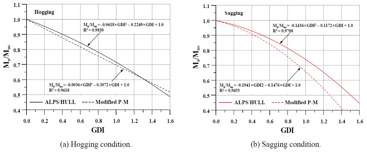
Generally, the R-D diagrams obtained by the design formula (modified P-M) method underestimate the residual ultimate longitudinal strength of double-hull oil tankers in both the hogging and sagging conditions, compared with ISFEM (ALPS/ HULL). The results can be found in Figs. 16(a) and (b).
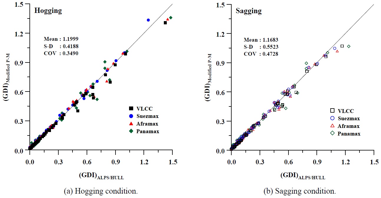
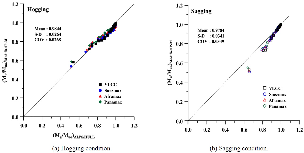
Figs. 17 and 18 show the statistical results based on the obtained outputs. Two parameters, the GDI and the residual ultimate bending moment (Mu), were assessed by considering the vertical hogging and sagging moments. The aim of this study was to compare the residual ultimate bending moment capacity calculated by these two methods. The grounding damage indices were also compared, as shown in Figs. 17(a) and (b). As mentioned in Paik et al. (2013), oil tanker structures can be modelled using the design formula (modified P-M) method using the plate-stiffener separation model (PSS), and those under a hogging moment can be modelled using the plate-stiffener combination (PSC) model.
The ISFEM (ALPS/HULL) method uses the PSS modelling technique. A comparison of the results obtained by these two techniques under the same conditions is shown in Figs. 17(b) and 18(b). PSS modelling is adopted with the design formula (modified P-M) method and ISFEM (ALPS/HULL) in sagging conditions.
In contrast, Figs. 17(a) and 18(a) illustrate the results of the analysis based on PSC modelling (design formula method) and PSS modelling (ISFEM). In this case, the results are somewhat different. The results for the sagging moment conditions are more general using both analysis methods.
Fig. 17(b) indicates that ISFEM produces a better result than the design formula method. However, the results of the design formula method are pessimistic from a designer’s perspective.
Finally, both of these two methods can be applied to analyse grounding damage to double-hull oil tanker structures. The comparison results will be useful for assessing the safety of damaged ships using the abovementioned methods.
Ship grounding accidents frequently occur despite continual efforts to prevent them. To produce salvage plans or to save human lives, safety assessment guidelines that include reliable accident scenarios are needed.
Various methods for estimating the safety of damaged ship structures have been proposed. Among them, analysis methods (e.g., the design formula method) and numerical methods (e.g., intelligent supersize FEM) have been compared to determine the residual ultimate longitudinal strength of grounded ship structures.
This study compared and verified the applicability of the abovementioned methods. To select realistic grounding damage scenarios, the Residual ultimate longitudinal strength - grounding Damage index (R-D) diagram approach was applied to the ISFEM (ALPS/HULL) and design formula (modified P-M) method. The obtained R-D diagrams were compared in terms of their residual ultimate longitudinal strength and grounding damage index (GDI) predictions under vertical bending moments. Future research will also consider collision damage, among other types.