Marine transportation industry is undergoing a number of problems. Some of these problems are associated with conventional marine fuel-oils. Many researchers have showed that fuel-oil is considered as the main component that causes both environmental and economic problems, especially with the continuous rising of fuel cost. This paper investigates the capability of using natural gas and hydrogen as alternative fuel instead of diesel oil for marine gas turbine, the effect of the alternative fuel on gas turbine thermodynamic performance and the employed mathematical model. The results showed that since the natural gas is categorized as hydrocarbon fuel, the thermodynamic performance of the gas turbine cycle using the natural gas was found to be close to the diesel case performance. The gas turbine thermal efficiency was found to be 1% less in the case of hydrogen compared to the original case of diesel.
CO Carbon monoxide
CO2 Carbon dioxide
C12H26 Diesel
CH4 Natural gas
DNV Det Norsk Veritas
EES Engineering Equations Solver
H2 Hydrogen
LH2 Liquefied Hydrogen
ICE Internal Combustion Engine
MDO Marine Diesel Oil
NOx Nitrogen oxides
NG Natural gas
SO2 Sulphur dioxidse
LNG liquefied natural gas
SOx Sulphur Oxides
AFT Turbine air fuel ratio
A / F Air Fuel Ratio
Cex Exhaust heat losses factor
CVair Energy content in the fuel
d Excess air ratio
LCV Lower calorific heat value
mf Fuel mass flow rate
mair Air mass flow rate
mex Exhaust mass flow rate
sfc Specific fuel consumption
R Compression Ratio
T1 air temperature
T3 Combustion temperature
Ta Air Ambient temperature
WCT Work of turbine compressor
WGT Total work generated
WPT Work of the power turbine
WR Work ratio
WT Total work generated
ηcycle Cycle efficiency
ε Peak temperatures ratio
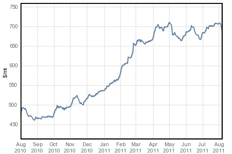
The maritime transportation has been playing a key role in the international supply chain during fast growing international economy. Over 90% of the world trade is carried by the international shipping industry, approximately eight billion tons of international trade goods are transported through the sea each year (Yuquan et al., 2011). The increase of the amount of goods transported by ships has caused an increase in the amount of fuel consumed by shipping transport sector through the last decades with the expectation continues of this trend through the next years. Fossil fuel in its forms diesel and heavy fuel oil consider the mainly marine fuel onboard ships. Last years; the marine fuel has been showed tow basic problems, the first one is the continuous increment in fuel prices. Although the prices have fluctuated up and down, it stills at a high level. All expectations indicate that the prices will continue to increase as shown in Fig. 1 (Bunker world, 2011). Accordingly, that has led to a situation where the fuel cost has become even more significant to the total ship's operating cost. The second problem is ships, emissions, over the past decades, air emissions from ships been the subject of increasing attention throughout the industrial world. Although the actual level of marine air pollution is unclear, the contribution of ships to the global emissions can be roughly indicated as being in the following ranges: nitrogen oxides (NOx), 10?20%; carbon dioxide (CO2), 2?4%; sulphur oxides (SOx), 4?8%. To comply with the previous problems, many studies were carried out to present practical solutions. One of these solutions is using alternative fuel instead of the fossil fuel. The main alternative marine fuel types may be found in two forms: liquid fuels including ethanol, methanol, bio-liquid fuel, and biodiesel; and gaseous fuels, including propane, hydrogen, and natural gas (NG).
Despite the fact that all these fuels are more eco-friendly than Fossil fuel, but some are still difficult to apply extensively on board ships because of low energy content (e.g. methanol and ethanol). The comparison among these types refers that both Hydrogen and Natural gas consider the best alternatives to applying onboard ships specially from the view point of economic and environmental issues (Banawan et al., 2010).
NATURAL GAS AS AN ALTERNATIVE MARINE FUEL
Natural gas is a gaseous fossil fuel that contains methane as its primary component. It is derived from organic matter that was deposited or buried under the earth, millions of years ago (Astbury, 2008)]. From the view point of availability; In the last ten years the world production of natural gas shows annual increase of 3.2%, while the world consumption was 3.05%, refers that the sustainability of natural gas is greater than that of traditional liquid fuel (Diesel oil) (Bp, 2011). The statistics related to Natural gas prices indicate that it has showed a change in the last years. The price has increased in the beginning of 2007, and reached its maximum value in July 2008. However, by the beginning of economic crisis the fuel prices showed a rapid drop and reaching its minimum within a few months. According to the present fuel prices, the price of natural gas
>
Natural gas and the environment
Natural gas is an extremely important source of energy for reducing pollution and maintaining a clean and healthy environment. The main products of the combustion of natural gas are carbon dioxide and water vapor. Table 1 presents a comparison between Coal, Diesel oil and Natural gas from the point view of emissions (EIA, 2009).
[Table 1] Fossil fuel emissions level g/kW.h.
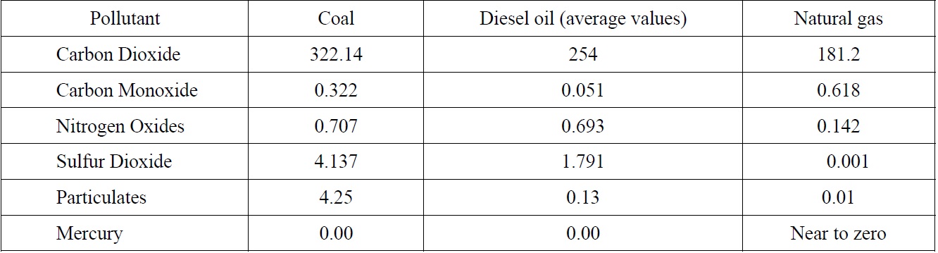
Fossil fuel emissions level g/kW.h.
>
Natural gas forms in marine use
Natural gas can be found in three forms on-board ships: Gas form, Liquid form (liquefied natural gas, LNG); compressed gas form (compressed natural gas). The shipping industry has known LNG decades as a bulk commodity transported by large LNG tankers around the world. Recently a number of forward ?looking companies have been paving the way by pioneering the use of LNG as a fuel especially for ships engaged on regular coastal or short sea shipping services. It is believed that in 5- 10 years time the majority of ship contracted for short sea trades will use LNG as marine fuel oil (Magalog, 2008). Some items may be required to understand the behavior of LNG as fuel onboard ships as follows:
Storage of LNG
LNG is stored as a fuel onboard ships in a cylindrical cryogenic tank which is made from special reinforced plastics with a tensile strength of 1029
LNG fuelled ships bunkering arrangement and piping
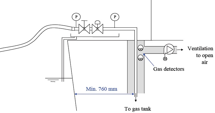
For bunkering arrangement and piping of LNG fuelled ships, in general gas piping is not to pass through accommodation spaces, service spaces or control spaces. Any gas pipe passing through an enclosed space in the ship outside the engine room is to be located within a double pipe or duct, with mechanical under- pressure ventilation giving 30 air changes per hour, and gas detection as shown in Fig. 2. The duct is to be dimensioned to withstand the pressure built up during a pipe rupture. For low pressure piping (max. 10 bar) the duct is to be dimensioned for a design pressure not less than that of the gas pipe (Osberg, 2008).
LNG fuelled system
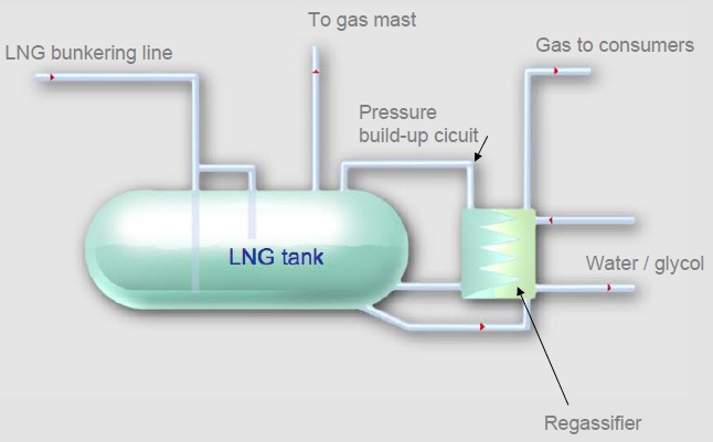
LNG fuel system mainly consists of LNG tank, valves, connections and vaporizer where LNG has to be vaporized to reach a temperature around 15 ℃ before injected into the gas engine. Each tank together with the vaporizer and all valves and tank connections are located within a stainless steel container. This provides a secondary barrier in case of LNG leakage. The container is thermally insulated towards the ship steel to prevent the normal grade ship steel from being cooled down. It is also A60 fire insulated. The container is fitted with ventilation, gas detection and bilge well alarms. Each tank provides gas fuel to two of the engines. The pressure in the gas tank is used to push the gas through the vaporizer and up to the engines. The vaporizers are also used to keep the pressure in the tanks up, by re-injecting vaporized natural gas into the tank as shown in Fig. 3. This is done automatically when the pressure falls below a preset limit. All gas pipes within the vessel are led in ducts that are also provided with ventilation and gas detection.
Safety rules for gas fuelled ships engines installations
Regarding classification societies; it is important to provide relevant rules. The main safety issue when gas is introduced in a ship will be to limit and control the locations where gas may be present, with taken into consideration that an ignition cannot take place unless the natural gas is mixed in a ratio of 5.3 to 14% in air (McGuire and White, 2000). Det Norsk Veritas (DNV, 2007) had the first complete set of rules for “Gas fuelled engine installations” on print already in January 2001, and have had some revisions after that time, the last one in January 2007.
HYDROGEN AS AN ALTERNATIVE MARINE FUEL
Although hydrogen is the universe most abundant element, it is present in the atmosphere only in concentrations of less than one part per million. Most of The Earth's hydrogen is bound up in chemical compounds. Hydrogen for large-scale use should therefore be extracted from a source such as water, coal, natural gas, or plant matter (Welaya et al., 2012). A variety of alternative hydrogen energy production technologies are available in practice, including: Steam reforming, Off-gas cleanup, Electrolysis Photo process, Thermo chemical process and Partial oxidation of hydrocarbons (Dincer, 2008; Welaya et al., 2011).
>
Environmental aspects of hydrogen energy
Scientists anticipate that the greatest potential for clean air from the exhaust of power plants may be obtained by using the hydrogen as fuel especially in Internal Combustion Engines (ICE). When hydrogen is burned in a combustion chamber with air, the result is water vapor plus traces of nitric oxides derived from the nitrogen content in the air. While the hydrogen consumed by either combustion or a fuel cell produces only water as a product. The high temperatures involved in combustion may stimulate some NOx production from nitrogen and oxygen in the air, but this problem is common to other fuels and can be controlled. Unlike other fuels, hydrogen contains no other pollutant producing elements, so it has no potential to produce Sulphur dioxide (SO2), Carbon monoxide, (CO), CO2, volatile organic chemicals, etc (Robert, 1996; Dincer, 2008).
One of the main advantages of using hydrogen in marine application is the higher heating value for the same fuel quantity compared to any other fuel. Many researches had been carried out to demonstrate the possibility of using hydrogen for marine power plants. Morsy El Gohary (2008) suggested that they are need to some modification in case of using hydrogen in (ICEs) from the view point of engine design. Welaya et al. (2011) introduce a good solution to replace or working with conventional marine power plants by using fuel cell power plant operated with hydrogen produced through water or electrolysis or hydrogen produced from N.G, gasoline or diesel fuel.
Hydrogen onboard storage
The storage of hydrogen onboard ships must be in the liquid form since it provides the largest amount of hydrogen stored in minimum volume. The LH2 tanks are constructed from aluminum alloy and insulated by a dual 75
Hydrogen safety
Hydrogen is no more or less dangerous than other flammable fuels, including gasoline and natural gas. In fact, some of hydrogen’s differences actually provide safety benefits compared to gasoline or other fuels. An explosion cannot occur in a tank or any contained location that contains only hydrogen. An oxidizer, such as oxygen must be present in a concentration of at least 10% pure oxygen or 41% air. Hydrogen can be explosive at concentrations of 18.3-59% and although the range is wide, it is important to remember that gasoline can present a more dangerous potential than hydrogen since the potential for explosion occurs with gasoline at much lower concentrations of 13.3%.
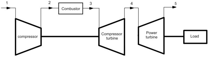
EFFECT OF USING ALTERNATIVE MARINE FUELS ON GAS TURBINE PERFORMANCE
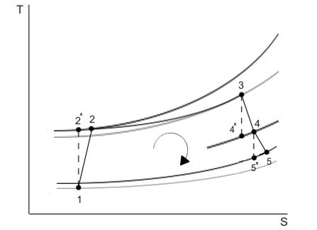
One of the marine power plants that very sensitive by fuel type is gas turbines that due to the difference of combustion process from the other plant. To illustrate the possibility of using marine alternative fuels (Natural gas & Hydrogen ) as a main fuel for gas turbine power plant instead of diesel oil ; a model of LM2500 gas turbine of General Electric. Fig. 4(a) will used as a case study, while Fig. 4(b) illustrates the (T-S) diagram for gas turbine system.
The ideal cycle does not provide a good representation for the real case since some of the assumptions made are somehow far from reality. Table 2 shows a comparison between ideal and real Brayton cycles as (Cohen et al., 1996).
[Table 2] Ideal and real Brayton cycles comparison.
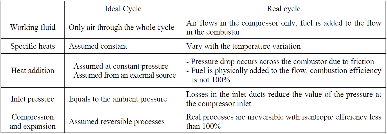
Ideal and real Brayton cycles comparison.
For the purpose of studying the gas turbine engine performance, the working cycle of that engine has to be defined first. Gas turbines work with the Brayton cycle where four consecutive processes take place; isentropic compression in the compressor, constant pressure heat addition in the combustor, isentropic expansion in the turbine and constant pressure heat rejection.
Fig. 4(b) shows the cycle in case of a free power turbine installed after the compressor turbine. Point 4 is now moved up to the pressure line between the two turbines and point 5 is now the exhaust point after the engine. Table 3 presents the main characteristics of the mode, while Table 4 shows the principle properties of the various fuel types.
[Table 3] LM2500 main data (Anon, 2011).
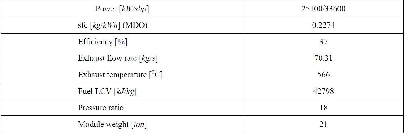
LM2500 main data (Anon, 2011).
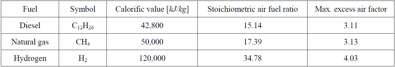
Fuels properties.
The gas turbine thermodynamic equations are computerized using Engineering Equations Solver (EES) program, where the thermodynamic properties of the substances under study can be easily obtained using the built-in functions and data. EES used for performing a modeling for LM2500 gas turbine. The modeling has been done assuming constant power output in both cases of natural gas and hydrogen. In other words, the performance of the engines is assessed on the basis of same power achieved. The program was used to show effect of the fuel properties on gas turbine performance assuming the initial conditions of inlet temperature and pressure are 15 C and 1 bar respectively as following:
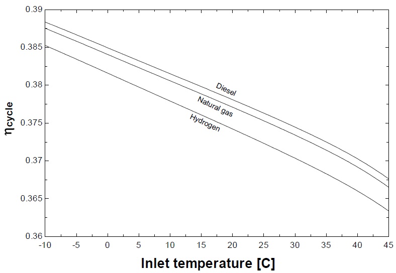
The cycle efficiency (

It has been found from the study that both gaseous fuels give lower efficiency than the original case of diesel for the same power output as shown in Fig. 5. This will be cleared later while discussing the air flow rates for the three cases.
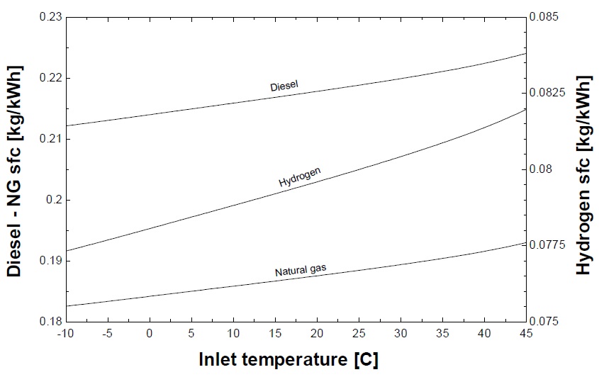
The specific fuel consumption is determined by dividing the mass flow rate by the output power.

The higher calorific value for both natural gas and hydrogen if compared to diesel reduces the quantity of fuel used to give the same heat output. Therefore it is observed from Fig. 6 that the specific fuel consumption for natural gas and hydrogen is lower than that of diesel. This could be an advantage from the point of view of storage onboard the ships, but the fact is different due to the lower density of these two fuels compared to the diesel.
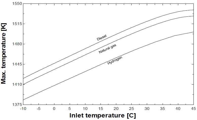
The peak temperatures ratio (

It was taken into consideration during the study to control the different parameters of the thermodynamic model in both cases of hydrogen and natural gas to avoid obtaining higher combustion temperatures than the case of diesel, and this was to keep away from the need to increase the turbine blades cooling. Therefore, the obtained peak temperatures are for the natural gas and hydrogen are lower than that obtained in the case of diesel as illustrated in Fig. 7.
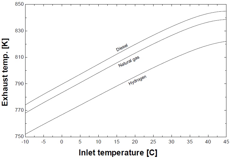
Due to the lower maximum temperatures achieved in the case of both gaseous fuels, the exhaust temperatures follow the same trend with lower temperatures obtained for hydrogen and natural gas as shown in Fig. 8.

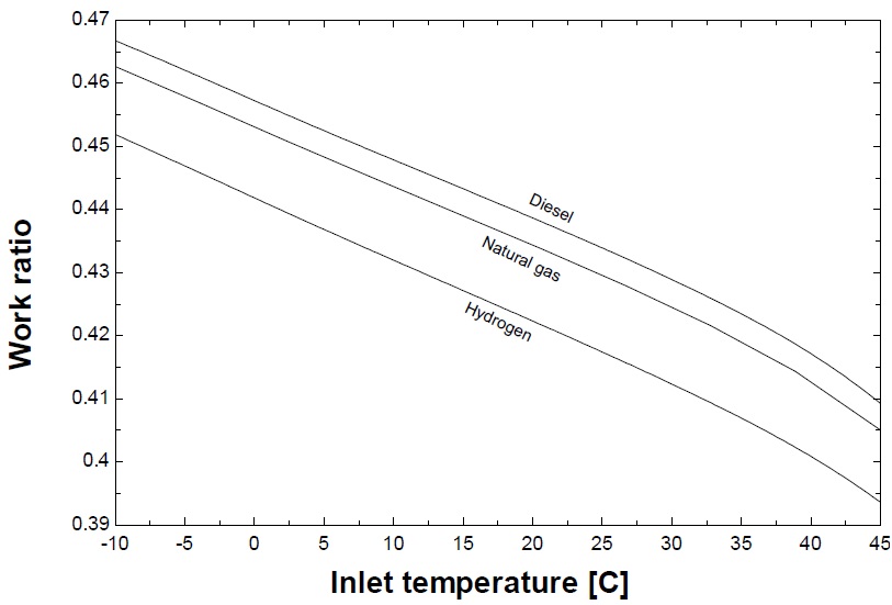
The work ratio, which is the ratio between the work of the power turbine and the total work generated from both turbines, is determined as follows,
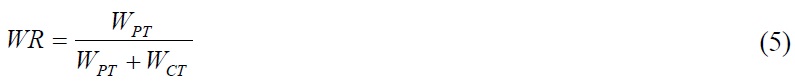
The work ratio is that ratio between the useful work developed inside the engine to the total work developed Fig. 9 shows this ratio. Due to the lower efficiency for gaseous fuels, the work ratio also appeared to be inferior to that in the case of diesel.
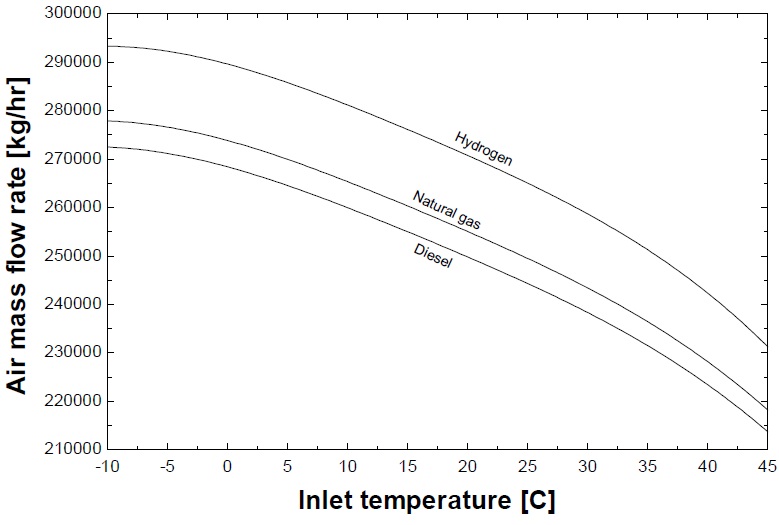
The flow inside the turbines is composed of both air and fuel, but since the study is made using the air as the only working fluid, the flow rate inside the turbine is regarded to be composed of two air flows; the air from the compressor plus a quantity equals to the amount of injected fuel. Effect of fuel type on this amount can be notified as shown in Fig. 10.

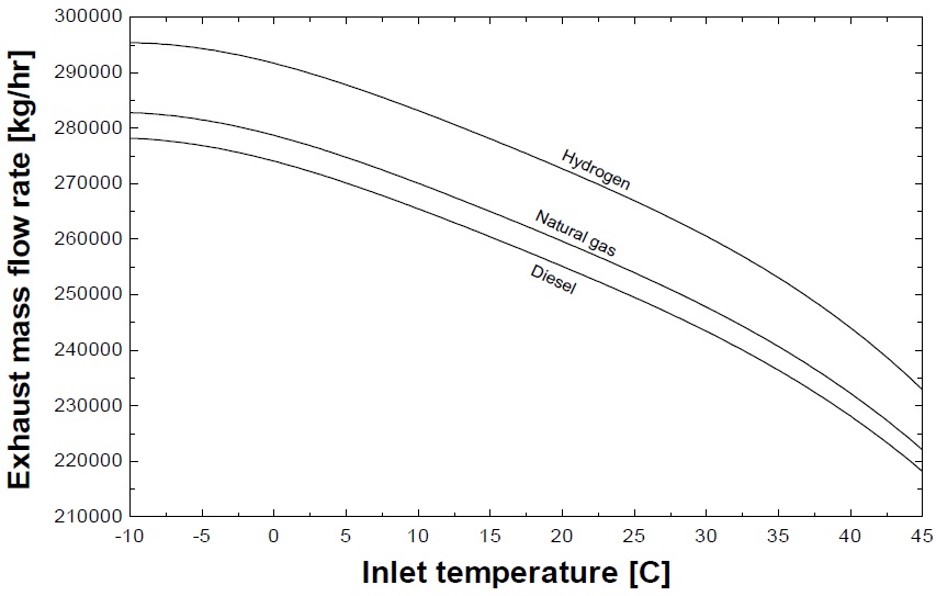
The exhaust mass flow rate is the sum of both flow rates of the air and the fuel.

Fig. 11 shows that following the increase in air mass flow rates for natural gas and hydrogen, the exhaust also is increased but by a smaller percentage if compared with the diesel case, this smaller increase is due to the lower fuel flow rates for both gaseous fuels. This change in mass flow rates through the compressor and turbines leads to a deviation in the compressor turbine matching, so gaseous fuels cannot replace the ordinary fuels without large changes in performance. Table 5 summarized the comparison among the three fuel types from the point view of thermodynamic performance.
[Table 5] Main study results for the three fuels at 15℃ ambient temperature.
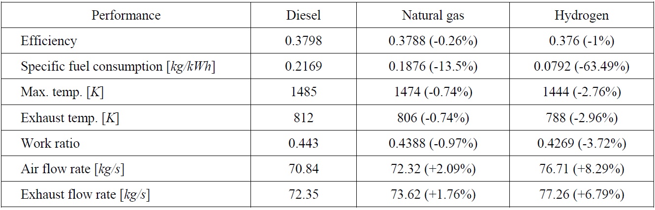
Main study results for the three fuels at 15℃ ambient temperature.
The first conclusion that must be stated first is that the natural gas and hydrogen can be successfully used as alternatives to replace the currently used diesel fuels in the marine gas turbines. For the short term development the natural gas provides ideal solution for the marine applications. Also, the thermodynamic performance using the natural gas in the gas turbine cycle was found to be close to the performance when diesel oil is used. With about 0.25% efficiency reduction at the ISO design conditions, the natural gas provides an excellent replacement for diesel.
For the hydrogen, it was found that many modifications required to be made to reach the optimum performance. The gas turbine thermal efficiency was found to be 1% less in the case of hydrogen when compared with original case of diesel. The hydrogen application in gas turbines cannot be considered as a near future solution unless the inherent problems of hydrogen are solved by using the proper techniques that are technically and economically feasible. It should be noted that, the natural gas can be used in the marine field confidently to improve the maritime environment and keep the marine power plants performance in its good levels.