The Critical Heat Flux (CHF) of water with dispersed alumina nanoparticles was measured for the geometry and flow conditions relevant to the In-Vessel Retention (IVR) situation which can occur during core melting sequences in certain advanced Light Water Reactors (LWRs). CHF measurements were conducted in a flow boiling loop featuring a test section designed to be thermal-hydraulically similar to the vessel/insulation gap in the Westinghouse AP1000 plant. The effects of orientation angle, pressure, mass flux, fluid type, boiling time, surface material, and surface state were investigated. Results for water-based nanofluids with alumina nanoparticles (0.001% by volume) on stainless steel surface indicate an average 70% CHF enhancement with a range of 17% to 108% depending on the specific flow conditions expected for IVR. Experiments also indicate that only about thirty minutes of boiling time (which drives nanoparticle deposition) are needed to obtain substantial CHF enhancement with nanofluids.
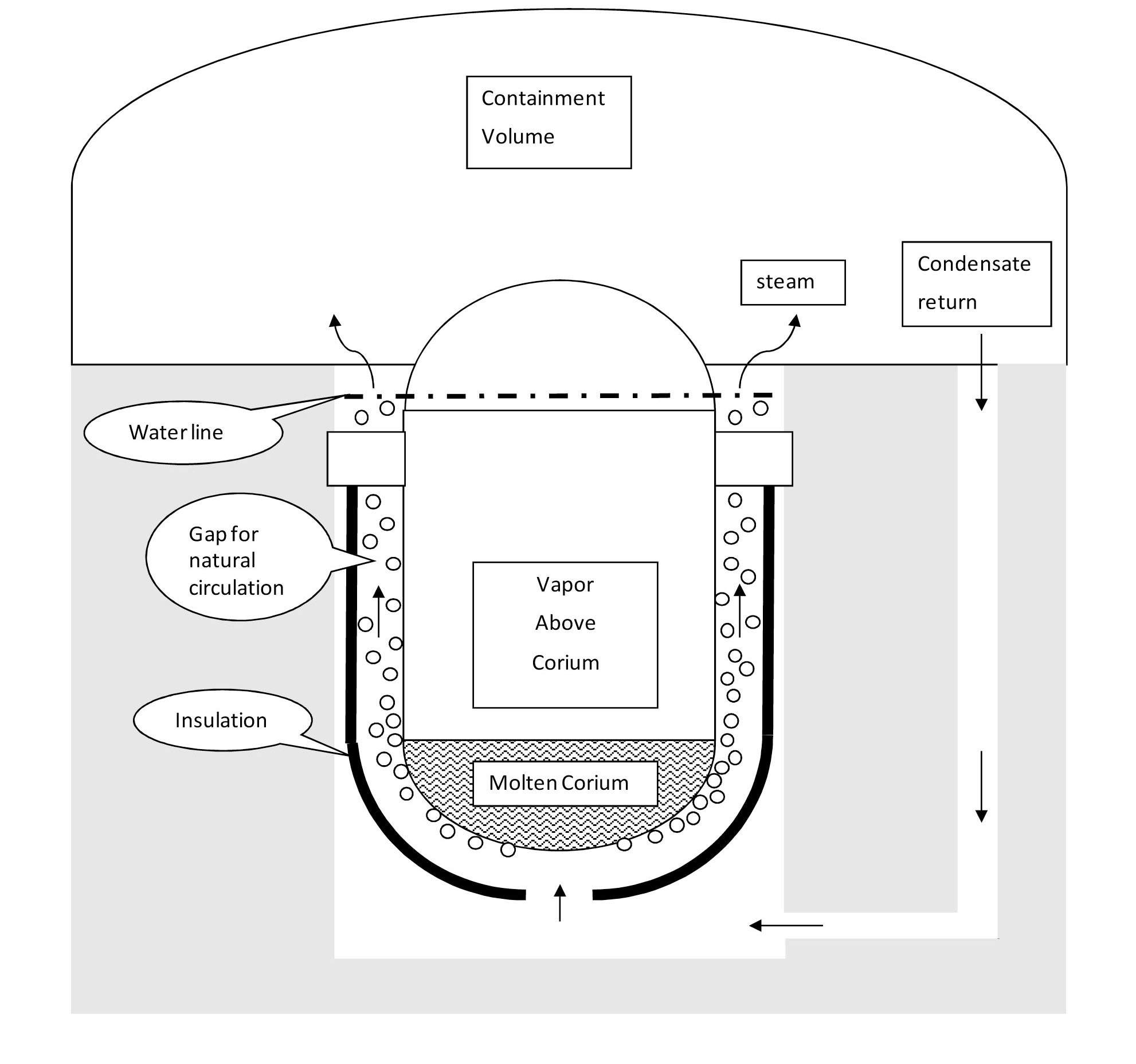
In-Vessel Retention (IVR) is a severe accident management strategy in which vessel breach by the molten corium is prevented through effective decay heat removal on the outer surface of the vessel. IVR eliminates molten core concrete interaction and ex-vessel fuel coolant interaction, thus mitigating the challenges to the containment, and ultimately reduces the source term for fission products release from the containment [1]. IVR entails flooding the reactor vessel cavity, once it is recognized that core damage and fuel melting are likely. In the Westinghouse’s AP1000 design [2], the vessel cavity is flooded with water from the In-Reactor Water Storage Tank (IRWST), which removes the decay heat as it boils and flows by natural circulation in the gap between the vessel outer surface and the vessel insulation (see Fig. 1). The vapor generated mixes into the containment atmosphere, is condensed by the passive cooling of the containment steel shell, and then flows back down into the vessel cavity. The pressure is near or above atmospheric (1 to 3 bar), depending on the initiating event, e.g. large-break Loss Of Coolant Accident (LOCA). IVR is thermally limited by the occurrence of CHF on the vessel outer surface, as CHF would result in localized creep failure of the vessel [3], which is made of carbon steel whose yield strength drops significantly at temperatures above 625 ℃. Because of the proportionality between decay power and nominal core power, CHF in
the IVR situation can constrain the nominal power of some new plants like AP1000. The IVR strategy has also been adopted by other PWR designs including: VVER-440, and the South Korean APR1400 [1][4].
Dispersing nanoparticles in water is an effective way to enhance its CHF. Therefore, the main objective of the work described herein was to determine whether the use of alumina nanoparticles can increase CHF, relative to water, at the specific flow conditions relevant to IVR, i.e. downward-facing boiling in horizontal to vertical upflow [5]. If so, the margin for the IVR strategy could be increased [6], thus opening the possibility of using the IVR approach in higher-power density reactor designs, such as the expected uprated version of the AP1000 for the Chinese market labeled the CAP1400 (~1400MWe) [7]. A study of nanofluids application to IVR, including the conceptual design of nanofluid delivery systems to the cavity was presented Hannink, et al. [6].
The main CHF experimental work in support of IVR was done at the University of California, Santa Barbara (UCSB) [8], the Sultan facility in France [9], the University of California, Los Angeles (UCLA) [10], the CYBL facility at Sandia [11], and Penn State University (PSU) [12]. The PSU downward facing, pool boiling CHF experiments have also been done with water and pre-coated surfaces and have shown a strong dependence on angle. Studies have covered both general conditions of downward facing surfaces and specific reactor design geometries [13][14] [15][16][17][18][19][20][21][22][23][24][25][26][27][28] [29][30].
USCB and Sultan experiments involved large-scale, two-phase flow loops. CYBL and PSU each involved smallscale vessel geometries and pool boiling. The UCSB experiment was a full-scale vertical slice of the vessel/insulation gap that was used for the AP600 (Configuration III) and AP1000 (Configuration V) design certification, with buoyancy-driven natural circulation along semicircular shaped cartridge heaters made of copper. The Sultan facility was a pump-driven system with a 4-m flat plate heater that could be configured at various angles. UCSB conditions were atmospheric at the highest point. Sultan experiments had a range of pressures, qualities, angles, and mass fluxes. From the in-vessel corium work and UCSB experiments a power profile supporting the safety analysis for the Westinghouse designs has been accepted by the NRC [31]. The power profile captures the decay heat source, expected oxide crust development, and light metal stratification.
The working fluid used in all the aforementioned studies was always water. None used nanofluids.
Nanofluids are colloidal dispersions of nanoscale (10-9m) engineered particles. The base fluids can be water, refrigerants, oils or any other. The particles are generally sized in the 1 to 100 nm range. Alumina [Al2O3] nanoparticles used herein had an average diameter of ~40 nm, as measured with dynamic light scattering. The base fluid used throughout the experimental matrix of this work was De-Ionized (DI) water. The literature on nanofluids is now too large to be summarized here. Our remarks are limited to previous work done at MIT over the past 7 years, leading up to the current study. The interested reader can find many additional papers cited in this section. CHF and quenching heat transfer of nanofluids have been investigated in various geometries (upward facing flat plates, spheres, rodlets, tubes, wires), test conditions (atmospheric and above-atmopsheric pressure, saturated pool boiling, and highly subcooled flow boiling), nanofluid types (alumina, zinc oxide, silica, diamond), and surface materials (stainless steel and zircaloy, nickel-chromium alloys) [32][33][34]. CHF enhancement, Leidenfrost temperature enhancement and quench rate acceleration have been observed for nanofluids with respect to DI water, under the vast majority of conditions tested [35]. In particular CHF enhancement (sometimes as high as 200%) seems to correlate with boiling-driven deposition of nanoparticles on the heater surface, which alters its wettability, porosity and roughness, thus having a strong effect on boiling heat transfer.
Alumina has shown one of the largest CHF enhancements of the nanoparticle materials tested to date at MIT [36][37]. Alumina nanofluids have also exhibited colloidal stability in chemistries and radiation fields relevant to IVR [38]. For these reasons alumina nanofluids were chosen in the present study. The experimental investigation completed herein specifically addresses geometric and flow conditions expected in IVR for the AP1000. A direct comparison is made between the CHF of water and that of alumina nanofluids with identical flow conditions and geometry, to quantify the CHF enhancement.
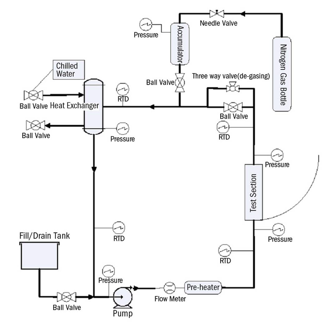
The two-phase flow loop shown in Fig. 2 was used to measure CHF in this study. The primary loop components include: centrifugal pump, pre-heater, test section, accumulator, and condenser. Joule heating to the test section is driven by two 18 kW DC power supplies operated in parallel. The 2 hp pump allowed for fluid temperatures up to 180 ℃ with low net positive suction head. The 2 kW pre-heater allowed for control of the test section inlet temperature. The accumulator with viton bladder provided volume expansion of the working fluid and system pressure control, via a nitrogen gas system. The tube side of the shell and tube condenser was plumbed into the MIT chilled water system and provided condensation on the shell side. All loop wetted metallic components are stainless steel.
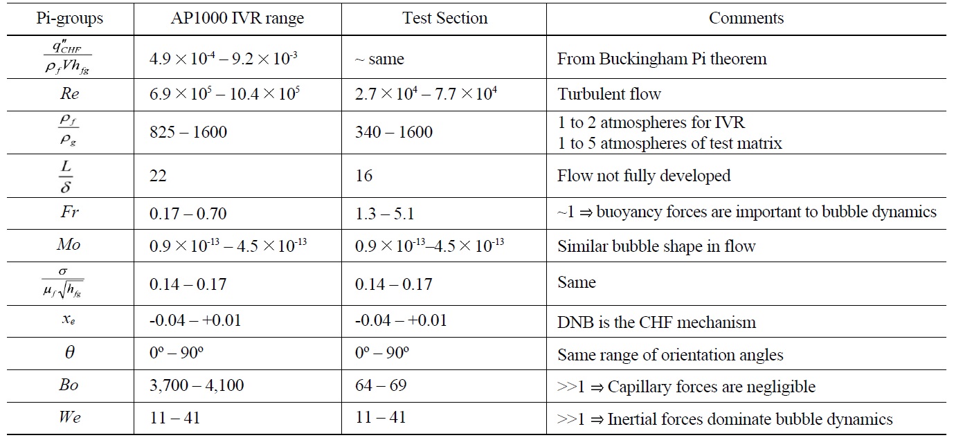
The test section was designed to have single sided heating and swing through all angles from horizontal (0°) to vertical (90°). The test section was also designed to be hydro-dynamically similar to the vessel/insulation gap in AP1000 through scaling analysis [39]. The results of the scaling analysis are reported in Table 1.
The test section body material is stainless steel 316.
[Table 1.] Pi-groups for CHF in IVR for AP1000 and the MIT Test Section

Pi-groups for CHF in IVR for AP1000 and the MIT Test Section
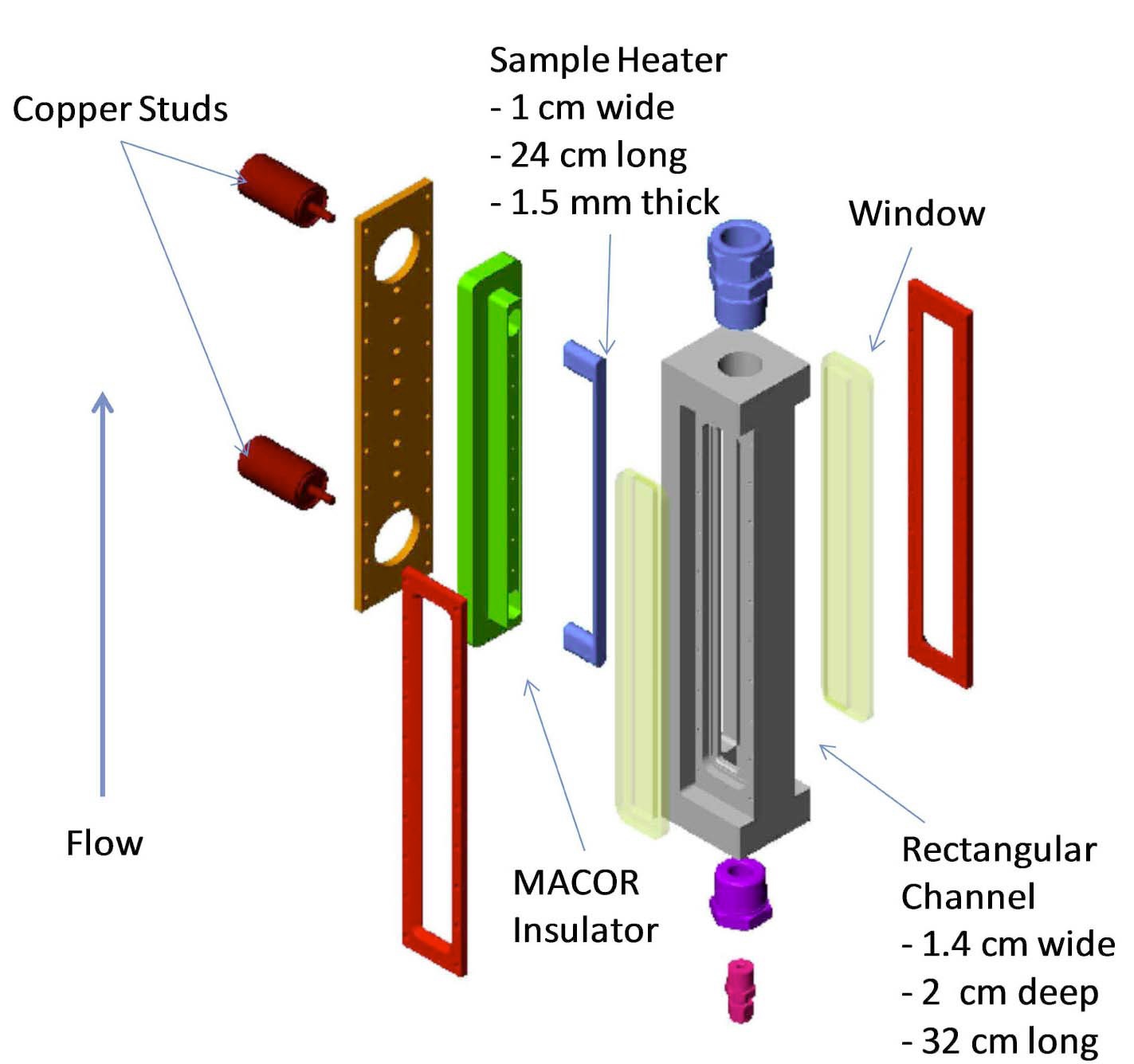
The rectangular flow channel is 1.43 cm (0.563”) wide, 2 cm (0.787”) deep, and 31.75 cm (12.5”) long (see Fig. 3). The test heater sample is a flat plate with studs at each end to provide for coupling to DC electrodes. The heater then sits within a MACOR insulator that directs the heat flux to the surface exposed to the fluid flow. The heater flow-facing dimensions are 1 cm width, 24 cm long, and 1.5 mm thickness. The heated length between the studs is 20 cm. Electrical DC current flows into the test sample through the two (2) copper studs with threaded leads. Orings on each copper stud provide a water tight seal.
The loop was fitted with six (6) types of measurements: temperature, pressure, flow rate, voltage drop, current, and dissolved oxygen. A total of twenty-six (26) digital measurements were made at each scan using an Agilent DAS and LabVIEW virtual instrument program. The scan rate was generally set at three (3) seconds. Calibrations were completed for all measurement devices: initial calibrations and follow-up calibrations. LabVIEW programming also allowed for on-the-fly calculations, data capture, graphical display, and remote control of the pump and power supplies. The current and voltage drop measurements were utilized to calculate joule power, which is compared to thermal flow power. Propagation of temperature, flow, and geometry measurement uncertainty resulted in a 4.0% CHF uncertainty (σCHF =4.0%) [5]. Heat balance at subcooled conditions indicated that Joule power and thermal flow power (=
The test procedure for downward CHF experimentation had four main steps:
1) Fluid preparation. This involved appropriate blending of DI water and high concentration alumina nanofluid (20% by weight supplied by Nyacol Technologies), to realize two concentrations: 0.001% and 0.01% by volume. These low concentration nanofluids exhibited good colloidal stability, with no indication of sedimentation over a period of many months. At these low concentrations, the thermo-physical properties of the working fluid are not meaningfully different from DI water (i.e., density, specific heat, etc.) [40].
2) Heater sample preparation. This involved sandblasting the surface with silica beads, cleaning with acetone, and then de-ionized water (DI).
3) Initial instrument readings, loop set-up and degassing. Once the instrumentation was checked, the loop was vacuum evacuated, and then the fluid drawn into the system. The vacuum helped reduce the amount of non-condensable gases remaining in the loop post filling. Then a degassing procedure of heating the fluid to 60℃ and periodic system gas purging was completed. Dissolved Oxygen (DO) was measured after degassing, as an indicator of the presences of non-condensable gases in the fluid. The objective was to have a consistent fluid with similar dissolved non-condensable gas levels for all tests. Degassing was deemed satisfactory when DO was ~ 4 ppm.
4) Stepped Heat-up to CHF. Power to the test section was increased in small steps with a few minutes in between each step to allow for steady-state to be reached, until CHF was finally detected. CHF always resulted in destruction of the test heater, which had to be replaced for the next test.
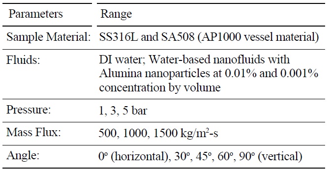
A series of eighty-five (85) CHF experiments were run, with the conditions summarized in Table 2. DI water and alumina nanofluids were compared for identical pressure, flow rate, inclination angle, exit quality and heater material. This approach allowed for isolation of the relative effect of the nanoparticles on CHF. The test section exit conditions were always saturated with nearzero quality, χe. Two (2) surface materials were used: stainless steel 316L and SA-508. SA-508 is the reactor pressure vessel material used for the AP1000. Five (5) tests were done with SA-508. Four (4) SS316L tests had a pre-oxidized surface achieved by baking the heater at 800 ℃ for one hour. Otherwise, each heater had the standard cleaning and sandblast preparation described in the previous section. Forty (40) CHF runs were completed with alumina nanofluids. Of these nanofluid tests thirty-eight (38) had a concentration of 0.001% and two (2) a concentration of 0.01% by volume. Three (3) target mass fluxes were tested: 500, 1000 and 1500 kg/m2-s. The associated entrance velocities were 0.5, 1.0 and 1.5 m/s, respectively. A few additional experiments were also run to quantify the effect of boiling time on nanofluid CHF. These mass fluxes bound natural circulation flow rates expected for the AP1000 [8] and scaling analysis summarized in Table 1. Generally, all tested conditions were run twice. If the resulting CHF measured was different by more than 10%, a third case was completed to reduce the data spread.
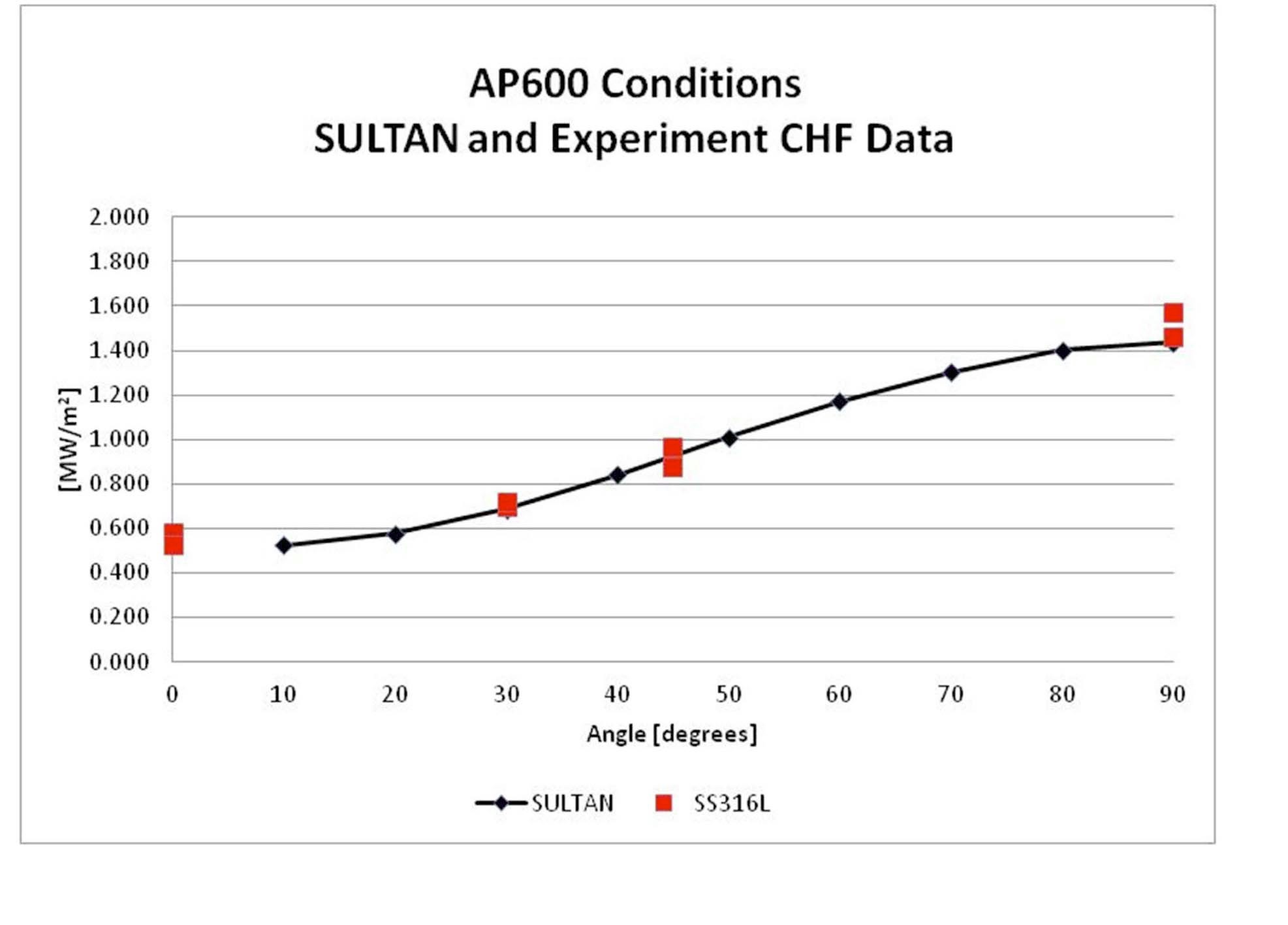
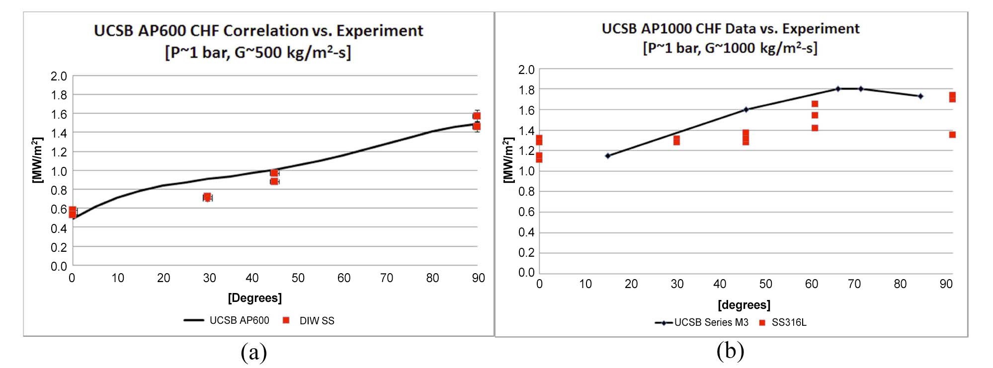
Validation of the experimental facility was accomplished by comparing the water-only data to data for similar conditions obtained at UCSB [8] and the Sultan facility [9].
[Table 2.] List of Parameters Varied in Experimental Matrix

List of Parameters Varied in Experimental Matrix
The results are shown in Figures 4 and 5. Agreement is good for correlations developed by UCSB and Sultan for mass flux conditions similar to the AP600 and UCSB data points reported for mass fluxes associated with the AP1000.
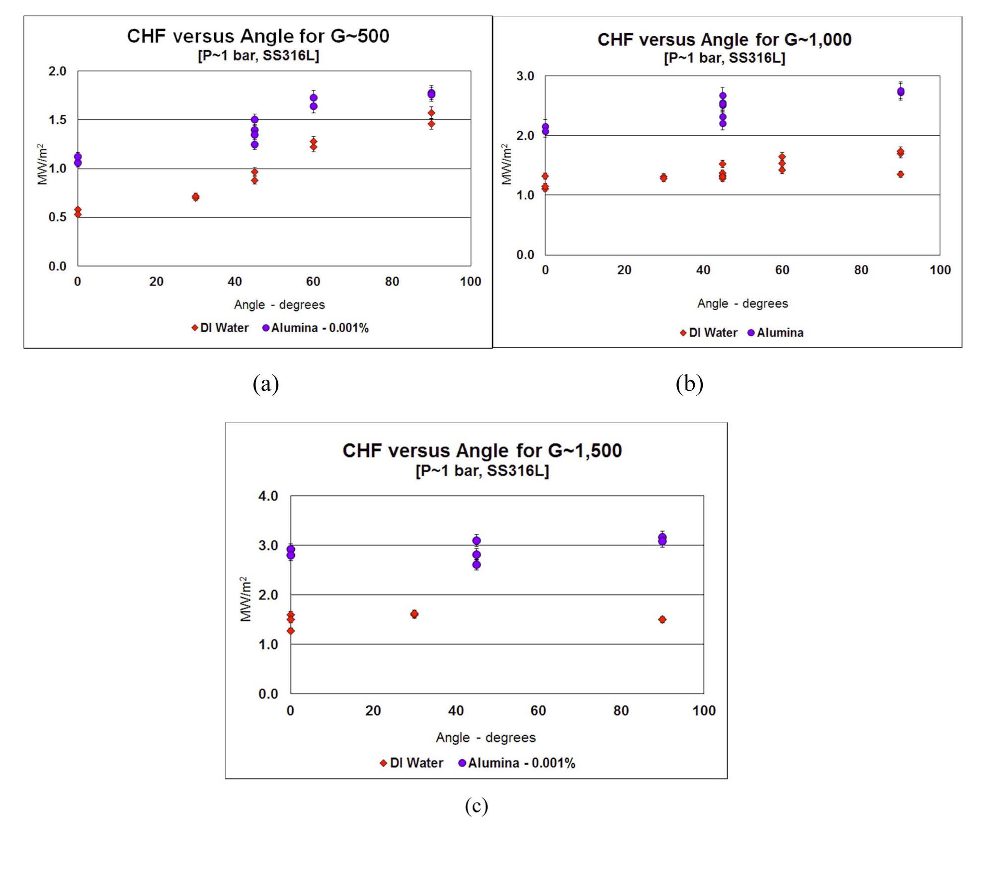
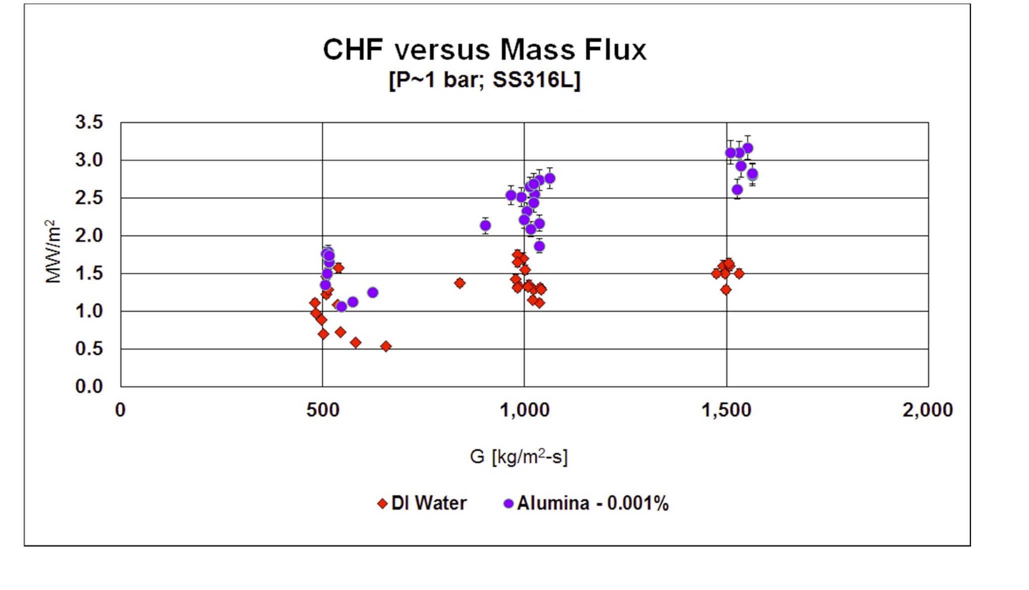
All nanofluids and DI water data for the SS316L heaters at atmospheric condition are plotted in Figure 6. CHF increases with mass flux for both water and alumina. This trend suggests that CHF occurs via a Departure from Nucleate Boiling (vs. dry-out) mechanism. Two-phase flow regime maps suggest the flow conditions in the vast majority of our dataset were bubbly on intermittent (slug/churn) flow, thus indicating the DNB-type mechanism for the boiling crisis, or CHF. Direct visualization of the flow regime in the test section corroborate this hypothesis of DNB mechanism. Enhancement for the nanofluids is noted for all conditions. The minimum, maximum and average CHF enhancement observed were 17%, 108% and 70%, respectively. Data scatter represents variation in orientation angle, not lack of repeatability.
For a given mass flux and pressure, CHF increases as downward facing angle increases for the SS316L heaters (see Fig. 7). At the horizontal down-facing direction (0°), which represents the bottom of the reactor pressure vessel, CHF is at a minimum. CHF increases smoothly and predominantly linearly to a maximum at the vertical direction (90°). The effect of angle on CHF diminishes as mass flux increases, and basically disappears at G=1500 kg/m2-s, as inertial forces dominate over buoyancy forces. Froude numbers (the ratio of inertia to gravitational forces) for mass fluxes of 500, 1000 and 1500 kg/m2-s are 1.3, 5.1 and 11.5, respectively.
The trends of CHF vs. mass flux and inclination angle observed here are as expected; specifically, it is well known that DNB-type CHF increases with increasing mass flux [41], as a higher mass flux enhances heat transfer (and thus bubble removal) at the wall. Also, it was established in Refs. [8] and [9] that CHF decreases with increasing
inclination angle for downward-facing heaters; this is due to buoyancy-driven bubble crowding near the wall at low inclination angles.
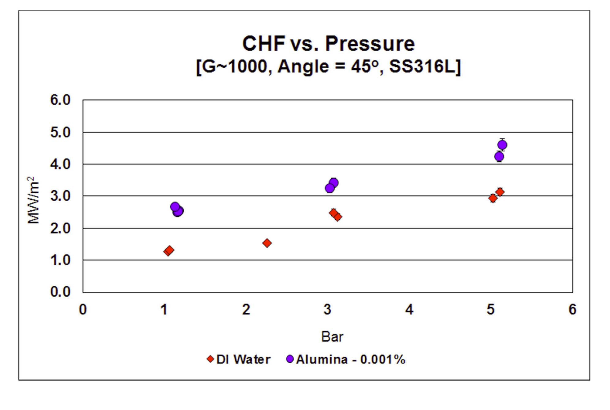
CHF data as a function of pressure for SS316L heaters
at G=1000 kg/m2-s and 45° orientation angle is plotted in Figure 8. CHF increases with increasing pressure both for water and alumina nanofluid, as is expected at these modest pressures. Relative CHF enhancement decreases
with increasing pressure, but absolute enhancement is fairly constant.
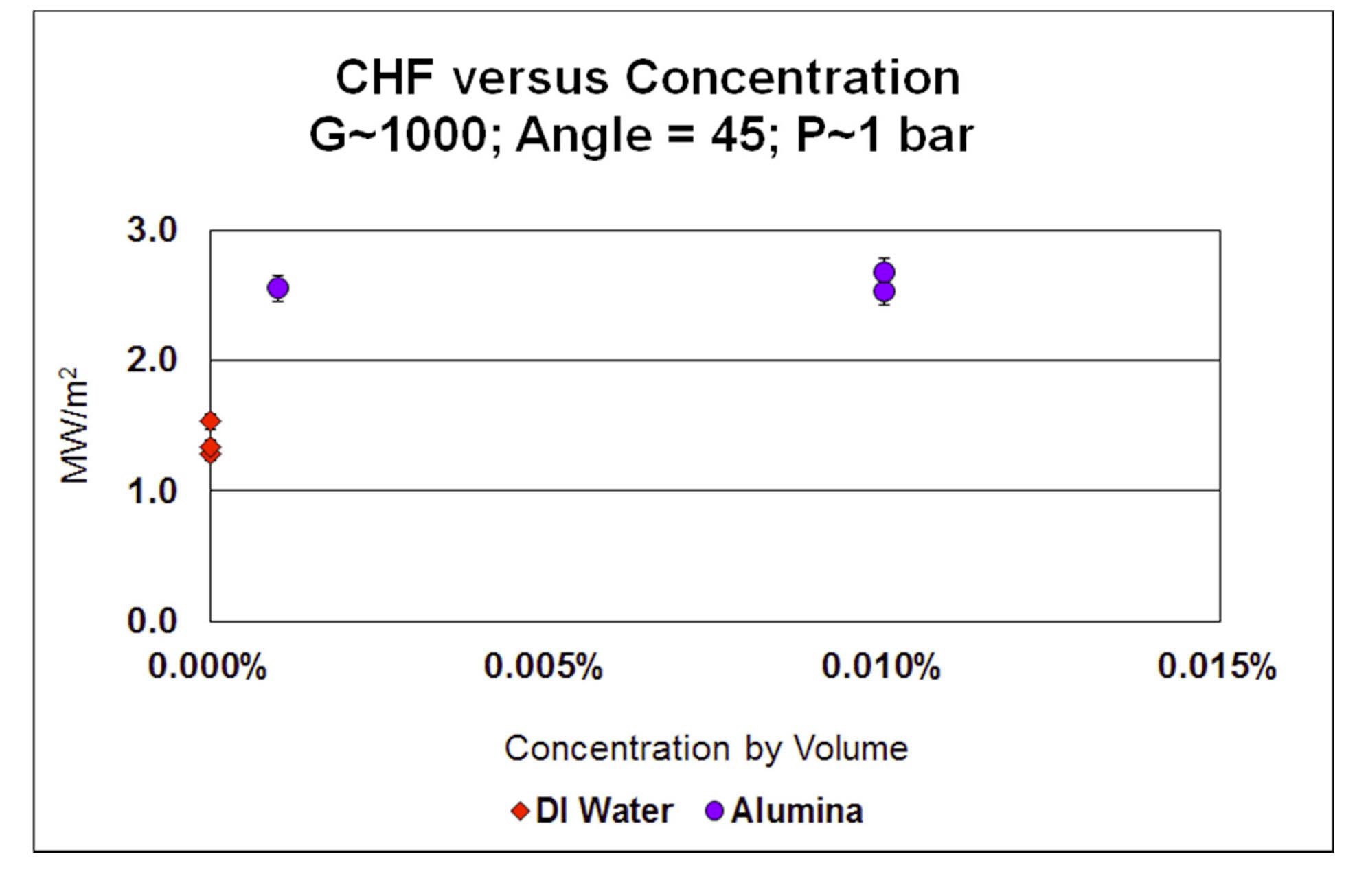
The effect of nanoparticle concentration on CHF is shown in Figure 9 for SS316L heaters, at 1 bar, G=1000
kg/m2-s and θ=45°. There seems to be no effect of concentration in the 0.001%-0.01% vol. range.
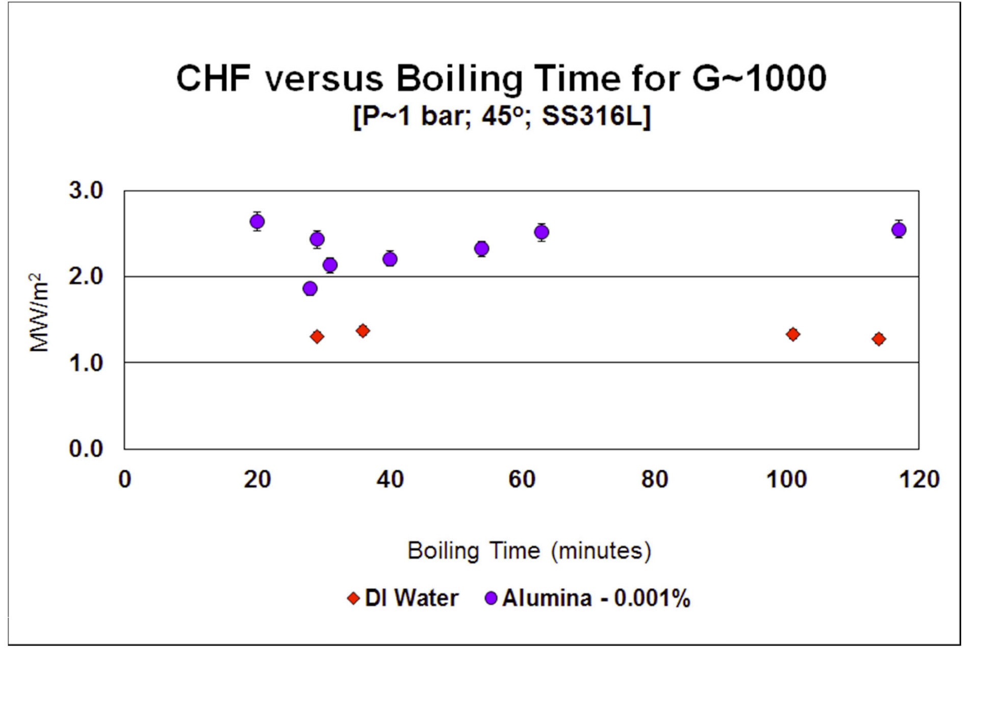
Most experiments involved in excess of 1½ hours of boiling time during the heat flux ramp-up to CHF. Since CHF enhancement is related to nanoparticle deposition [35], it was decided to investigate the effect of boiling time on nanofluid CHF. The normal test procedure was modified so to limit heater surface boiling time to a target short time, from 20 to 54 minutes (see Figure 10). Although there was a little bit of data scatter at low boiling times, CHF enhancement did not seem to be reduced at low boiling times. Basically, ½hour of boiling with alumina 0.001% nanofluid assured sufficient nanoparticles deposition onto the surface and enhancement of CHF. Reduced boiling time for water had no effect on CHF, as expected. Note that the IVR strategy has a time frame of hours, corium development is expected to take at least 2 hours, so there is plenty of time to inject a nanofluid and let nanoparticle deposition take place before the high CHF is needed for IVR [1][2].
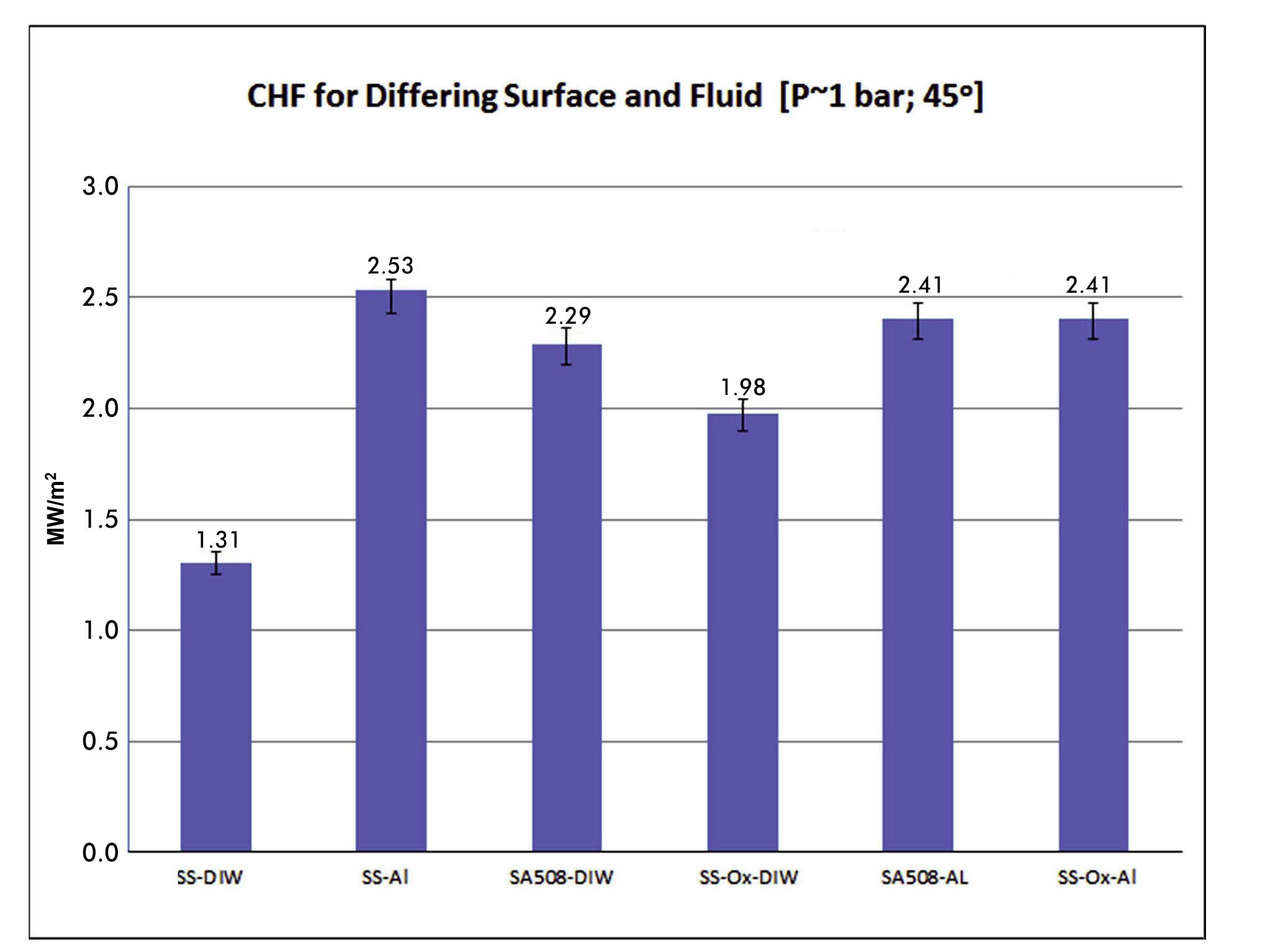
The effect of heater material (stainless steel 316L vs. carbon steel SA-508) and surface finish (pre-oxidized at 800℃; for 1 hour vs as-received) was also investigated, as shown in Figure 11, for 1 bar, G=1000 kg/m2-s and θ=45°. The CHF of SS316L increases greatly when the surface is pre-oxidized and even further when the nanofluid is used. On the other hand, the nanofluid does not seem to have any effect on CHF for SA-508, which is heavily corroded during the boiling tests, even in the absence of nanoparticles, and thus has a high CHF to begin with.
It is likely the joule heating of the sample heater accelerates the rate of corrosion on the SA-508 heater surface. It is well known that electrical potential drives corrosion rates and regimes. Voltage drop during boiling is several volts, when potentials of only mV are needed to accelerate corrosion. For IVR the question then becomes how much oxide scale would be present prior to an event and how much would be formed during the event. The presence of an oxide seems to be of benefit to CHF relative
to a clean surface and a nanofluid does not lower it. If little or no oxidation is present on the lower head of the vessel then the nanofluid is likely to increase CHF. If high oxidation on SA-508 is already present, the alumina would have little or no influence on CHF. CHF testing of SA- 508 with cartridge heating could be used to remove the influence of an over voltage at the surface fluid interface and is recommended for future work.
Four types of surface measurements were completed to better understand nanofluid deposition during boiling in IVR conditions and the resulting influence on CHF: Energy Dispersive Spectroscopy (EDS), Scanning Electron Microscopy (SEM), confocal microscopy and contact angle measurement. It should be noted that the physical properties of the nanofluids at the low concentrations tested herein are nearly identical, within measurement uncertainty, of DI water, as shown in [40]. Therefore any significant CHF enhancement must be from surface influences, either chemical or physical.
EDS is used to identify the elemental composition of the heater surface. EDS takes advantage of the unique energy spectrum response of X-rays emitted from constituent elements due to excitation by a high-energy electron beam. For the as-received SS316L heater, the detected peaks are dominated by iron, chromium and nickel, the main components of stainless steel. When the heater is boiled in alumina nanofluids, nanoparticles deposition is sufficient to screen the iron-chrome-nickel substrate, and thus only the aluminum and oxygen peaks of alumina dominate.
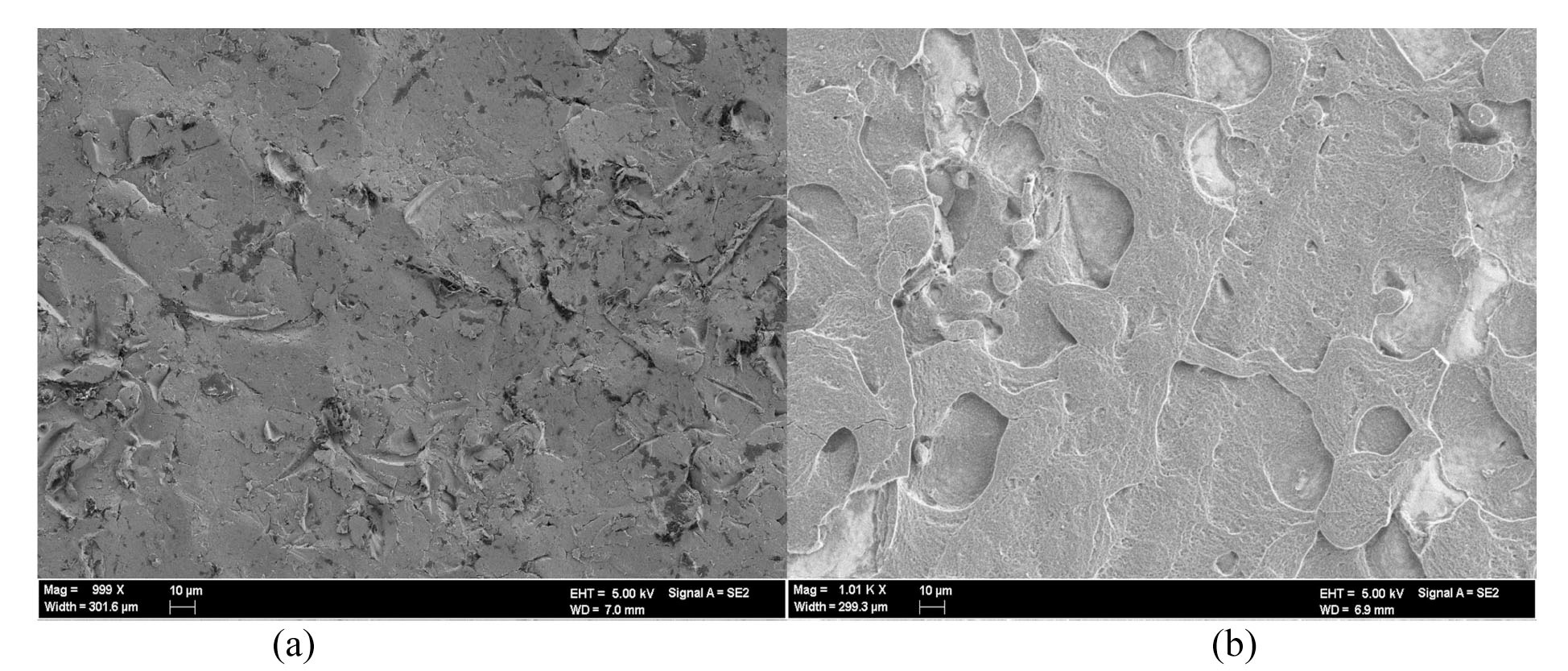
SEM images near 1000X for SS316L are shown in Figure 12, which visually confirms that nanoparticles
Confocal Microscope Measurements for SS316L heaters (two locations analyzed for each sample, both before the location of CHF but outside the region blackened by CHF.)
deposit onto the surface during the boiling process thereby changing the morphology of the surface. The deposit is fairly compact, with no noted breaks to the underlying metal, consistent with previous MIT findings [42]. The chemical and morphologic changes to the surface have an impact on wettability, which is quantified by contact angle measurement.
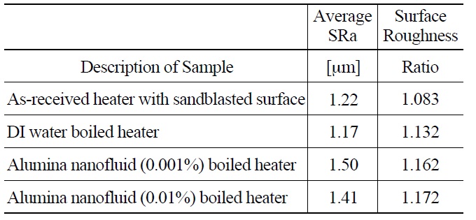
Confocal microscopy provided a second means of understanding surface topography and allowed for quantitative measurement of roughness, SRa (=arithmetic average of surface peak to valley amplitude), and surface roughness ratio (=actual surface area over projected area). The results are shown in Table 3. In spite of one order of magnitude difference in nanoparticle concentration, the two nanofluid cases have very similar average surface roughness, in the range of 1.4-1.5 μm, only about 20% greater than the DI water cases. The nanofluid cases also have very similar surface roughness ratios. This would suggest that similar surface morphology resulted from the deposition of the nanoparticles in both cases, which is also consistent with the fact that the CHF values for the two concentrations were similar (Figure 9).
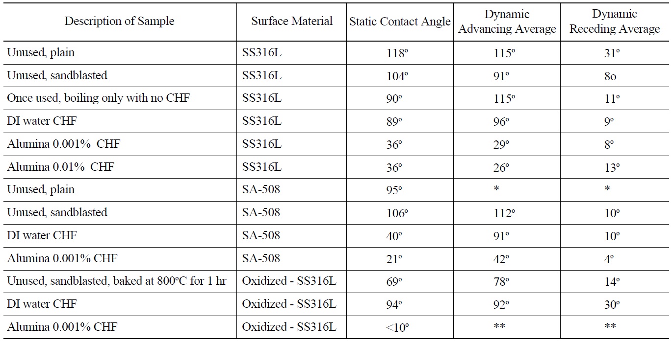
Research recently completed at MIT has demonstrated the importance that surface wettability has on boiling heat transfer and CHF [40]. Wettability is a measure of the affinity a liquid has to a solid surface [43]. The higher the wettability (lower contact angle) the faster liquid will rewet an uncovered (dry) spot, thus increasing CHF. To quantify wettability on surfaces used herein contact angle measurements were made. Both static and dynamic (advancing and receding) contact angles were measured, using videos of droplets fed or depleted by a fine syringe. A KSV Instrument Ltd. Model CAM101 contact angle and optical measurement device was used for these measurements. Uncertainty for contact angle measurement is ±5°. All contact angle measurements were done at room temperature with DI water. Both SS316L and SA-508 samples were measured. The results are shown in Table 4. A significant decrease in contact angle (both static and dynamic) is noted for alumina nanofluid boiled samples compared to DI water boiled samples for SS316L. On average static contact angle for DI water CHF test heaters is 89o. Average static contact angle for alumina nanofluid boiled heaters is 36°. The associated increase in wettability supports higher CHF. A second observation is that for SA-508 surface that was used in a DI water CHF test the contact angle is about the same as for the alumina nanofluid tests for SS316L. This implies that the SA-508 surface during boiling is modified, likely from corrosion, such that contact angle is significantly reduced. This may explain the high CHF value obtained relative to SS316L for similar conditions. Note that the alumina nanoparticle concentration does not seem to have an effect on the contact angle of these corroded SA-508 heaters. Finally, the pre-oxidized SS316L heater had a
[Table 4.] Static and Dynamic Contact Angle Measurements

Static and Dynamic Contact Angle Measurements
somewhat lower static contact angle of 69° compared to 102° for a prepared, unused SS316L heater.
The following conclusions can be made from this experimental study of the effect of water based nanofluids with alumina nanoparticles on CHF in IVR conditions:
The alumina nanofluids at 0.001% concentration by volume can increase CHF on average by 70% relative to water for SS316L heaters. CHF enhancement was measured for all orientation angles, pressures, and mass fluxes.
Increasing alumina concentration by a factor of ten to 0.01% by volume provides no additional CHF enhancement.
Boiling time of 30 minutes is sufficient to deposit nanoparticles onto the surface in sufficient amount to have meaningful CHF enhancement.
Carbon steel SA-508 has about the same CHF with DI water, 2.4 MW/m2, as stainless steel grade 316L with alumina nanofluid, 2.5 MW/m2 for the conditions tested. This higher CHF level is greater than studies completed by UCSB, Sultan and PSU that support the AP1000 licensing. It is hypothesized that the heavy corrosion that occurs during testing improves wettability on SA-508 and CHF. No CHF enhancement was measured on SA-508 with alumina nanofluid with 0.001% concentration by volume.
Pre-oxidized SS316L has a higher CHF, 2.0 MW/m2, than normally prepared SS316L with DI water, 1.3 MW/m2, for the conditions tested. Further CHF enhancement was observed, 2.4 MW/m2, on oxidized SS316L with alumina nanofluid with 0.001% concentration by volume nearly matching the normally prepared SS316L with alumina for the same conditions.
The CHF relative enhancement does not depend on orientation angle for mass fluxes above 1000 kg/m2-s. CHF and CHF relative enhancement are more sensitive to orientation angle at the lower mass flux, 500 kg/m2- s, for both water and nanofluids. The CHF for 500 kg/m2s mass flux of water increases by a factor of 3 as inclination angle increases from 0° to 90°. The CHF level for 1000 kg/m2s mass flux of water increases by ~50% as inclination angle increases from 0° to 90°. The CHF level for the 1500 kg/m2s mass flux of water does not increase as inclination angle increases from 0° to 90°.
The testing showed the trend that reduction in contact angle of the surface results in increased CHF.
To further the understanding of the influence that Alumina-water nanofluids have on CHF in IVR conditions for the AP1000 and improve the acceptance of conclusions made herein five (5) recommendations are made for future work. Tests could be readily designed to quantify the:
Impact that chemistry expected to be found in the working fluid during IVR might have on CHF. Example chemicals that may be present include boron and tri-sodium phosphate.
Minimum boiling time needed to set up the nanoparticle deposits on the surface.
Optimum nanoparticle size to enhance CHF.
Minimum nanofluid concentration that enhances CHF.
CHF enhancement as a function of the degree of surface oxidation.
Symbols
Bo - Bond number dimensionless
Cp - Heat capacity at constant pressure [kJ/kg-C]
De - Hydraulic diameter [m]
δ - Depth or thickness [m]
Fr - Froude number dimensionless
gc - Gravitational acceleration [m/s2]
G -Mass Flux [kg/m2-s]
hfg - Heat of vaporization [J/kg-℃]
Lb - Laplace length [m]
? - Mass Flow Rate [kg/s]
Mo - Morton number dimensionless
P -Pressure [bar]
q” - Heat flux [W/m2]
q”CHF - Critical heat flux [MW/m2]
ρ - Density [kg/ m3]
θ - Angle in x,z plane [degrees]
μ - Viscosity [Pa-s]
Re - Reynolds number dimensionless
σ - Surface tension [N-m]
σstd - Standard deviation
χe - Equilibrium quality dimensionless
V -Velocity [m/s]
We - Weber number dimensionless
Subscripts
e -equilibrium
f -saturated fluid
g -saturated vapor
l -liquid
v -vapor
Superscripts
o -degrees
“ -inches
Acronyms
CHF - Critical Heat Flux
CYBL - Cylindrical Boiling facility at Sandia National Laboratory
DAS - Data Acquisition System
DC - Direct Current
DI - De-Ionized water
DO - Dissolved Oxygen
DNB - Departure from Nucleate Boiling
EDS - Energy Dispersive Spectroscopy
IRWST- In-containment Refueling Water Storage Tank
IVR - In-Vessel Retention
LOCA - Loss of Coolant Accident
LWR - Light Water Reactor
MIT - Massachusetts Institute of Technology
NRC - Nuclear Regulatory Commission
PSU - Pennsylvania State University
ppm - Parts Per Million
SBLB - Subscale Boundary Layer Boiling facility at PSU
SEM - Scanning Electron Microscopy
UCSB - University of California, Santa Barbara
UCLA - University of California, Los Angeles


![CHF [q”chf] as a Function of Mass Flux [G] for SS316L Heaters at Atmospheric Pressure.](http://oak.go.kr/repository/journal/12385/OJRHBJ_2013_v45n3_335_f006.jpg)