Graphite has been widely used as a moderator, reflector, and fuel matrix in gas-cooled and Russian RMBK nuclear reactors. As a result, approximately 250,000 metric tons of irradiated graphite waste exists in various locations around the world [2]. Next generation reactor designs, such as the High Temperature Reactor (HTR), may use graphite coated fuel particles, a graphite reflector, and other graphite core structural components [5]. Deployment of HTRs will add significantly to the amount of irradiated graphite waste.
Characterization of existing irradiated graphite indicates the most significant long-lived radioisotope of concern is carbon-14 (14C), with a half-life of 5,730 years. This species is of concern for deep geologic disposal of irradiated graphite because it is readily mobile in groundwater and atmospheric systems [6]. Removal of 14C from the large irradiated graphite reactor components may prevent their costly disposal or even allow recycling of this very pure nuclear grade material [2].
Pyrolysis and oxidation have been suggested as 14C decontamination methods [4]. Fachinger
Partial oxidation, or gasification, of irradiated graphite via thermal treatment may prove a viable process for removing much of the 14C from graphite surfaces [6]. To optimize 14C removal, the removal pathway must be better understood. The efficiency of thermal treatment gasification is largely a factor of the adsorbed oxygen species that react with graphite carbon to form carbon oxide gases. As such, this paper focuses on surface characterization of graphites to determine the relative concentrations and bonding configurations of adsorbed oxygen-containing species.
2.1 Formation and Oxidation of 14C
As graphite is bombarded with neutrons in the reactor environment, 14C is produced through neutron capture by 13C, 14N, and 17O as shown in Table 1.
Characterization of irradiated reactor graphite has revealed a high concentration of 14C located on the surface. Inhomogeneous distribution of 14C in the graphite is indicative of neutron capture by 14N and 17O, rather than 13C. Because 13C is homogeneously distributed throughout graphite, it follows that 14C produced from 13C also would be homogeneously distributed. Graphite naturally adsorbs air; consequently, 14N and 17O are readily found on the graphite surface. Exposure to air occurs during graphite manufacturing, between manufacture and reactor insertion and during neutron irradiation via reactor coolant impurities. The neutron capture cross sections and isotopic abundances of 14N and 17O, as seen in Table 2, indicate the neutron activation of 14N is the more likely source of 14C on irradiated graphite surfaces.
14C created from 14N, rather than a 13C within the graphite structure, may have a chemical form different from the aromatic bonding in the graphite crystal structure. The chemical form of each graphite surface carbon, regardless of the isotopic identity (12C or 14C), will impact its oxidization, as will the quantity and type of oxygen species. The chemical form of surface 14C in irradiated graphite is the subject of a separate study and future publication.
Gasification of graphite occurs via a 3-step mechanism: (1) the primary adsorption of oxygen onto the graphite
[Table 1.] Neutron Capture Reactions Forming 14C [6]

Neutron Capture Reactions Forming 14C [6]
[Table 2.] Properties of 14C Precursors [7]
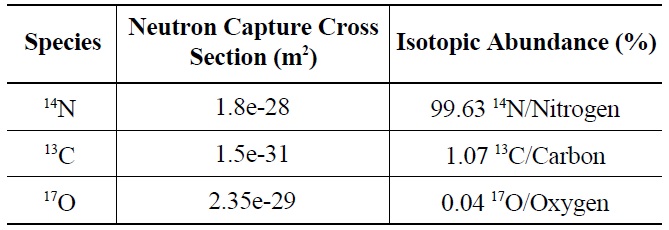
Properties of 14C Precursors [7]
surface, (2) the surface reaction between adsorbed oxygen and active carbon sites, and (3) desorption of the newly formed carbon-oxygen species [8]. Oxygen species adsorption and interaction with carbon active sites occurs spontaneously. Graphite crystal structural damage due to neutron irradiation significantly increases the number of active sites available to oxygen species both in the reactor (via coolant impurities) and out (via storage in air). Desorption of CO and CO2, the third step of gasification, is facilitated by thermal treatment.
In-reactor oxidation of graphite is a topic of great interest for reactor designs with regard to long-term performance (e.g. low level chronic oxidation) and safe operation during off-normal conditions (e.g. large air leak into He coolant stream) [9]. Oxidation under reactor conditions, however, is beyond the scope of this paper, which addresses out-of-core oxidation with special application to irradiated graphite waste treatment.
2.2 Theory of Characterization of Graphite Surface Species
Surface sensitive techniques, Time-of-Flight Secondary Ion Mass Spectrometry (ToF-SIMS) and X-ray Photoelectron Spectroscopy (XPS), were employed to characterize the oxygen complexes adsorbed on unirradiated and irradiated graphites.
ToF-SIMS allows identification and quantification of surface constituents at the parts-per-billion concentrations by detecting displaced charged atomic and/or molecular species with a mass spectrometer. Resulting data was interpreted to determine the elemental, isotopic, and molecular composition of the graphite surface.
XPS was used to verify the chemical environment of the oxygen compounds identified by ToF-SIMS. Samples are bombarded with x-rays, which impart their energy to eject core electrons. By measuring the energy of a removed electron, its atomic binding energy can be determined and consequently the identity of the atom. Binding energies are characteristic for each element, and are direct representations of the atomic orbital energies [10]. When outer electrons are shared via bonds with other atoms, the binding energies of inner, core electrons change to accommodate the new electronic environment. These energy changes, termed chemical shifts, often can be used to determine the type of bonding present. By measuring the binding energies of core electrons from oxygen atoms, it is possible to discriminate between different bonding modes of chemisorbed oxygen-containing molecules [11].
3.1 Graphite Properties and Preparation
Two types of graphite, nuclear grade NBG-18 and a highly porous graphite foam (POCOFoam®, POCO Graph-ite,
[Table 3.] Properties of Graphite Samples
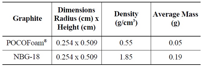
Properties of Graphite Samples
INC.), were selected for this experiment. Samples were cut from larger blocks of each type into small cylinders with dimensions 0.48 cm high by 0.848 cm in diameter as summarized in Table 3. Before and after irradiation, samples were handled with latex gloves or forceps and were stored in an air environment at ambient pressure.
NBG-18 is an isotropic graphite (density = 1.85 g/cm3), which exemplifies the type used for neutron reflector and structural material in an HTR design [12]. POCOFoam® was chosen for its significant surface area (density = 0.55 g/cm3), which adsorbs more nitrogen than less porous graphites. It was speculated that higher nitrogen concentrations would result in the production of more 14C upon irradiation. while total 14C concentrations existing on irradiated reactor graphite are significant, the concentration found on a typical characterization sized sample would be on the order of parts-per-billion, which is too low for meaningful characterization. To further increase the quantity of 14C produced, graphite samples were immersed in liquid nitrogen for twenty-four hours prior to being sealed in a canister for neutron-irradiation. Irradiation took place at the MURR research reactor at the University of Missouri for 120 days in a thermal neutron flux of 6.7 x 10²⁰ neutrons /cm2/s. Resulting 14C activity was approximately 4.06 x 10³ Bq/g.
Unirradiated and irradiated samples of each graphite type were characterized and compared.
To identify adsorbed species, graphite sample surfaces were analyzed via ToF-SIMS (TRIFT I spectrometer by PHI-EVANS). During analysis, samples were kept in a constant ultra-high vacuum environment of 1.29 μPa to reduce contamination in the chamber. The focused primary ion beam was rastered over an area of 100 μm2 on the sample surface. Secondary ions were measured from a smaller region of 20 μm2 located at the center of the sputtered area. The accelerating voltage was set to 15.03 keV in the primary gallium ion source and -3 keV on the sample surface, resulting in a net voltage of 12.03 keV. Sputtering at a rate of 0.022 nm/sec allowed special variations in carbon-oxygen containing functional groups to be measured. Data was analyzed using WinCadence Version 3.41 to identify adsorbed oxygen functional groups and their relative concentrations.
To learn more about the bonding nature of species identified via ToF-SIMS, graphite samples were studied via XPS using a VersaProbe PHI 5000 spectrometer with Aluminum Kα radiation (1480.6 eV) and a base pressure of 45.3 nPa. To measure the chemical shifts in the electron binding energy of the chemisorbed oxygen compounds, the O 1s core level spectrum was recorded. To ensure accuracy the energy scale was calibrated to reproduce the binding energies of Cu 2p3/2 (932.65 eV) and Au 4f7/2 (84.00 eV) and the sample charging was corrected by aligning the C 1s peak to 284.8 eV. Changes in the atomic concentrations, bonding configurations, and electronic structures of the target species were observed while sputtering the samples at a rate of 0.025 nm/sec. The core level spectra were fitted using least-squares in AugerScan 3. To provide the sharpest O 1s peak and a near Gaussian fit, the data were filtered to yield a full-width-half-mass of less than 1.8 eV. The O 1s spectra were further resolved into component peaks also using AugerScan 3. These analyses allowed for the determination of the chemical composition, bonding configurations, and electronic structure of the samples.
Adsorbed oxygen species identified by ToF-SIMS analysis of unirradiated POCOFoam® and NBG-18 graphite samples are shown in Table 4.
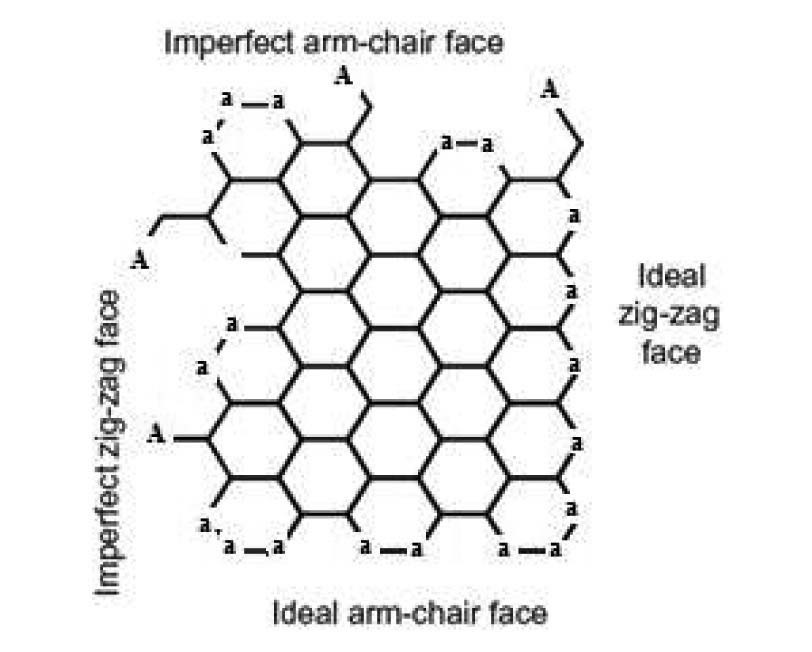
Elemental oxygen (16O) was the most abundant chemical species identified on POCOFoam®, while the most abundant chemical species found on NBG-18 was H3O. As expected, POCOFoam® adsorbed more species than NBG-18 due to its larger surface area. No carbon-oxygen species were detected from either graphite. Because O2 typically dissociates when chemisorbed, the presence of 16O is indicative of chemisorption; therefore, it is probable that the oxygen compounds are loosely chemisorbed to active sites within the graphite ring, such as those denoted by “a” in Figure 1 [4,13]. Prior to irradiation the graphite lattice is highly ordered and likely has minimum imperfections. After irradiation, the number of imperfections, and associated active sites, is larger. The active sites (labeled “A” in Figure 1) associated with imperfections in the graphite lattice have higher electron affinities leading to stronger chemisorbed carbon-oxygen bonds.
The ToF-SIMS spectra for irradiated POCOFoam® and NBG-18 graphites were used to identify and quantify the oxygen-containing species shown in Table 5.
Results indicated 16O concentration is significantly less in the irradiated graphite than the unirradiated. Adsorbed carbon-oxygen compounds were detected on the irradiated graphite, which may indicate oxygen is more strongly
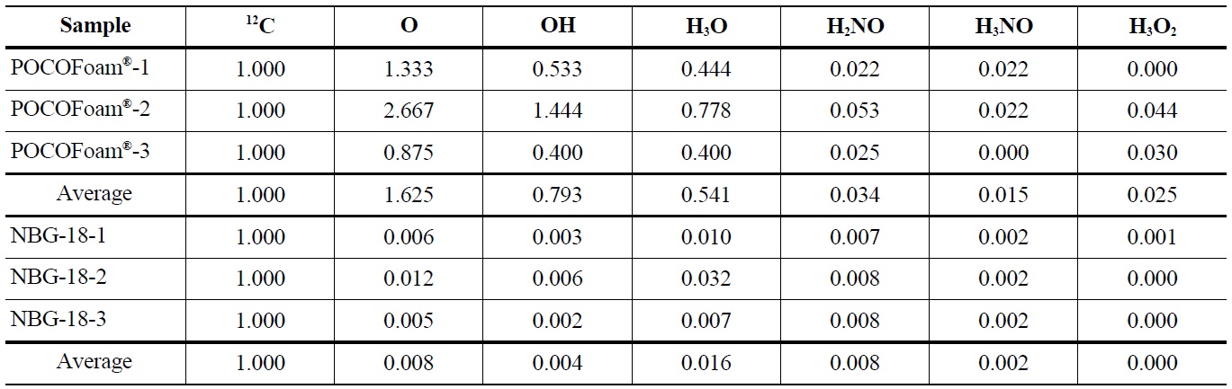
Concentrations of Oxygen Containing Fragments with Respect to Ejected Carbon-12 from Unirradiated POCOFoam® and NBG-18 Graphites
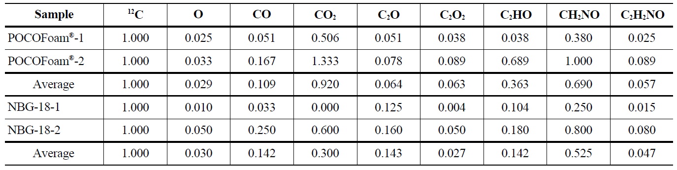
Concentrations of Oxygen Containing Fragments with Respect to Ejected Carbon-12 from Irradiated POCOFoam® and NBG-18 Graphites
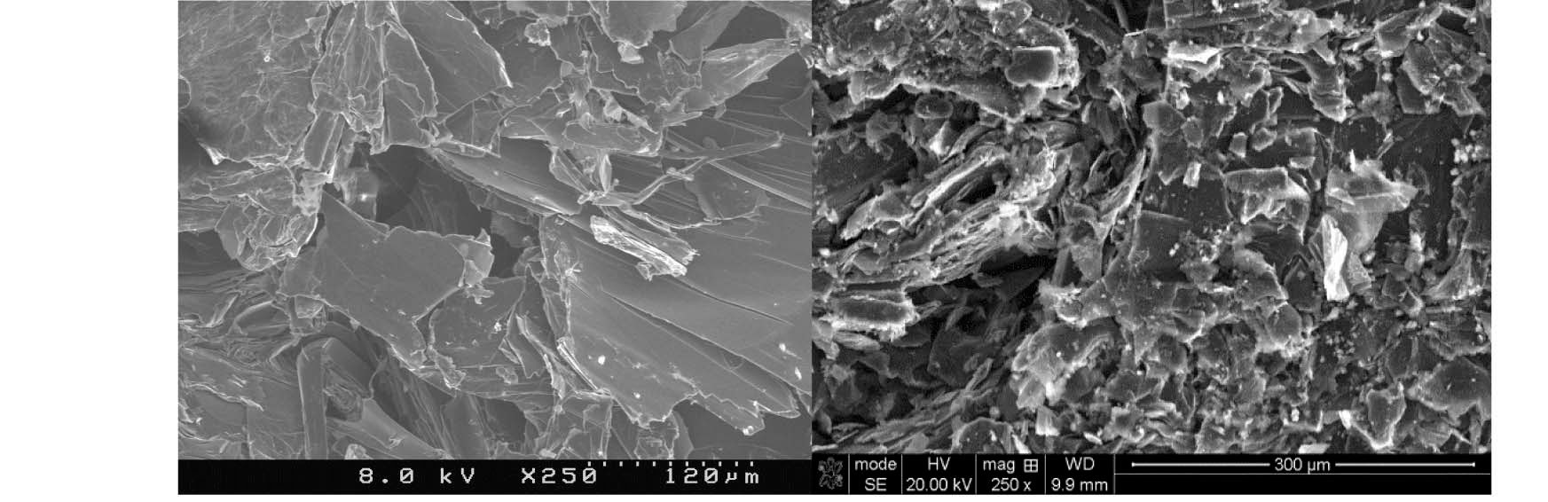
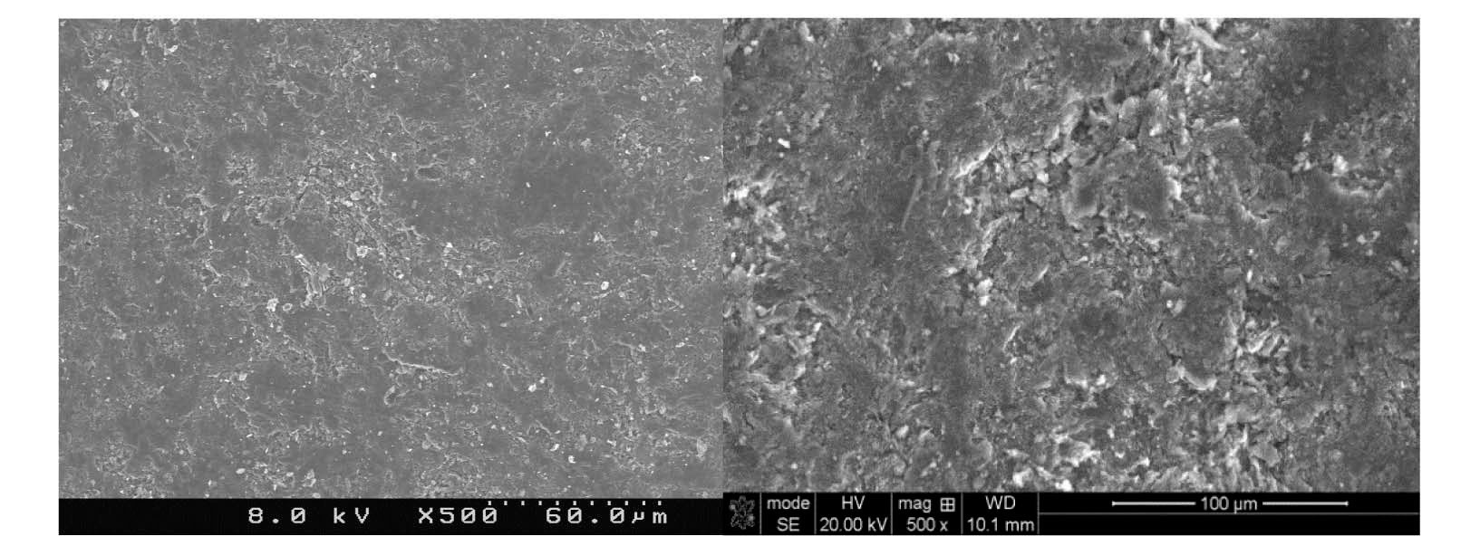
bound to the graphite surface upon irradiation. A significant increase in lattice imperfections as a result of irradiation damage likely causes the formation of strong carbonoxygen bonds. This theory is supported by SEM (Scanning Electron Microscopy) images of POCOFoam® (Figure 2) and NBG-18 (Figure 3) graphites before and after irradiation.
POCOFoam® graphite has by nature a more disordered structure than nuclear grade graphites. Nonetheless, at a magnification of 250x, there is as notable, qualitative difference between the morphologies before (Figure 2, Left) and after irradiation (Fig. 2, Right). This difference is attributed to radiation damage that causes fragmentation of the surface and is consistent with previous findings on irradiation damage to graphite [8].
The small number and size of pores in unirradiated NBG-18 graphite (Figure 3, Left) are a result of the manufacturing process. Because of the fine-grain nature of this graphite, it was necessary to use higher magnification than used for the POCOFoam® to see the irradiation effects. In the post-irradiation image (Figure 3, Right) there is evidence of “scaling” of the outermost surface from the underlayers of the material.
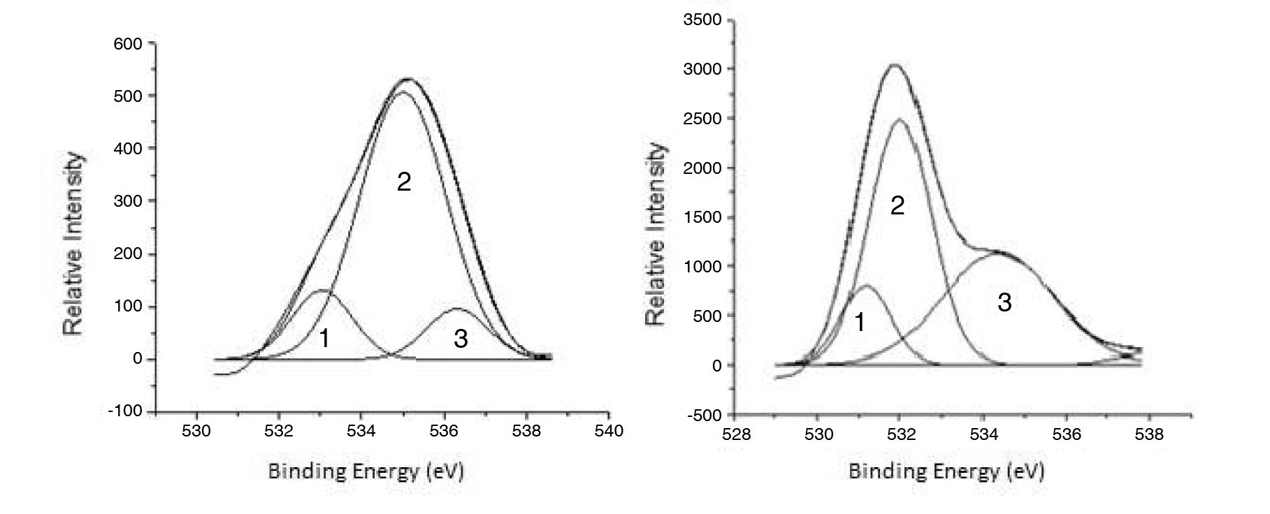
Using XPS, the adsorbed oxygen compounds were further evaluated. The deconvolution of the O 1s XPS spectra for POCOFoam® and NBG-18 graphites can be seen in Figures 4a and 4b.
Deconvolution of the O 1s irradiated POCOFoam® spectra identified three peaks: peak 1 (533.04 eV), indicative of non-carbonyl (ether-type) oxygen atoms in esters;
peak 2 (535.00 eV), oxygen atoms in carboxyl groups; and peak 3 (536.32 eV), which corresponds to adsorbed water and/or oxygen [14]. These results are summarized in Table 6. Similarly, deconvolution of the O 1s irradiated NBG-18 spectra identified three peaks: peak 1 (531.18 eV), indicative of oxygen atoms from C=O in carboxyl and/or carbonyl groups; peak 2 (532.01 eV), carbonyl oxygen atoms in esters, anhydrides, and/or oxygen atoms in hydroxyl groups; and lastly peak 3 (534.38 eV), oxygen atoms in carboxyl groups [14]. These results are summarized in Table 7.
The main difference between XPS spectra for the two graphites is the presence of oxygen and/or water on POCOFoam ®. While 16O was not detected via XPS analysis of NBG-18 graphite, it was detected on both graphites via ToF-SIMS. An inhomogeneous surface distribution of 16O is the likely reason for this discrepancy.
4.3.1 Carbon, Nitrogen, and Oxygen Surface Species
The functional groups identified via ToF-SIMS and XPS analyses are likely fragments of adsorbed compounds, rather than the complete absorbed species themselves. The nature of these surface species is a key factor impacting the mechanisms and rates of graphite oxidation. Fanning and Vannice [3] have identified numerous oxygen-containing functional groups on carbon (carbon black and char) surfaces.
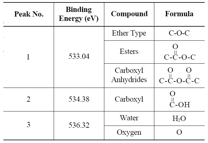
Probable Oxygen Functional Groups Adsorbed on Irradiated POCOFoam® Graphite as Determined from XPS O 1s Deconvolution Spectrum
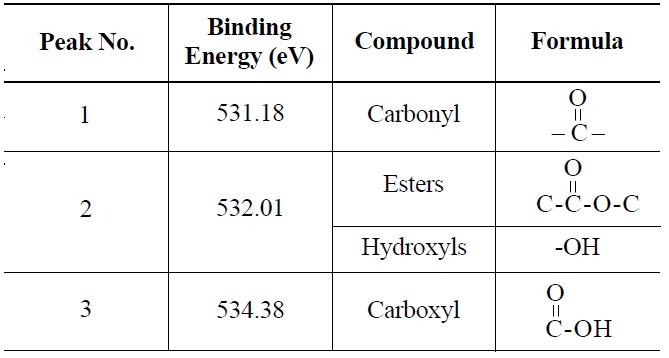
Probable Oxygen Functional Groups Adsorbed on Irradiated NBG-18 Graphite as Determined from O 1s Deconvolution Spectrum
Diffuse Reflectance Fourier Transform Infrared Spectroscopy (DRIFTS) was used to study the progressive oxidation of carbon surfaces initially free of all oxygen species. First formed were cyclic ethers (=C?O?C=), which rearranged on further oxidation to form ether-like links between polyaromatic domains. With still further oxidation, there was evidence of cyclic anhydrides, lactones, quinones, ethers and phenols. Although these carbon materials (carbon black and char) have significantly different bulk properties (e.g. amorphous nature, high impurities) than nuclear grade graphite, the fundamental carbon and oxygen bonding information is transferrable. The less pure carbon materials may serve as a conservative analogy for nuclear graphite, especially after neutron irradiation.
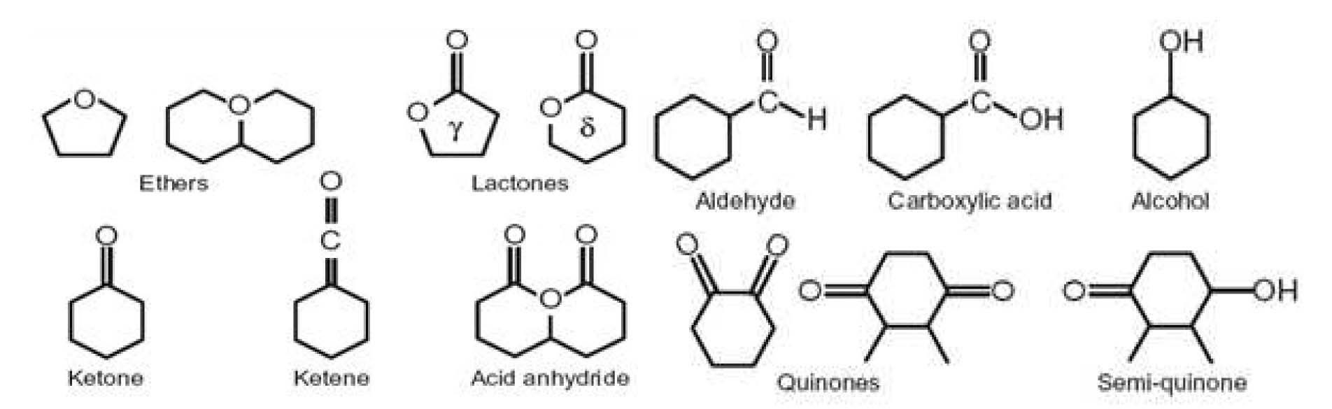
El-Genk and Tournier [4,15] have developed a model for the chemical kinetics of graphite oxidation. The model incorporates likely chemical forms of adsorbed oxygen species consistent with Fanning and Vannice (See Figure 5) [3]. The compounds identified by ToF-SIMS and XPS, reported above, are in keeping with the model. ToF-SIMS also indicated the presence of nitrogen-containing species CH2NO and C2H2NO, possibly amides. It is likely that formation of these species was enhanced by the pre-irradiation immersion of the experimental graphite in liquid nitrogen; however, nitrogen-containing products are present with oxidation of any carbon exposed to air. Indeed, Miessen
4.3.2 Surface Species and Graphite Oxidation
Adsorbed oxygen functional groups and active sites on the graphite surface have different stabilities and activities. Consequently, carbon oxides, primarily CO or CO2, will desorb at different rates upon heating [4,6]. As gasification proceeds the microstructure changes significantly, which also affects the desorption rate, pathway, and speciation. The avulsion of CO results from the direct release from an ether or carbonyl; after the decomposition of an ether, ketene, or aldehyde; or when released after the gasification of carbon atoms neighboring ethers, lactones, and anhydrides [4]. CO2 could avulse from esters, C2O2 complexes (see Table 5), and carboxyl-anhydrides (see Table 6). However, the majority of CO2 likely desorbs after surrounding carboncarbon bonds are weakened by the chemisorptions of an oxygen on a neighboring quinone or semi-quinone complex. While CO could also desorb from a quinone complex, the activation energy required to remove CO from the quinone complex is quite high [11].
Based on these CO and CO2 production pathways, the ratio of CO/CO2 released can be directly manipulated via thermal treatment temperature. Because CO2 largely desorbs after the breaking of carbon-carbon bonds neighboring quinone and semi-quinone complexes, the ratio of CO/CO2 removed would be lowered by heating the graphite at temperatures below the surface decomposition temperature (~1000) [4,17]. Compounds identified by ToFSIMS and XPS indicate the majority of desorption is expected as CO instead of CO2. Therefore, to optimize the efficiency of thermal treatment the process should be performed above the surface decomposition temperature.
Carbon-14 is a concern for the long-term disposal of irradiated graphite. Optimizing thermal treatment to remove surface 14C may offer a unique, effective solution to irradiated graphite waste. Because thermal treatment is greatly affected by the nature and concentration of available oxygen, oxygen-containing species adsorbed on graphite surfaces are of interest. Surface analyses of unirradiated and irradiated POCOFoam® and nuclear grade NBG-18 graphites were performed. Oxygen-containing functional groups identified by ToF-SIMS analysis were confirmed and further characterized via XPS.
On the unirradiated graphite surfaces, elemental oxygen was a dominant species. Some oxygen bonding with hydrogen and nitrogen was evident, but no carbon-oxygen bonds were detected. It was expected that neutron irradiation damage to the graphite crystalline structure would increase the number of carbon active surface sites, thereby resulting in carbon-oxygen bonds. Indeed, this phenomenon was observed. Ester-like (O-C=O) bonding dominated for species on irradiated POCOFoam® surfaces and such species had the second largest concentration of those on irradiated NBG-18. The dominant fragment identified on the irradiated NBG-18, and second most prevalent on irradiated POCOFoam ®, contained carbon, hydrogen, nitrogen and oxygen in the empirical ratios 1:2:1:1. Carboxyl group species were detected on both irradiated graphite types.
The identified oxygen functional groups are consistent with those identified by earlier researchers (3,16) as the chemical forms of oxygen complexes adsorbed on carbon materials. The quantification and speciation of carbonoxygen fragments on POCOFoam® and NBG-18 indicates the majority of compounds will desorb as CO during gasification. Therefore to optimize thermal treatment the process should be performed at temperatures above the surface decomposition temperature.

![Neutron Capture Reactions Forming 14C [6]](http://oak.go.kr/repository/journal/12374/OJRHBJ_2013_v45n2_211_t001.jpg)
![Properties of 14C Precursors [7]](http://oak.go.kr/repository/journal/12374/OJRHBJ_2013_v45n2_211_t002.jpg)


![Configurations of Graphite and Active Sites [4]](http://oak.go.kr/repository/journal/12374/OJRHBJ_2013_v45n2_211_f001.jpg)


![Plausible Compounds Formed by Oxygen Adsorption on Graphite Surface as Incorporated in the Model by El-Genk and Tournier [4,15].](http://oak.go.kr/repository/journal/12374/OJRHBJ_2013_v45n2_211_f005.jpg)