The objective of this conducted research is to study the iodine removal efficiency in a self-priming venturi scrubber for submerged and non-submerged operating conditions experimentally and theoretically. The alkaline solution is used as an absorbent, which is prepared by dissolving sodium hydroxide (NaOH) and sodium thiosulphate (Na2S2O3) in water to remove the gaseous iodine (I2) from the gas. Iodine removal efficiency is examined at various gas flow rates and inlet concentrations of iodine for submerged and non-submerged operating conditions. In the non-submerged venturi scrubber, only the droplets take part in iodine removal efficiency. However, in a submerged venturi scrubber condition, the iodine gas is absorbed from gas to droplets inside the venturi scrubber and from bubbles to surrounding liquid at the outlet of a venturi scrubber. Experimentally, it is observed that the iodine removal efficiency is greater in the submerged venturi scrubber as compare to a nonsubmerged venturi scrubber condition. The highest iodine removal efficiency of 0.99±0.001 has been achieved in a submerged self-priming venturi scrubber condition. A mathematical correlation is used to predict the theoretical iodine removal efficiency in submerged and non-submerged conditions, and it is compared against the experimental results. The Wilkinson et al. correlation is used to predict the bubble diameter theoretically whereas the Nukiyama and Tanasawa correlation is used for droplet diameter. The mass transfer coefficient for the gas phase is calculated from the Steinberger and Treybal correlation. The calculated results for a submerged venturi scrubber agree well with experimental results but underpredicts in the case of the nonsubmerged venturi scrubber.
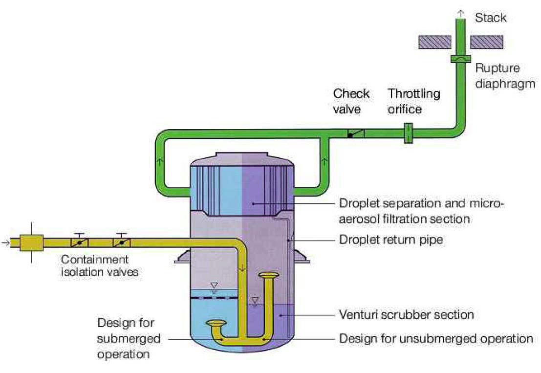
In the case of a severe accident at a Nuclear Power Plant (NPP), the core is melted down due to loss of coolant. As a result, fission products are released from the fuel into the containment. NUREG-1465 specify the iodine fission product released to the containment has iodine in various chemical forms and percentages, i.e. CsI 95%, I plus HI 5%, and I and HI with not less than 1% [6]. Due to its strong radiological effects, it can affect human health as well as the environment if it cannot be contained. Therefore, it is necessary to remove the iodine from the contaminated gas due to these hazardous effects. For this purpose, Filtered Vented Containment System (FVCS) comprising of venturi scrubbers and metallic fiber filter was installed in the NPP [2] as shown in Figure 1. These venturi scrubbers cleaned the contaminated gas, and collected the radioactive iodine by its absorption process using scrubbing liquid.
The venturi scrubber is one of the most popular choices for engineers and scientist since the mid-20th century during and used for cleaning of contaminated gas. The venturi scrubber successfully removes submicron particles and gaseous pollutants simultaneously from the gas stream via droplets within the short contact time between the liquid
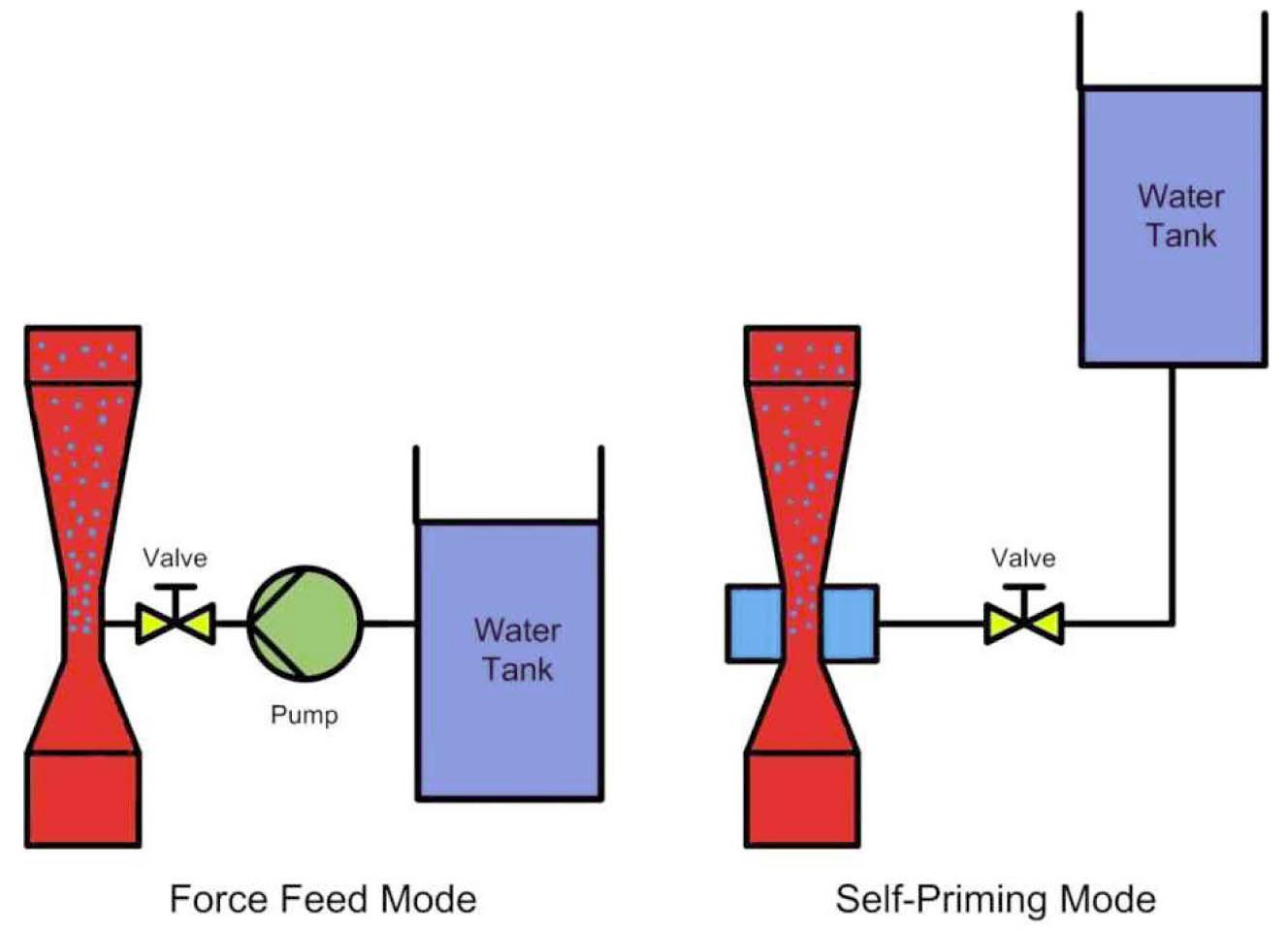
and gas phases. The submicron particles are captured while the gaseous pollutants are absorbed by the liquid. The venturi scrubber mainly consists of three sections: a convergent section which accelerates the gas to its maximum velocity; a throat section between convergent and divergent parts, where gas and liquid interact with each other and finally a diffuser section, where the fluid velocities decelerate for pressure recovery [4]. There are two methods to provide liquid into the venturi scrubber; the forced feed method through pumps and the self-priming method based upon the pressure difference between the hydrostatic pressure of the liquid in the tank and static pressure of the gas in a venturi scrubber [7]. The difference between a forced feed method and a self-priming venturi scrubber is shown in Figure 2. The liquid is introduced at the convergent or at the throat section in the jet, in either a film or spray form. The interaction of gas and liquid takes place at the throat section, where high velocity gas disintegrates the liquid into an enormous number of tiny droplets. The self-priming venturi scrubber is relatively simple, occupies less space, has no rotating parts, handles high-temperature, has no operating cost and removes dust and gaseous pollutants simultaneously. The major drawbacks include treatment of liquid effluents [1].
Lehner studied the operating condition, liquid crumbling, and collection efficiency of a self-priming venturi scrubber. Liquid was introduced in the form of a jet. It was observed that the aerosol separation efficiency was enhanced by injecting liquid at multistage [7]. Hills developed the solutions with the different boundary conditions for the mass transfer in a venturi scrubber. The solution considers the first-order chemical reaction. The boundary condition used to find the solutions were: surface concentration constant, absorption from a limited volume of a gas, external mass transfer resistance with constant bulk gas concentration, gas-phase mass-transfer resistance and finite gas volume, and infinitely rapid reaction [3]. The results were compared with the experimental data of Ravindram
et al. [9] and found serious disagreement. Gamisans studied the mass transfer of sulphur dioxide into aqueous sodium hydroxide solution in a jet venturi scrubber. The study was based on two different atomizers, different throat length and diameter. Gamisans developed the mathematical model based on Hills's solution. The results were compared with the theoretical model for concentration of pollutants in a venturi scrubber [15].
The aim of this research is to study the iodine removal efficiency in the submerged and non-submerged selfpriming venturi scrubber for different inlet concentration and gas flow rate and compare the experimental results with theoretical model.
The rest of the paper is organized as follows. Section 2 explains the mathematical model for iodine removal efficiency in a non-submerged and submerged venturi scrubber. Section 3 explains the experimental facility for iodine removal efficiency. In Section 4, the results obtained from the experiment and model is discussed. Section 5 summarizes this conducted research work.
2.1 Model for Non-Submerged Self-Priming Venturi Scrubber
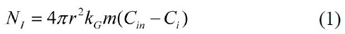
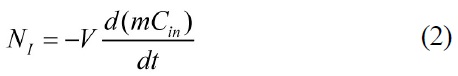
A mathematical model for iodine absorption in droplets based on the two film theory is proposed. In this model, the driving force is the concentration difference of iodine whereas the mass transfer phenomenon will take place at an interface. The reaction rate is assumed to be kinetically rapid. The rate of mass transfer in a droplet is a gas film controlled reaction, which is given as [15],
The equation of mass balance for a gas surrounding the droplet is [15],
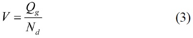
The volume of gas surrounding the droplet is calculated from the following equation,
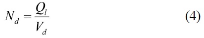
Whereas the number of droplets generated at a given flow rate is determined from the given equation,
The condition Ci = 0 is assumed because of the reaction being totally gas film controlled and reaction lying on the interface. The similar maximum molar rate can be supplied to interface at the concentration of absorbents by diffusion through the liquid and concentration of iodine by diffusion through the gas [3].
By comparing equation 1 and 2 and then integrating it, we get the following equation;
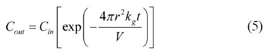
where contact time of droplet with iodine gas in the venturi scrubber is calculated as [9];
The gas-phase mass transfer coefficient for a single droplet is calculated by Steinberger and Treybal’s correlation [13] and the valid ranges of this correlation are 1

where
Nukiyama and Tanasawa correlation is used to measure the mean size of droplet [14],
The iodine removal efficiency for a non-submerged venturi scrubber is calculated from the following expression;
2.2 Model for Submerged Self-Priming Venturi Scrubber
The iodine removal efficiency in submerged selfpriming venturi scrubber depends on the droplets in venturi scrubber and bubbles produced in a venturi tank when gas leaves at the outlet of a venturi scrubber. The model for non-submerged venturi scrubber is used to calculate the iodine removal efficiency in droplet, and bubble. The diameter of the bubble is calculated from the following equation [12],
where contact time is given as,
The mass transfer coefficient from bubbles to the surrounding liquid in the water bed is calculated from Equation 6, where Sherwood and Reynolds number is calculated as below,
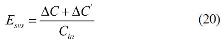
The iodine removal efficiency for a submerged venturi scrubber in a venturi scrubber is calculated from the following expression;
The outlet concentration or escaped concentration from a venturi scrubber will be an inlet for the water bed. The removal efficiency calculated in the water bed is given as;

The total iodine removal efficiency for a submerged venturi scrubber is calculated from the following expression;
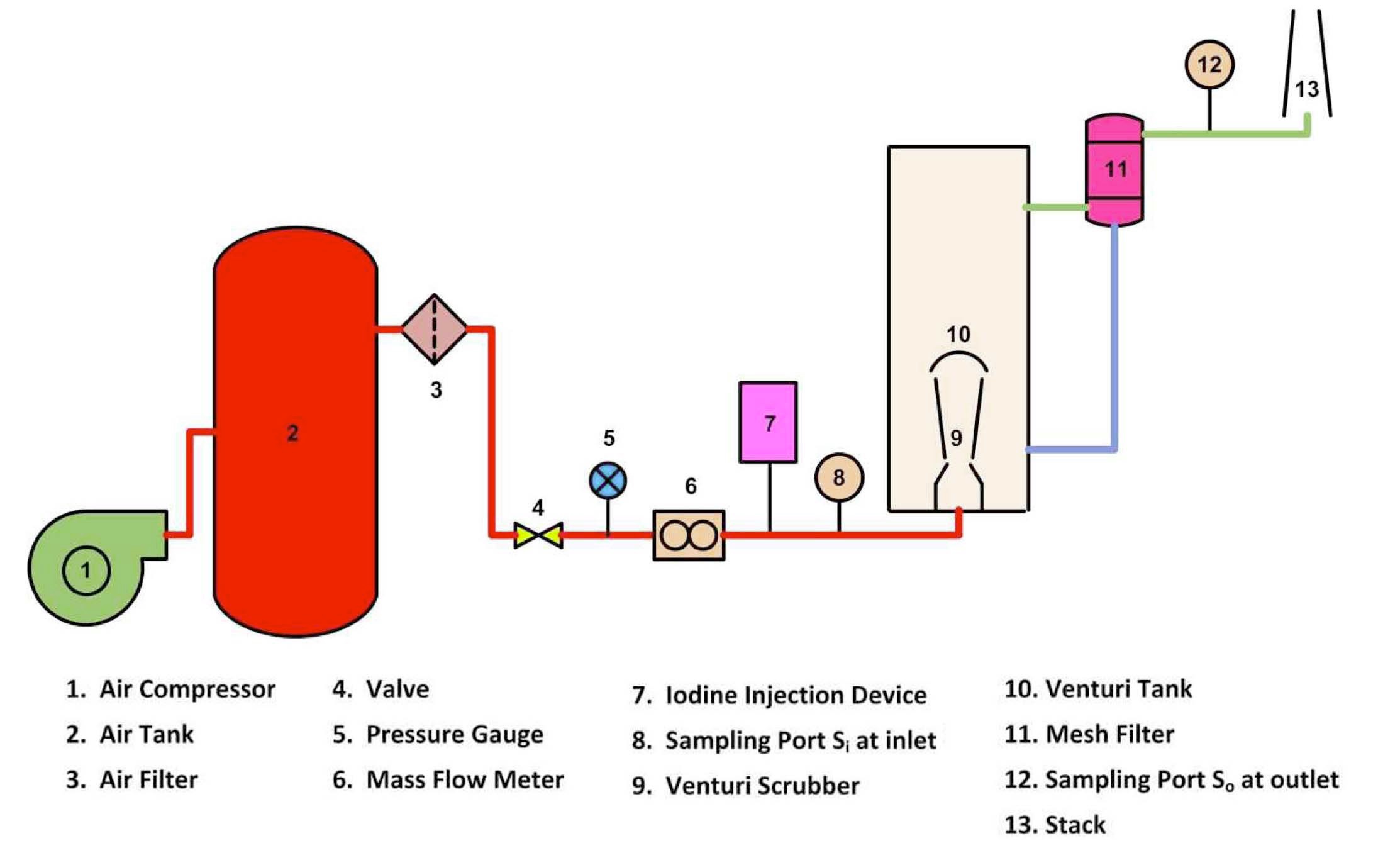
The schematic diagram of the experimental facility to study the iodine removal efficiency in a self-priming venturi scrubber is shown in Figure 3. The compressed gas from an air compressor is stored in an air tank. The gas is airfiltered. The gas flow rate is adjusted by a valve. The mass flow rate of gas is measured by a mass flow meter. The direction of gas flow in a venturi scrubber is against gravity. The aqueous solution is prepared by adding 0.5% (w/w) sodium hydroxide (NaOH) and 0.2% (w/w) sodium thiosulphate (Na2S2O3) in water. The venturi tank is filled with aqueous solution and is positioned at a certain height to create the requisite hydrostatic head effect. A constant liquid level in a venturi tank is maintained for each run. The liquid introduced into the scrubber is in the form of film. The leaving liquid at the outlet of a venturi scrubber is collected in the venturi tank and is recycled. In iodine injection devices, the iodine is kept in a constant temperature chamber and iodine gas is generated through a sublimation process. The sample of iodine gas is collected at sampling point Si (inlet concentration) and So (outlet concentration). The concentration of iodine in the sample is measured by using a spectrophotometer. The mesh filter is installed at the downstream of a venturi tank to remove
the droplets from gas. When iodine gas I2 reacts with NaOH and Na2S2O3, the following reaction takes place:
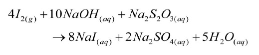
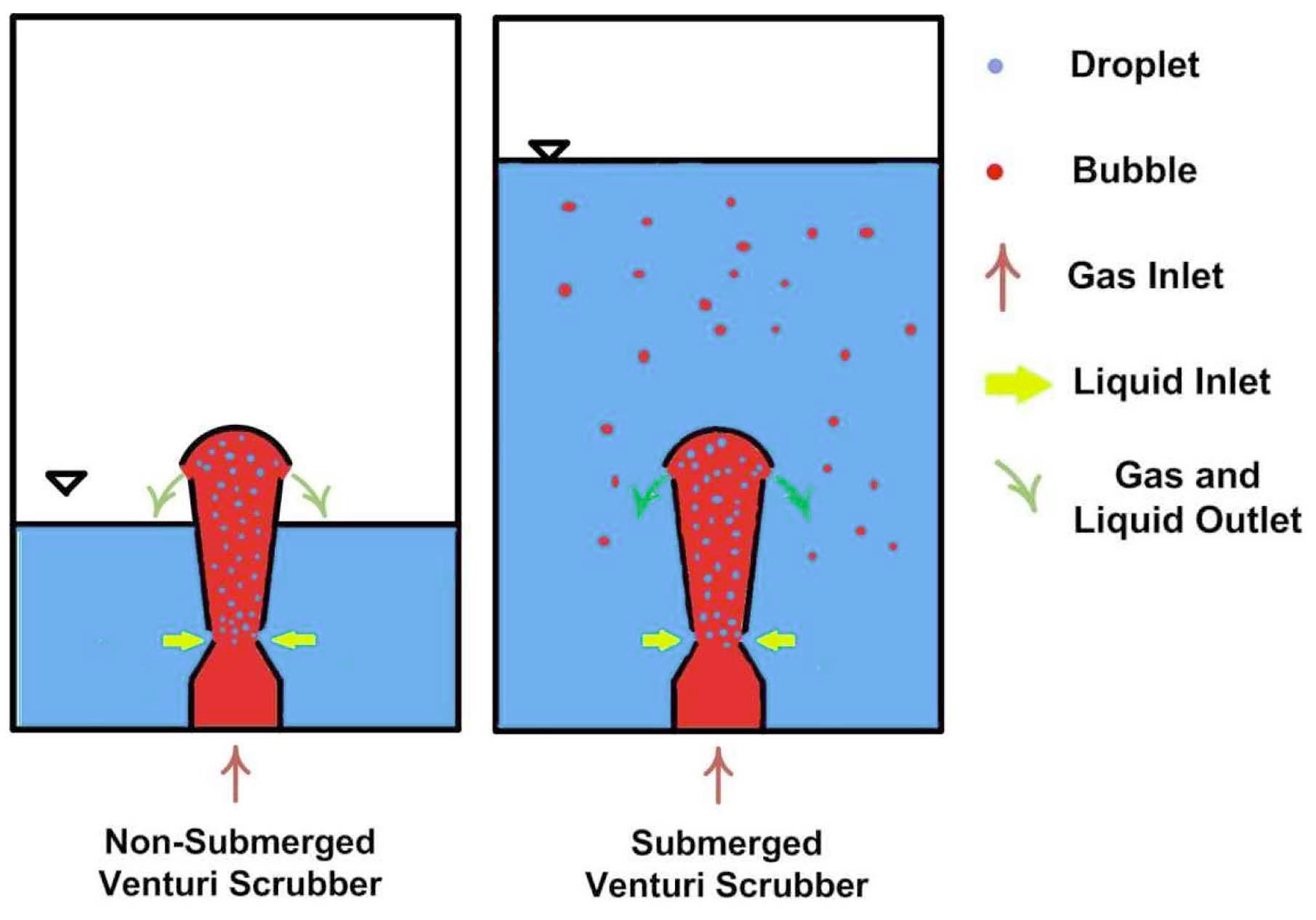
A self-priming venturi scrubber is operated at two different operating conditions: a non-submerged venturi scrubber, and a submerged venturi scrubber. The working of a non-submerged and a submerged venturi scrubber is presented in Figure 4. In a non-submerged condition, the venturi scrubber is not immersed in the venturi tank whereas in a submerged condition, the venturi scrubber is immersed in water. The liquid flow rate depends on the hydrostatic head of the venturi tank. If the level of water is higher in a venturi tank, the flow rate of liquid into a venturi scrubber is higher. The leaving water from the outlet is collected in venturi tank and is recirculated-submerged venturi scrubber, only droplets take part in iodine removal efficiency. However, in a submerged venturi scrubber, droplets and bubbles take part in iodine removal efficiency because at the outlet of a venturi scrubber, the droplets are collected in water above it but gas will escape in the form of bubbles.
The absorption process is defined as the transfer of a gaseous component from the gas phase to a liquid phase. According to the two film theory, the mass transfer phenomenon has taken place at the gas liquid interface due to the concentration differences between gas and liquid phases [15]. The absorption process continues as long as
the concentration difference exists between liquid and gas phase. The absorption process can be enhanced by increasing the contact time between phases, greater interfacial contact area between phases, and by increasing the turbulence or good mixing of the phases [11].
In this research work, the iodine removal efficiency in a self-priming venturi scrubber is analyzed. The iodine removal efficiency is operated at different gas and liquid volumetric flow rates. The concentration of NaOH and Na2S2O3 in scrubbing water remains the same. According to the definition of a self-priming venturi scrubber, the injected liquid depends upon the pressure difference between the hydrostatic pressure of the liquid in the tank and the static pressure of the gas in a venturi scrubber [7]. If we increase the hydrostatic head in the tank, the volumetric flow rate of liquid increases. The liquid is injected into the throat section in the form of film. According to Bernoulli’s principle, the high gas velocity in a throat causes suction of liquid due to low pressure. The high gas kinetic energy scrubbed the aqueous solution into petite droplets. In the throat section, these tiny droplets accelerate while decelerating in the diffuser section.
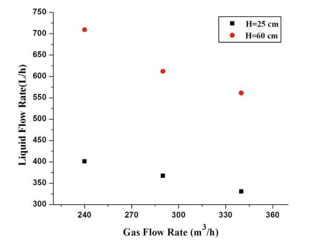
Lehner [7] categorized the venturi scrubber into two types based upon the liquid supplied: forced feed, and self-priming. In the force feed method, the liquid is supplied through pumps so that liquid flow rate is independent of the gas flow rate. But, in a self-priming venturi scrubber, the liquid flow rate depends upon the gas flow rate. The liquid supplied into a self-priming venturi scrubber depends on the static pressure of gas at the throat and hydrostatic pressure of the liquid in the want tank. The liquid flow rate is analyzed at different gas flow rates. Figure 5 depicts that with the increase of throat gas velocity liquid flow rate decreases. It is also observed that the increase of the hydrostatic head in the tank increases the flow rate of liquid.
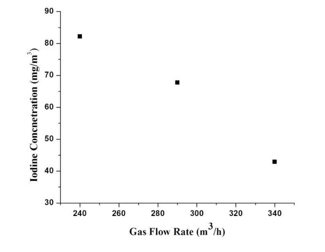
4.2 Effect on Concentration due to Gas Flow Rate
Figure 6 depicts the relation between the gas flow rate and concentration. It the mass flow rate of injected iodine into the loop is fixed, the concentration of iodine is decreased in the venturi scrubber with the increase of gas flow rate.
4.3 Comparison between Non-Submerged and Submerged Venturi Scrubber
Iodine removal efficiency is investigated at nonsubmerged and submerged conditions with the single-unit venturi scrubber in a venturi tank which is as follow:
4.3.1 Non-Submerged Venturi Scrubber
In this case, the venturi tank is filled with water in such a way so that the venturi scrubber is not submerged in it. The volumetric flow rate is adjusted by adjusting the height above the liquid in the venturi tank. The liquid flow rate is less, as compared to the submerged venturi scrubber. The iodine gas is absorbed in droplets, which are formed in a venturi scrubber.
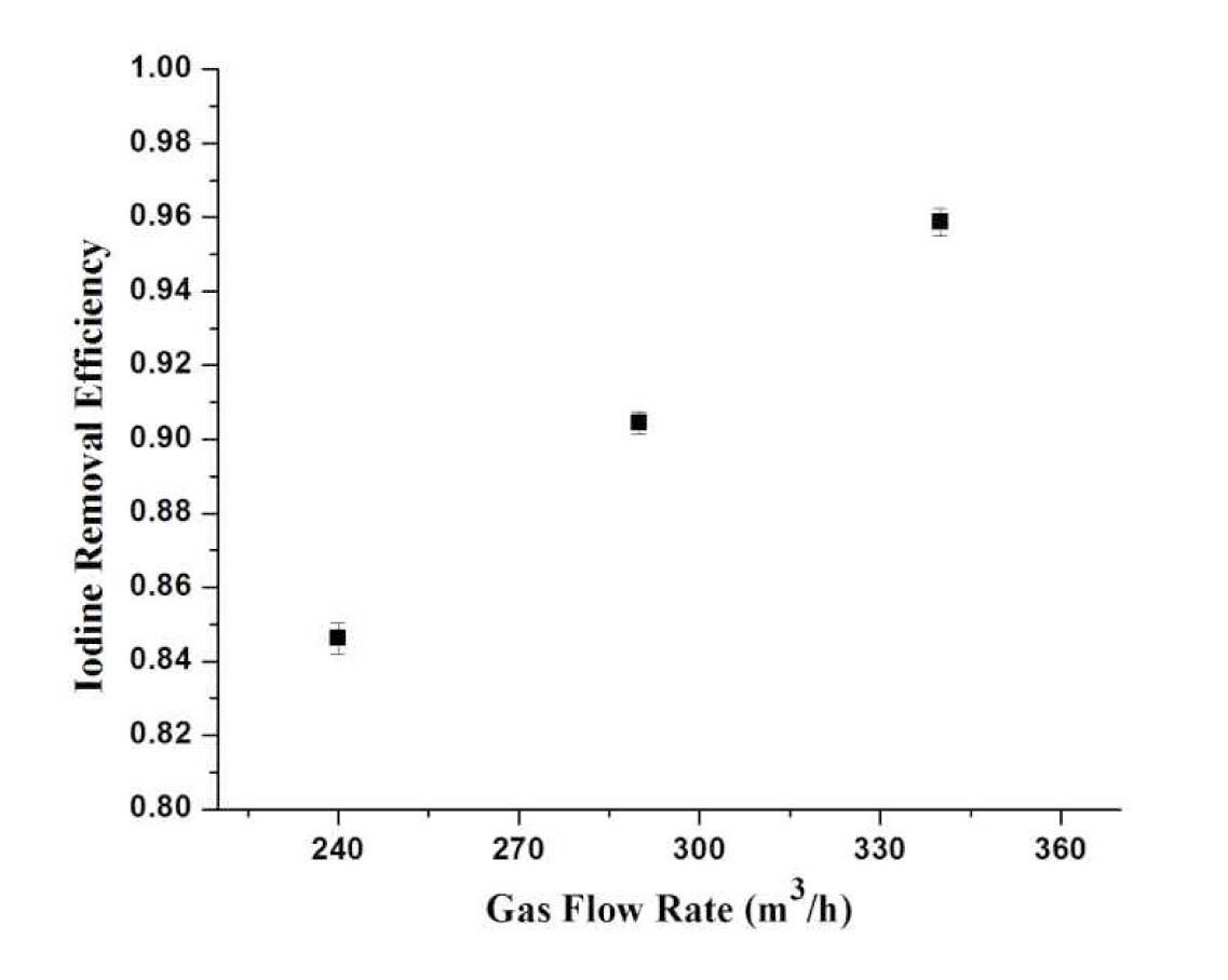
4.3.1.1 Effect of Gas Flow Rate
Figure 7 depicts the relationship between the iodine removal efficiency at different gas flow rates. It is observed that with the increase of the flow rate of gas, the iodine removal efficiency also increases. At higher gas flow rates, the kinetic energy of gas is higher which disintegrates the liquid into tiny droplets and increases the number of droplets. As a result, the interfacial area of droplets increases which causes the increase of mass transfer of iodine into droplets.
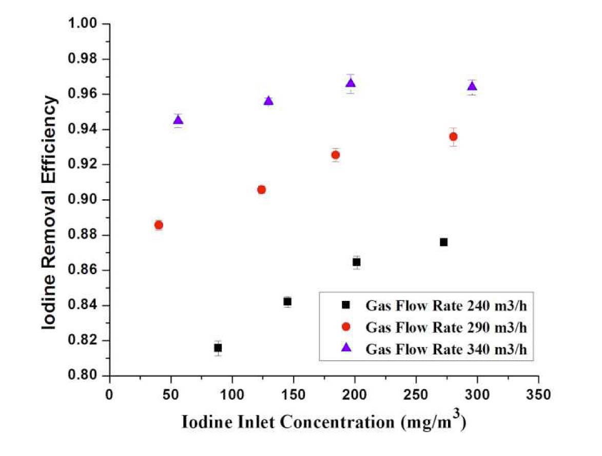
4.3.1.2 Effect of Inlet Concentration
Figure 8 gives the results of iodine removal efficiency at various gas flow rates for different inlet concentrations of I2. The inlet concentration of I2 varies from 40 to 300
(mg/m3). The graph shows the increase in iodine removal efficiency with an increase of Cin at same gas flow rate. On the other hand, the iodine removal efficiency is increased by an increase of flow rate.
4.3.2 Submerged Venturi Scrubber
In this case, the venturi tank is filled with water in such a way that the venturi scrubber is submerged in it. The volumetric flow rate is adjusted by adjusting the height of the liquid above the venturi scrubber in a venturi tank. The iodine gas has two chances to contact with the aqueous solution. The high kinetic energy of the gas disintegrates the liquid into droplets in the throat section. When the gas departs from the venturi scrubber, it passes through the water bed in the form of bubbles. Therefore, the gas interacts with the droplets first in the venturi scrubber and then interacts with the liquid in the form of bubbles through the water bed above the venturi scrubber.
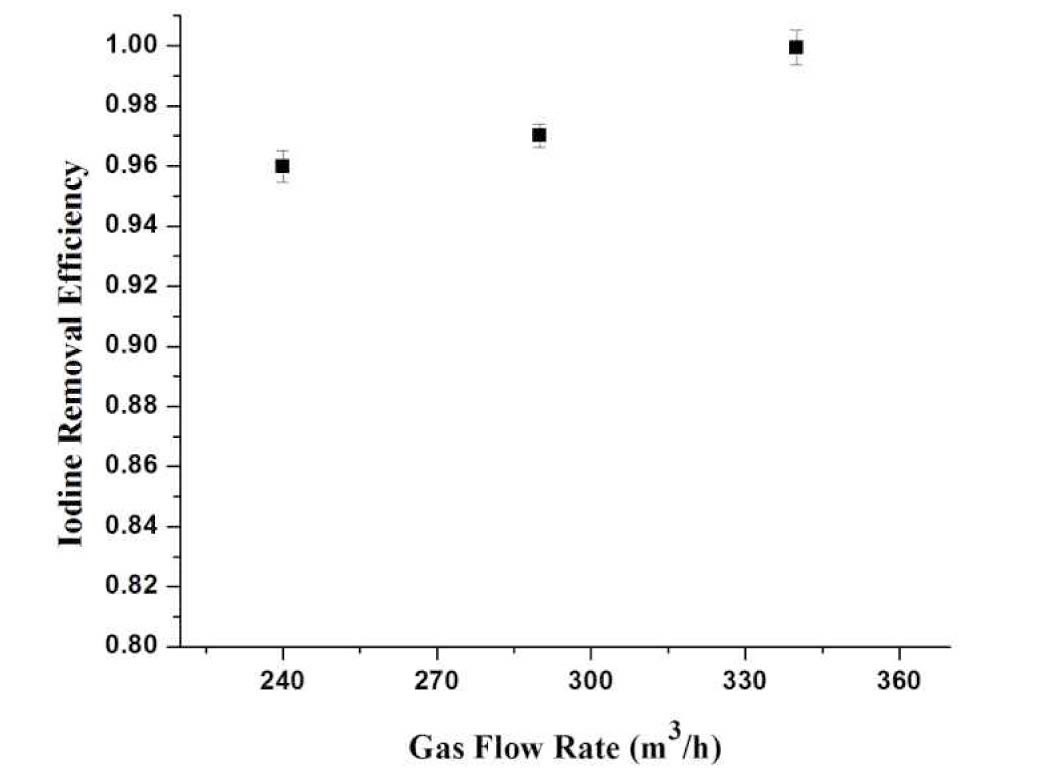
4.3.2.1 Effect of Gas Flow Rate
Figure 9 illustrates the relationship between the iodine removal efficiency at different flow rates. It is observed that the iodine removal efficiency increases with the increase of gas flow rate, and it is higher than 0.995. The highest iodine removal efficiency of 0.999±0.001 is achieved. The removal efficiencies are higher as compare to a non-submerged venturi scrubber due to two reasons: firstly, increase of flow rate of liquid and secondly, interaction of gas in the form of bubbles with the surrounding liquid when passing through the water bed.
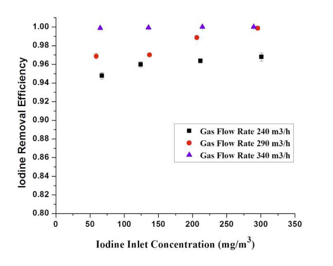
4.3.2.2 Effect of Inlet Concentration
Figure 10 provides the results of iodine removal efficiency at various gas flow rates for different inlet concentrations of I2. With the increase of iodine inlet concentration at the same gas flow rate, the iodine removal efficiencies are almost similar. It is due to the gas rises from the water bed in the form of bubbles. The iodine removal efficiencies increase with increasing gas flow rate.
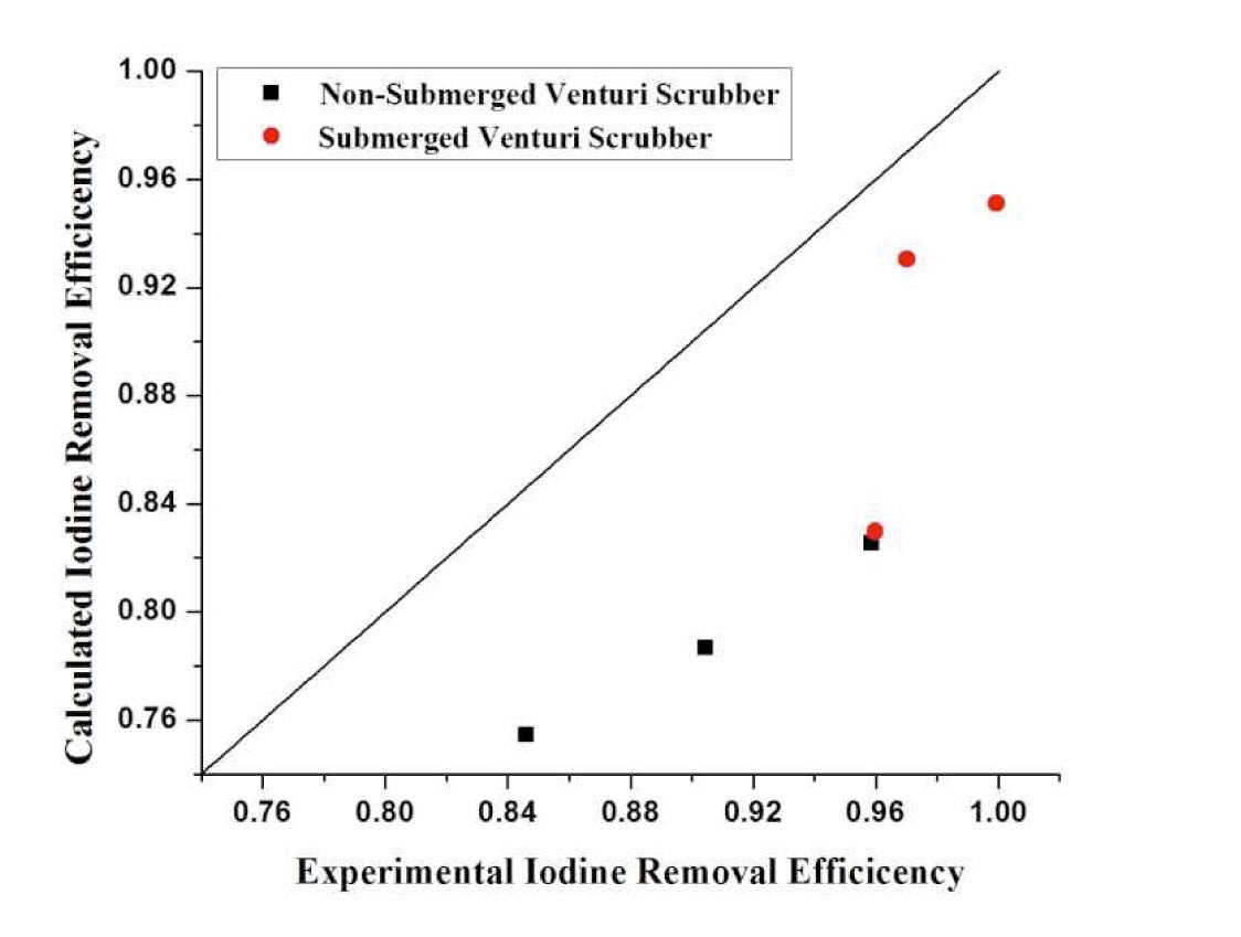
Figure 11 shows that the theoretical model for a nonsubmerged venturi scrubber underpredicts the results, but the results obtained from the submerged venturi scrubber explain and satisfy the results well. The results were underpredicted because no liquid film on the walls had been supposed. As the Gamisans, the results indicate a considerable improvement in the predictions when the scrubbing effect of the liquid film travelling along the venturi tube walls is considered. Another reason is the partition coefficient effect, which is not considered in the model.
In this research, the iodine removal efficiency in a self-priming venturi scrubber is investigated. Liquid introduced into the scrubber is in the form of film. The aqueous solution is prepared by adding 0.5% sodium hydroxide (NaOH) and 0.2% sodium thiosulphate (Na2S2O3) in liquid. A self-priming venturi scrubber is operated with a non-submerged venturi scrubber and a submerged venturi scrubber. The following results are concluded from the present work;
1. The iodine removal efficiency of a venturi scrubber increases with the increase of gas flow rate and iodine inlet concentration.
2. A submerged venturi scrubber has higher iodine removal efficiency than the non-submerged venturi scrubber.
3. The highest iodine removal efficiency of 0.999 ±0.001 is attained in the submerged venturi scrubber.
4. The results from a theoretical model based on mass transfer concur well with the submerged venturi scrubber experimental results but underpredicts with non-submerged venturi scrubber.
C concentration (mg m-3)
C' concentration in water bed above venturi scrubber (mg m-3)
r radius (m)
t time (s)
k mass transfer coefficient (m-1)
V Volume (m3)
v velocity (m s-1)
Sh Sherwood number (dimensionless)
Re Reynolds number (dimensionless)
Sc Schmidt number (dimensionless)
d diameter (m)
D diffusion coefficient (m2 s-1)
ρ density (kg m-3)
σ surface tension(N m-1)
Q volumetric flow rate (m3 h-1)
μ viscosity (Ns m-2)
V' geometry volume (m3)
E efficiency
l length of water bed in venturi tank above the venturi scrubber (m)
N rate of absorption into droplet (kmol s-1)
Subscript
d droplet
b bubble
r relative
l liquid
g gas
re removal efficiency
in inlet
out outlet
T throat
D diffuser
m distribution parameter
i interface
I iodine

![AREVA Filtered Vented Containment System [5]](http://oak.go.kr/repository/journal/12373/OJRHBJ_2013_v45n2_203_f001.jpg)
![Difference between Force Feed Mode and Self-Primng Mode Venturi Scrubber [7]](http://oak.go.kr/repository/journal/12373/OJRHBJ_2013_v45n2_203_f002.jpg)