LED lighting control system using unidirectional DMX512 (digital multiplex with 512 pieces of information)) protocol has been the most popular. Nowadays, the user’s consumption has been upgrading to the more intelligent system but the upgrading process does not affect the existing infrastructure. There were many researches use the additional communication for the feedback communication way such as WiFi, Controller Area Network (CAN), Power Line Communication (PLC), etc but all researches had inherent disadvantages that created the independent feedback with the existing DMX512 system. Our paper represents the novel method that uses the remote device management (RDM) protocol to associate the additional feedback with existent DMX512 infrastructure in the one system. The data in DMX512 frame sending to the DMX512 client is split and repacked to become the RDM packet. This RDM packet is transferred to the RDM monitor console and the response RDM packet is converted to the DMX512 frame for control DMX512 client devices. This is the closed loop control model which uses the bidirectional convertibility between RDM packet and DMX512 frame. The proposed method not only upgrades the feedback control function for the old DMX512 system without changing the existent infrastructure, but also solves compatible problems between new RDM devices and old DMX512 devices and gives the low cost solution for extending DMX512 universe.
The light is one of the most important elements of life and lighting technologies using LED have become our present and near future. DMX512 (digital multiplex with 512 pieces of information) was the preferable control protocol for LED lighting control. However, over the years, the user’s consumptions have been trending to be more intelligent and efficient system [1,2]. These systems have been identified as critical research areas by the US Department of Energy which uses the bidirectional protocol with the feedback control loop. DMX512 is only the unidirectional protocol. Hence, there were many researches that use the additional media communication for the feedback control such as WiFi, Controller Area Network (CAN), Power Line Communication (PLC) or etc to improve the DMX512 system. Our research gives a novel method using remote device management (RDM) protocol without affecting the DMX512 system. RDM is a protocol developed by Entertainment Services and Technology Association Technical Standards. RDM is the protocol enhancement to DMX512 that allows bi-directional communication between a lighting system controller and attached RDM compliant devices over a standard DMX512 line. Nowadays, more and more devices have been supporting RDM protocol.
The upgraded process arise problems about the compatibility because there are both DMX512 devices and RDM devices in the one system, namely, DMX512 devices cannot control RDM devices and RDM devices also cannot control DMX512 devices. Therefore, the system needs the solution that makes the compatibility between two kinds of different equipments. This paper is a novel principle that focuses on discovering and applying new methods of control and feedback in the DMX512 network. The methodology is based on bidirectional converter between RDM packet and DMX512 packet, the research designs devices that make the RDM devices and DMX512 devices to work together in the one system. Moreover, we have an additional solution to extend the DMX512 universe. This solution is a lower cost and simpler than others. It is suite for small number of the universe. Furthermore, this research also makes the new way to improve the existent DMX512 network without changing the infrastructure.
2. LED Lighting Control System
2.1 LED Lighting Control Protocols
A lighting control system consists of devices that controls electrical lighting and devices, alone or as a part of a daylight harvesting system, for a public, commercial, or residential building or property, or a theater. In fact, most of LED lighting system consists of many lighting hence the system needs a protocol to connect elements to become the network. There are a lot of the connecting protocols for LED lighting control system [4].
KNX is a standardized, open source initiative (OSI)-based network communications protocol for intelligent buildings and lighting control is the basic function. The KNX system is built up by technically complex system parts which can be quite expensive. In most cases, special software is required which increases the installation cost. LonMark/LonWorks is a general purpose network using the LonWorks protocol and the Neuron chip but this protocol is not popular because it is the proprietary and hardware is specific. BACnet is a data communication protocol for building automation and control networks for applications such as heating, ventilating air-conditioning control, lighting control and their associated equipment. The system is technically advanced and the need for specific knowledge by the installer as well as specialized software is needed. ZigBee
is a wireless network standard, based on IEEE 802.15.4 physical layer (PHY) and medium access control (MAC) sublayer. The ZigBee network technology is based on the seven layer OSI model. Zigbee or any wireless protocol is not always more robust than the wired. Digital Addressable Lighting Interface (DALI) is a digital communication protocol designed specifically for lighting systems. DALI defines the system’s maximum size as 64 single units (individual ad-dresses), 16 groups (group addresses) and the topology of the system can be bus, star or a combination of these two, but a ring topology is to be avoided. Power line carrier is a system for carrying data on a conductor that is also used for electric power transmission. The distance, speed and interference in the power line communication technology have been developing.
Furthermore, DMX512 and RDM are two protocols which are the most popular and dedicated for LED lighting control.
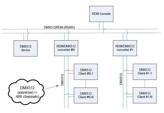
The DMX512 standard, henceforward simply called DMX512 or DMX, describes a data stream protocol over a balanced cable pair. The data is sent from the master or a transmitter to the slave or receiver. There can be multiple slaves, but only one master. One DMX master can send up to 512 channels of data. The combination of these channels is known as a frame. The DMX bus that connects the master to all slaves is called a universe. When more than 512 channels of data are needed, additional universes (physical DMX ports) are needed. The channel numbers continue to add up further with each new universe namely, universe 1 is from channels #1 to 512, universe 2 is from channels #513 to 1024, etc.
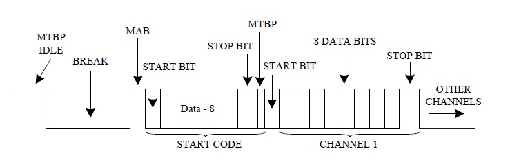
The timing diagram at the Figure 1 shows that the bus is always in one of these states. Idle state is no communication, the bus will be high. Break state is DMX frames beginning with a negative transition of the bus after which the bus must stay low for 88
would recognize the frame. Mark After Break (MAB) state follows immediately the break signal. It is a high signal with the duration of 2 bits. The start code and each of the channels are 11 pulses wide including one start bit and 2 stop bits. The information itself are 513 bytes, the first one being the start code, the next 512 bytes represent the DMX channels: one low bit (the start bit); eight bits of data, representing a number between 0 and 255; two high stop bits. In a normal DMX system, the start code data is all zeroes. The Mark Time Between Frames (MTBF) is the idle time with a high signal between channels. This pause is not required, but it is allowed to last as long as one second.
RDM (Remote Device Management) is a protocol enhancement to United States Institute for Theatre Technology (USITT) DMX512 that allows bi-directional communication between lighting with a system controller and attached RDM compliant devices over a standard DMX line. This protocol will allow configuration, status monitoring, and management of these devices in such a way that does not disturb the normal operation of standard DMX devices that do not recognize the RDM protocol.
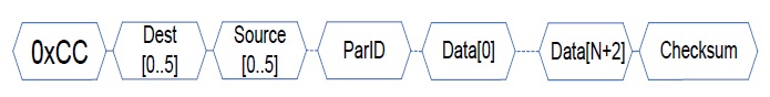
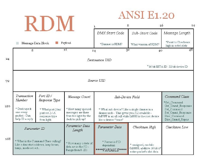
The Figure 2 shows that the Start code is 0xCC and Sub start code field (1 byte) is 0x01. Message length field (1 byte) is the length of the RDM packet. Destination UID field (6 bytes) is the destination address. Source UID field (6 bytes) is the source address. Transaction number field (1 byte) is the number

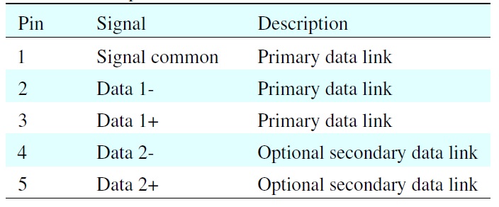
XLR-5 pinout
of the transaction. Port ID/response type (1 byte) is the index of the device’s port or the type of response packet which is ACK, response packet, etc. Message count filed (1 byte) is the index of the message in the session. Sub-device field (1 byte) is the description of the device in group. Message data block field is the data field. Check sum (2 bytes) is the check sum of the RDM packet. RDM communication can be broken down into three types: discovery; uni-cast communication; broadcast communication.
We analyze similar and different points to find the convertible method. The first similarity is timing and this is one of the most important features of protocols. The DMX and RDM transmit data over the bus at 250 kbit/sec. Therefore, every bit is 4
Similarities are about connector, electrical, cable and both protocols use types of the connector. The XLR-5 connector in the Table 1 is more popular than RJ11 or XLR-3 connector. The electricity is EIA-485 voltage. These similarities make RDM and DMX512 to work together.
There are many differences between RDM and DMX.We list them in the Table 2. The difference about the start code makes RDM devices and DMX devices can to interfere between them without collisions. DMX devices ignore the frame which has the distinctive start code with 0x00 and RDM devices also ignore packets which have the distinctive start code with 0xCC. The bidirectional feature of RDM protocol is a improvement with unidirectional DMX so new functions such as status monitoring, automatic device discovery are only in RDM.
3. Bi-directional RDM-DMX Converter
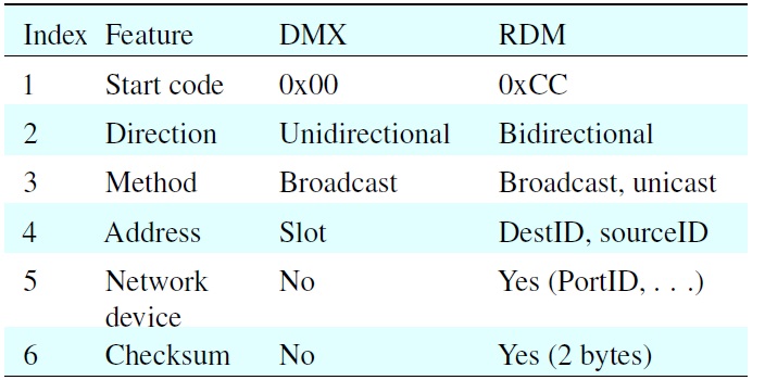
RDM vs. DMX512
3.1 Bi-directional Convertible Mechanism
When users upgrade the DMX system, there are many challenges. The upgraded system needs the bi-directional communication which has the closed feedback control loop but this upgraded system does not affect the existing DMX512. Moreover, when we upgrade the system DMX512 to the RDM, there are two types of the independent devices in one system. The asynchronous system is not good actuator. Hence, we propose the convertible method between RDM packet and DMX512 frame. If the convertible process is the RDM to DMX512, it receives the RDM packet input, splits the data filed, repacks and transmits DMX512 frame output. If the convertible process is the DMX512 to RDM converter function, it receives the DXM512 frame input, splits the data from the slot, repacks and transmits RDM packet output. The address of the converter can be set by a hard switch or firmware.
The media communication of the RDM protocol is broadcast and unicast. If the convertible device is the RDM to DMX, it has the RDM address for the communication with other RDM devices in the system.
The RDM address includes 6 bytes for destination address and 6 bytes for source address. When the converter receives
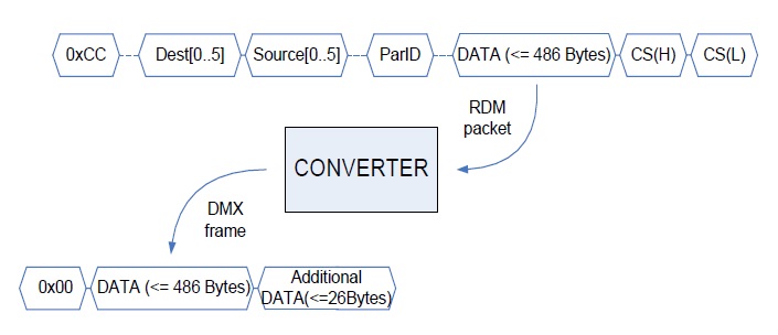
the RDM packet, the converter checks the type of packet. If the type of packet is specification such as Discovery, Identify, Ack, etc the converter will reply by Respond DISCOVEY() or Respond msg(). The Discovery packet is the broadcast packet and its destination address is 0xFFFFFFFFFFFF. Identify, Ack, the others specific packet has the specific value of the CmdCls and ParID field. The other type of RDM packet is converted to DMX frame as shown in Figure 3. The RDM data field is split, repacked by DMX frame. However, the maximum number of channel in the DMX universe were 512 channels but in the RDM, 24 bytes were for the header and 2 last bytes were for check sum so maximum number of DMX byte contained in RDM data field which are 486 data bytes. Hence, we address DMX slots from 1 to 486. We can change the DMX512 address but the number of address must be less than 468. The Figure 4 demonstrates visually the process. The additional data is optional.
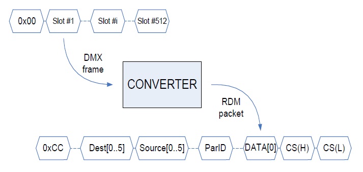
If the convertible device is the DMX to RDM, the converter works as DMX512 client and it also uses the DMX512 address to receive the data. This address is set by a hard switch or a firmware. The DMX512 data is split from the slot that is corresponsive with the setting address, repack by RDM packet to send to the RDM destination device. The Figure 4 shows visually the method. RDM is the bi-directional protocol and it uses the method that is a session communication with reply packet.
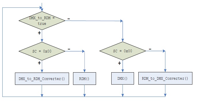
We propose the algorithm to implement the converter. The general flowchart is showed in the Figure 5. Packets on the network are captured by the converter. The structure of the packet is analyzed and converted by the above principles. This function is selected by the hard switch or the firmware. The converter works as the RDM device or DMX device hence, we can keep the existing infrastructure.
If the function of the device is DMX_to_RDM and the start code is 0x00, DMX_to_RDM_converter() function implements the convertible process for packet from DMX to RDM (Figure 6):
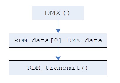
DMX() function is the DMX transceiver (Figure 7). Received DMX data by DMX() assigns to the first RDM data byte. RDM_transmit() function transmits RDM packet to the network.
If the function of the device is not DMX to RDM and the start code is 0x00, RDM_to_DMX_converter() function is called to convert from the RDM packet to DMX frame (Figure 8).
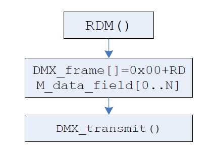
RDM() function is the RDM transceiver (Figure 9). Received RDM data by RDM() assigns to the DMX frame by adding start code 0x00. DMX_transmit() function transmits DMX frame to the network.
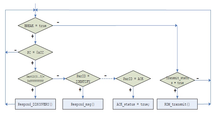
In this function, type of packet is detected by Destination ID (DestID) or parameter ID (ParID). If DestID = 0xFFFFFFFFFF, the packet is discovery packet and the RDM() responds by Respond DISCOVERY() function but if the packet is IDENTYFY or the others, the RDM() is responded by Respond_msg() function that has a ACK packet so there is the problem that is the RDM information output is slower than DMX information input. The proposed solution uses the FIFO buffer for DMX
frame input to solve this problem.
Although the DMX LED lighting control devices are available as popular and commercial products, almost current systems only provide actuation and do not exploit feedback control using monitor by the sensor data. We believe that it is important and the upgraded DMX system needs the other media communication for the feedback monitor. There are many researches used the media communication as WiFi [5], PLC [6], CAN [7] or etc but it is not perfect. WiFi technology have disadvantages about the power supply, distance, noise. PLC technology have disadvantages with the short circuit, noise, distance. The others need the additional infrastructure for communication. This is not feasible in the practical. Moreover, all of them make the independent feedback communication with DMX system and cannot become the intelligent closed loop control, namely, the light at the area usually is created by many sources or DMX
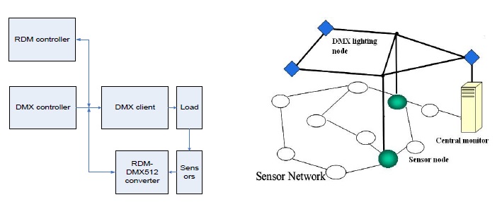
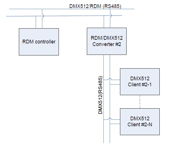
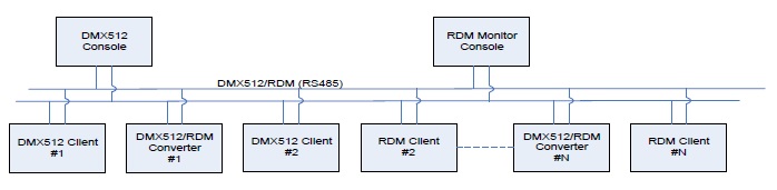
clients. The sensor data only shows the change of the light without detecting which is a changeable source. The proposed converter can upgrade the monitor function to create the intelligent closed loop control system for DMX512 system without changing infrastructure (Figure 10).
This application also can be useful for many illumination purposes, such as indoor office, home and museum lighting or outdoor lighting for a stadium and advertisements with multi purposes such as energy saving, art color render. The closed loop control system is monitor system which has the general model.
The data from sensors are collected and data in DMX512 frame transmitting from DMX512 controller to DMX512 client also are received by RDM-DMX512 converter. All of the data are repacked to RDM packet and sent to the RDM monitor console. RDM monitor console can control DMX512 client by inserted DMX512 frame. We propose the structure of the packet as follow (Figure 11):
The data field includes N+3 byte for: 2 Bytes for the DMX512 client address, 1 Byte for the data of the DMX512 client, N Bytes for the collected data from the sensor. The number of data byte depends on every application, sensor and our application is 8 Bytes. This is one of the most different points of the paper
because it can collect the data from every client DMX512 frame and the data from the sensors to support the closed loop control.
Hence, we combined the DMX to RDM method and the collected sensor data to monitor the old DMX system without changing existent infrastructure.
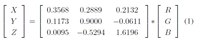
In the LED lighting control applications [8], we also propose the method using light sensor to collect vital parameters of the light as color temperature, intensity. The X, Y, and Z tristimulus values characterize color and they are linear-light quantities, proportional to optical power, that incorporate the wavelength sensitivity of human vision but the almost light sensor only gives R-G-B values so we compute the value X-Y-Z in the color space from the RGB information by the following equation:
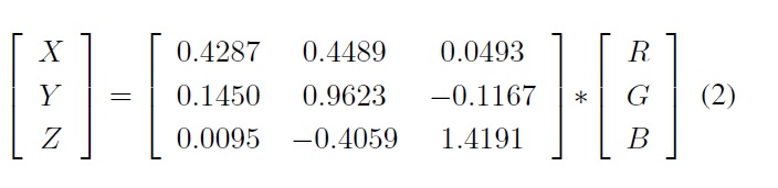
The optimum transform for the ColorChecker illuminated by CIE D65 is determined to be this:
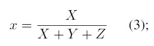
And then, we compute the x, y values for the Color Temperature by equation:
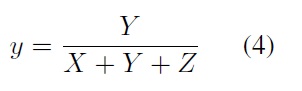
And then, based on the graph we can calculate the color value [9].
McCamy’s formula [10] can be used to determine the correlated color temperature (CCT) from the chromaticity coordinates.

where
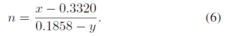
CCT is basically a description of whether the light is bluishwhite, neutral, or reddish white.
The frequency sent to us by the chip correlates to a particular amount of radiant energy being received by it. We need to convert it to a more useful representation, and the target is a measurement of micro-watts (uW) per centimeter squared (cm2).
This application can solve many practical problems. For example, when a zone contains more than one workplane, lighting from Illumination Fields may overlap and influence other workplanes. Consider the simple scenario for a zone which have two workplanes. The first workplane requires 500 lux and the second workplane requires 350 lux. When the first workplane turns on, the sensor at the second workplane detects 88 lux, so we need to provide 262 lux for the second workplane to archive 350 lux but this spill over to the first workplane becoming 550 lux. Therefore, we will compute value until the required levels are reached for both workplanes using small increasing steps.
3.3 Crossover Control and Extending
In fact, almost user can not upgrade all DMX512 devices in one time. Hence, there are usually both DMX512 and RDM devices in the network. Although DMX512 devices have no collision with RDM devices, they cannot transfer the information together, for instance, DMX512 devices cannot control or receive the command with RDM devices. RDM devices also cannot control or receive DMX512 frame. So, there are two sub-systems in the one infrastructure. Now there is no solution to solve this problem but the proposed converter can do this. The DMX512 console device transmits DMX512 frames to the converter. The converter splits and converts this DMX512 frame to RDM packet and transmits it to the RDM client device. Hence, DMX512 console can control the RDM client via the converter (Figure 12).
Similarly, the RDM console device transmits RDM packet
to the converter. The converter converts the RDM packet to DMX512 frame and retransfers to the network. All devices in the system become compatibly together. In this application, we combined RDM to DMX and DMX to RDM function in one device.
Over the years the requirements about number of devices in DMX512 system grew up more than 512. There are two solutions to solve this. The first solution uses the multi-universe DMX512 console devices such as Chamsys MagicQ MQ200 pro up to 32 universes, stand 200 plus or etc. The second solution is DMX512 with other high speed protocols such as Artnet, CAN, etc. The console device uses the high speed stream such as WiFi, Ethernet, etc which includes many low speed DMX512 stream inside. The converter gives additional solution to solve the problem. If we separate the RDM input and DMX512 output of the converter, we can extend the number of the DMX512 universe. RDM console device send the RDM packet which includes DMX512 data inside to the converter. The converter transfers DMX512 frames to the other universe. Compared with the other solution, this solution is simpler, lower cost than others. It can accommodate applications that have few DMX universes. We apply RDM to DMX method but we separated the RDM input and the DMX output (Figure 13).
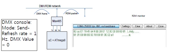
To test this experiment, we use the model (Figure 14).
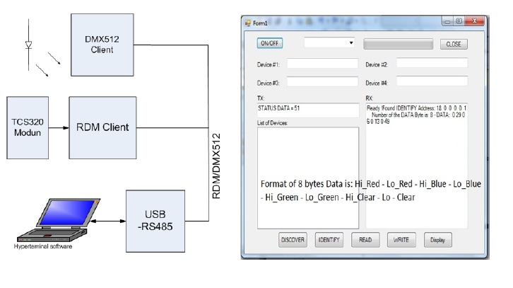
DMX console is DMX transmitter with the 0 value (other value is OK) which transmits a DMX frame to the converter. In the paper, we use the open source DMX console for the standard
test. The RDM monitor is the terminal software to display the RDM packet on the screen of the PC. We can see bytes of RDM packet: Start code of packet (SC) is 0xCC, address of the destination device (DestID) is 0x194164FF0000 and address of the source device (SourID) is 0x011200000000, etc, DMX data value is 0x00, two bytes for check sum are 0x02E1. It means that the DMX data converts to the RDM packet by the converter.
RDM transmitter is the above converter or Open RDM software which transmits the standard RDM packet to the uC module. uC module receives the RDM packet, splits the data field and repacks to become the DMX512 frame. We can look at the right side of the figure to see that the DMX data which is inside the RDM data field showed by DMX monitor (Figure 15).
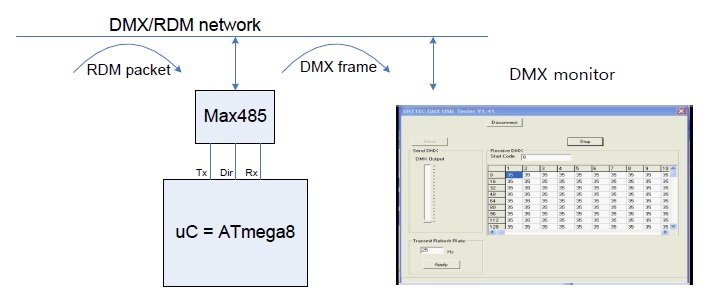
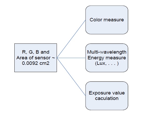
In this application we use the light sensor that is TCS3200D to measure vital parameters of light (Figure 16).
The datasheet of TCS3200D [11] shows us a graph of the spectral responsiveness. The graph shows us that at a wavelength of 640nm, and 1x sensitivity and the relationship between uW/cm2 and the frequency is a ratio of 1:10. The energy is 1/10th the frequency-uW/cm2 = Freq/10. An important point is that the actual sensor has an area of about 0.0092 cm2.
The testing modules are TCS3200 sensor and microcontroller. The light source is seven 5mm red LEDs and the distance is about 2.5 cm (Figure 17).
The result shows that the experiment can receive the data from the light sensor and send it to the RDM monitor by RDM packet. The frequency of red-blue-green is 290 cd*m2 - 60 cd*m2 - 130 cd*m2 because the sample duration is 0.1s. We calculate XYZ by the Eq. (2), [X Y Z] = [151.897984.617162.884]. And we have x and y values by Eq. (3) and Eq. (4), x = 0.380316; y = 0.021186. By using the Chromaticity Diagram with Planckian Locus [9], we can see the color of the light source is the red. By applying to Eq. (5) and Eq. (6), we can calculate the CCT of the light source is that n = - 1855, CCT~1198 K.
In this model, the power of LED module is controlled by DMX512 client and light parameters as R-G-B frequencies are measured by the light sensor - TCS3200D. Parameters are sent to the RDM monitor console by the RDM packets. We can add or remove the additional monitor system without effect to DMX512 devices.
4.4 Experiment 4: Crossover Control
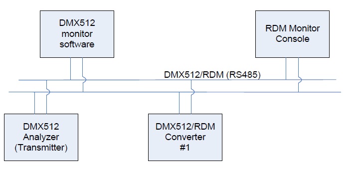
We use the experimental network model with 4 elements to test the experimental cross control (Figure 18). If there are more than 4 elements, the system works well but the result is observed difficultly.
In this model, DMX512 analyzer (transceiver): open DMX512 hardware which transmits DMX512 data to the network.
DMX512 monitor is the open source client software with USB dongle. This software shows the received DMX512 data on the screen of the PC.
RDM monitor console is the proposed software to display the received RDM data on the screen.
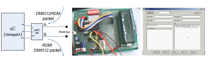
RDM-DMX512 converter is the proposed hardware (Figure 19).
The result shows that the DMX512 data is converted to the RDM packet by the converter and the data field of the RDM packet is converted to the DMX frame. It receives the DMX512 data from slot 11 (data = 131) to convert the DMX512 data to RDM packet and sends the RDM packet to network. The converter works as the transponder with one port for RDM packets and DMX frames.
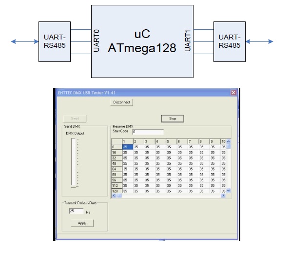
We also use the model with four elements to test the experiment about the DMX512 universe extension (Figure 20).
We use Atmega128 because the microcontroller has two UART ports (Figure 21). In this experiment test, we use UART0 to receive RDM packet input and transfer the DMX512 frame output by UART1 port. In this application, we use the 2048 bytes for the input buffer.
We transmit the RDM packet which includes DMX512 data (value = 35). We split, repack and show the data on the screen of the PC. It means that we extended the number of the DMX512 universe.
The paper represents the novel method to convert the structure of DMX512 frame and RDM packet. In the monitor application, the convertible process between RDM packet and DMX frame is combined with the light sensor to upgrade the unidirectional DMX system to the intelligent bidirectional system without changing the existent infrastructure. Moreover, the flexible application of the bidirectional convertible method between RDM packet and DMX frame also solves the compatibility and extension of the DMX universe. Experimental result shows that the proposed method has many meaningful applications which we can apply for the LED lighting control system. This method also opens the new direction to upgrade new intelligent functions for DMX512 system without changing the existent infrastructure.

![Structure of the remote device management (RDM) packet [1].](http://oak.go.kr/repository/journal/12344/E1FLA5_2013_v13n2_106_f002.jpg)