In this study, polyaniline (PANI)-based TiO2 (PANI-TiO2) composites calcined at different temperatures were prepared and their applications for control of trichloroethylene (TCE) and tetrachloroethylene (TTCE) at indoor air levels were investigated. For these target compounds, the photocatalytic control efficiencies of PANI-TiO2 composites did not exhibit any trend with varying calcination temperatures (CTs). Rather, the average control efficiencies of PANI-TiO2 composites over 3-h photocatalytic process increased from 61 to 72% and from 21 to 39% for TCE and TTCE, respectively, as the CT increased from 350 to 450 ℃. However, for both the target compounds, the average control efficiencies of PANI-TiO2 composites decreased gradually as the CT increased further to 550 and 650 ℃. These results were ascribed to contents of anatase crystal phase and specific surface area of different particle sizes in the PANI-TiO2 composites, which were demonstrated by the X-ray diffraction and scanning electron microscopy images, respectively. At the lowest input concentration (IC, 0.1 ppm), average control efficiencies of TCE and TTCE were 72 and 39%, respectively, whereas at the highest IC (1.0 ppm) they were 52 and 18%, respectively. As stream flow rate increased from 0.1 to 1.0 L min-1, the average control efficiencies of TCE and TTCE decreased from ca. 100 to 47% and ca. 100 to 18%, respectively. In addition, the average control efficiencies of TCE and TTCE decreased from ca. 100 to 23% and ca. 100 to 8%, respectively as the relative humidity increased from 20 to 95%. Overall, these findings indicated that as-prepared PANI-TiO2 composites could be used efficiently for control of chlorinated compounds at indoor air levels, if operational conditions were optimized.
폴리아닐린 기반 이산화티타늄 복합체(폴리아닐린-이산화티타늄 복합체)를 다른 소성온도 조건에서 제조하여 일반 공기질 수준의 트리클로로에틸렌과 테트라클로로에틸렌에 대한 제어 적용성 연구를 수행하였다. 모든 조사대상 오염물질에 대하여 폴리아닐린-이산화티타늄 복합체의 제어효율은 제조 시 적용된 소성온도 변화에도 아무런 경향을 나타내지 않았다. 대신에, 소성온도를 350 ℃에서 450 ℃로 증가시켰을 때 3시간의 광촉매 공정 동안에 폴리아닐린-이산화티타늄 복합체의 제어효율은 트리클로로에틸렌과 테트라클로로에틸렌에 대하여 61%에서 72%로, 21%에서 39%로 각각 증가하였다. 그러나, 소성온도를 450 ℃에서 550 ℃와 650 ℃로 더 증가시켰을 경우에는 폴리아닐린-이산화티타늄 복합체에 의한 트리클로로에틸렌과 테트라클로로에틸렌의 제어효율이 점진적으로 감소하였다. 이러한 결과는 폴리아닐린-이산화티타늄 복합체 내아나타제 결정상의 생성량과 입자의 비표면적 변화 때문으로 판단되었고, 이러한 특성 변화는 X-선 회절과 주사전자현미경 분석결과를 통하여 확인하였다. 가장 낮은 주입농도(0.1 ppm) 조건에서 트리클로로에틸렌과 테트라클로로에틸렌의 평균 제어효율은 각각 72%와 39%이었고, 반면에 가장 높은 주입농도(1.0 ppm) 조건에서는 트리클로로에틸렌과 테트라클로로에틸렌의 평균 제어효율은 각각 52%와 18%로 나타났다. 공급 유량을 0.1 L min-1에서 1.0 L min-1로 증가시켰을 때 트리클로로에틸렌과 테트라클로로에틸렌의 평균 제어효율이 각각 약 100%에서 47% 그리고 약 100%에서 18%로 감소하였다. 또한, 상대습도를 20%에서 95%로 증가시켰을 때 트리클로로에틸렌과 테트라클로로에틸렌의 평균 제어효율이 각각 약 100%에서 23% 그리고 약 100%에서 8%로 대폭 감소하였다. 본 연구결과를 종합해볼 때, 작동조건을 최적화할 경우 폴리아닐린-이산화티타늄 복합체가 일반 공기질 농도 수준의 염소계 화합물질 제어를 위해서 효율적으로 이용될 수 있는 것으로 나타났다.
Photocatalytic oxidation process using titania (TiO2), which is an advanced oxidation technologies, has been extensively applied to cleaning of a range of contaminants in water and air media, because TiO2 photocatalysts could degrade those environmental pollutants with high oxidation capacities[1-3]. TiO2 is the most popular semiconductor for photocatalytic applications primarily due to photocatalytic degradation potential, high chemical stability, and low price[3]. However, this photocatalyst has a major drawback of low oxidation capacity to a variety of environmental pollutants[3]. In recent, several supporting substrates have been proposed to improve photocatalytic performance of TiO2. The popular supporting substrates included opaque powder- and fiber- type carbon materials[4,5], transparent silica gel[6], glass beads[7] and glass tubes[8], and opaque polymeric materials[9-11]. Among these substrates, conducting polymer materials have received a special attention as supporting materials for the enhancement of photocatalytic performance of TiO2 powder[9-11].
In particular, polyaniline (PANI)-TiO2 composite has been known as a promising conducting polymer-inorganic composite mainly owing to the synergistic effect of unique electrical and photo-absorbance properties[11]. Moreover, PANI has excellent conductivity and good environmental stability[12]. Liao et al. [13] reported that coupling of PANI to TiO2 powder could induce effective charge separation of photoinduced carriers, which would result from heterojunction generated between the polymer and semiconductor materials. This phenomenon appeared to lower electron-hole recombination, thereby enhancing photocatalytic activity of the photocatalyst composites. Accordingly, certain studies[11-13] have reported that the photocatalytic activity of PANI-TiO2 composites was higher than that of pure TiO2 powders for control of aqueous-phase pollutants, such as phenol, methylene orange, rhodamine B, and 4-chlorophenol. It is noteworthy that light absorbance mechanisms and heterogeneous photocatalytic oxidation kinetics differ between water-solid and air-solid interfaces[14]. This assertion indicates that the photocatalytic activity obtained from water-solid photocatalytic process might not reflect that for gas-solid photocatalytic process, thereby leading to the need to investigate the application of PANI-TiO2 composites to air cleaning applications. Nevertheless, little studies were performed on the application of PANI-TiO2 composites for control of gas-phase pollutants.
Accordingly, the current study was performed to prepare PANI-TiO2 composites using a hydrothermal method and to examine their surface and morphological characteristics and their photocatalytic activities for the control of two toxic chlorinated volatile pollutants at indoor air levels. Moreover, PANI-TiO2 composites were prepared under different calcination temperature conditions to evaluate their effects on degradation efficiencies of the target compounds. The photocatalytic activity test was conducted using a continuous-flow reactor under visible- as well as UV-light irradiation. For comparison, the photocatalytic activity of commercially-available Degussa P25 TiO2 with the same weight as that of a PANI-TiO2 composite was also assessed. Two target compounds, trichloroethylene (TCE) and tetrachloroethylene (TTCE), were chosen on the basis of their prevalence and toxic effects. These pollutants are one of the volatile pollutant groups that are typically detected at higher concentrations in indoor air compared to outdoor air[15]. In addition, these compounds have been classified as a toxic chemical group suspected of being carcinogenic and mutagenic[16].
2.1. Photocatalytic reactor and experimental procedure
A plug-flow annular-type reactor (Pyrex tube with 4.5 cm inside diameter and 26.5 cm length) whose inner was coated with a thin film of PANI-TiO2 composites or a thin film of Degussa P25 TiO2 photocatalyst as a reference photocatalyst. The photocatalytic efficiencies of the photocatalysts were investigated for the control of TCE and TTCE at indoor air levels. For this purpose, photocatalyst powders were ground and added to 0.1 M ethylenediaminotetraacetic acid solution, which was then diluted by adding dropwise deionized water and Triton X-100. Subsequently, the resulting sol was pasted onto the inner wall surface of the Pyrex tube. This pasted reactor was dried in an oven at 100 ℃ for 0.5 h and then calcined in a furnace at 350 ℃ for 0.5 h. A 8-W fluorescent UV lamp (F8T5BL, Youngwha Lamp Co.) was installed inside the Pyrex tube and acted as the inside surface boundary of the annular-type photocatalytic reactor. Clean dried air which was re-purified with a charcoal filter was supplied by a compressed air cylinder and was humidified by passing it through then water-contained glass apparatuses, which were immersed in a temperature-controlled water bath. Standard VOCs were prepared by injecting the target compounds into a mixing container via an auto-programmed syringe pump (Model Legato 100, KdScientific Inc.). The standard VOC stream was directed to a buffering chamber to minimize the inlet concentration fluctuation and then fed into the reactor. The stream flow rate (FR) was determined using mass flow controllers (Defender 510, Bios International Co.) and relative humidity (RH) was measured via a humidity meter (TR-72S, T&D Co.).
The PANI-supported TiO2 composites with different calcination temperatures were synthesized using a hydrothermal method. 3.6 mL of Titanium (IV) chloride (TiCl4 98%, Aldrich Inc.) was mixed with 43.8 mL of deionzed water in a flask partially immersed in ice-water bath and then 4.4 g of ammonium sulfate ((NH4)2SO4 99.5%, Aldrich Inc.) and 36 g of urea (CO (NH2)2 100%, Aldrich Inc.) were added dropwise to this mixture. Next, this solution was stirred for 4 h and subsequently 44.8 mL of ethanol (C2H5OH 99.9%, Aldrich Inc.) was added to this solution. 70 mL of this solution was transferred into a 100 mL Teflon-lined autoclave and then heated at 95 ℃ for 24 h. When thermal treatment was completed, the autoclave was cooled down for 20 h to room temperature. The resultant solution was filtered to obtain precipitates and washed with ethanol and deionized water. The filtered precipitate was calcined at 350, 450, 550, or 650 ℃ for 2 h to get TiO2 powder. Subsequently, these TiO2 powders were mixed with PANI + tetrahydrofuran (C4H8O 99.9%, Aldrich Inc.) solution. Next, this mixture was sonicated for 30 min, stirred for 24 h, and then filtered to obtain precipitate. The resulting precipitates were washed with ethanol and deionized water, and then dried at 80 ℃ for 12 h to obtain final PANI-TiO2 composites.
The photocatalytic tests of the as-prepared PANI-TiO2 composites were conducted under different experimental conditions. Four calcination temperatures (CTs) with a range of 350-650 ℃ (350, 450, 550, and 650 ℃) and four FRs with a range of 1.0-4.0 L min-1 (0.1, 0.3, 0.7, and 1.0 L min-1) were tested for this study. In addition, inlet concentration (IC) of target compounds ranged from 0.1-1.0 ppm (0.1, 0.3, 0.7, and 1.0 ppm), and RHs ranged from 20-95% (20, 45, 70, and 95%). For each variable test, other variables were fixed to their representative value: CT, 450 ℃; FR, 0.3 L min-1; IC, 0.1 ppm; and RH, 45%. For comparison, the photocatalytic efficiency of a reference Degussa P-25 TiO2 photocatalyst with same TiO2 weight (0.36 mg cm-2) as that of the PANI-TiO2 composite was also investigated under the operational conditions of the representative values.
The surface characteristics of the PANI-TiO2 composites calcined at different temperatures were investigated using X-ray diffraction (XRD) image, scanning electron microscopy (SEM), ultraviolet-visible (UV-VIS) spectroscopy, and Fourier transforms infrared (FTIR) spectroscopy. The crystal structure of the PANI-TiO2 composites were determined on a Rigaku D/max- 2500 diffractometer with Cu Kα radiation, which was operated at 40 kV and 100 mA in the range of 20-80° (2 θ) at a scanning rate of 10° min-1. The particle morphology of the samples was examined by FE-SEM S-4300 and EDX-350 FE-SEM (Hitachi Co.) at an acceleration voltage of 15 kV. Photo absorption properties were observed using a diffuse reflectance UV-VIS-near
IR Varian CARY 5G spectrophotometer equipped with an integrating sphere. The structural information of the samples was obtained from a FTIR spectrophotometer (Spectrum GX, PerkinElmer Inc.) under conditions of a resolution of 4 cm-1. Specific surface areas were determined using N2 sorption analysis with a Micromeritics ASAP 2020 instrument.
2.2. Measurement of air-stream species
Measurements of gas compounds were performed at the inlet and outlet sides of the plug-flow annular-type photocatalytic reactor. Gas samples were collected using a Tedlar bag, after which air from this bag was drawn through a Tenax adsorbent trap. VOCs adsorbed on the trap were analyzed using a pretreatment automatic thermal desorber (ATD 400, Perkin Elmer Co.) and a gas chromatograph (GC, 7890, Agilent Inc.) equipped with a flame ionization detector and a capillary column (DB-5, Agilent Co.). The VOCs were qualitatively evaluated according to their retention times on the GC chromatogram and quantitatively evaluated using calibration curves. The data quality control program for the VOC measurements consisted of laboratory blank traps and spiked traps. On each analysis day, one laboratory blank sample was analyzed to confirm no contamination of the traps. And one external standard of the mixture of target compounds was analyzed to confirm the quantitative response of the GC. The detection limits of TCE and TTCE were determined to be 0.01 ppm and 0.02 ppm, respectively.
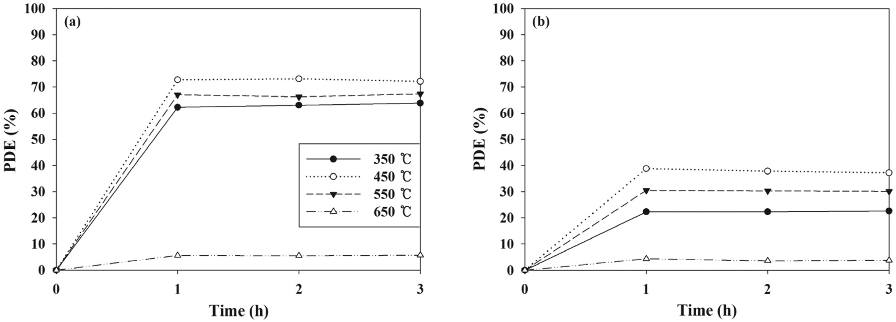
Photocatalytic control efficiencies of PANI-TiO2 composites were investigated under a variety of experimental conditions by varying the CT, FR, IC, and RH. Figure 1 presents the photocatalytic control efficiencies of PANI-TiO2 composites synthesized under different CT conditions over a 3-h photocatalytic process.
For both indoor air-level TCE and TTCE, the photocatalytic efficiency reached rapidly to maximum value in one hour, which was attributed to short photocatalytic oxidation times with less than 1 min (5.48-54.80 sec) in the plug-flow reactor systems used in this study. The average control efficiencies of PANI-TiO2 composites over 3-h photocatalytic process increased from 61 to 72% and from 21 to 39% for TCE and TTCE, respectively, as the CT increased from 350 to 450 ℃. However, for both the target VOCs, the average control efficiencies of PANI-TiO2 composites decreased gradually as the CT increased further to 550 and 650 ℃. These results were ascribed to different morphological
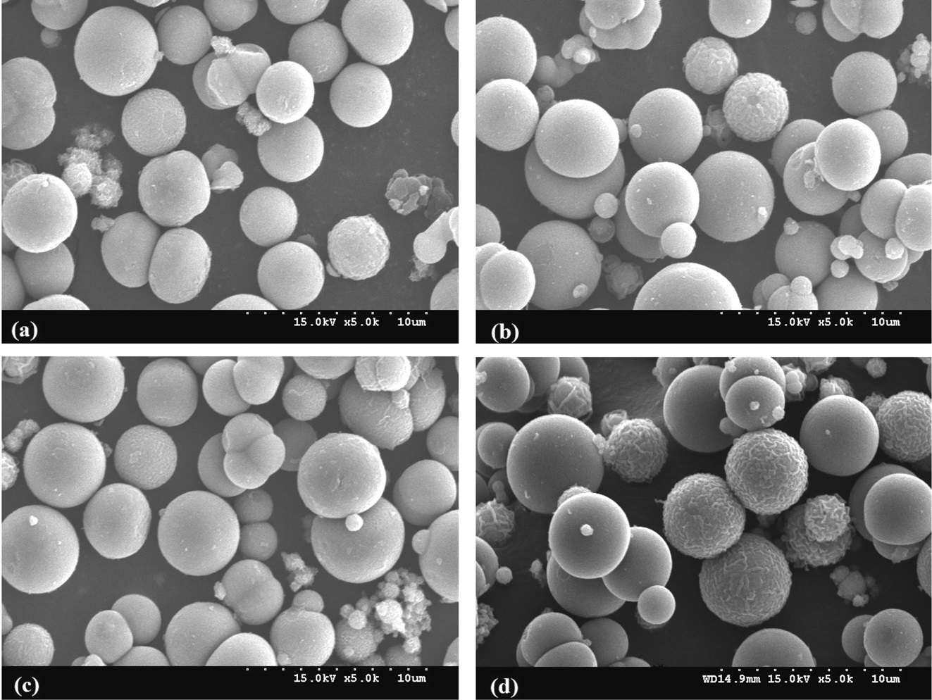
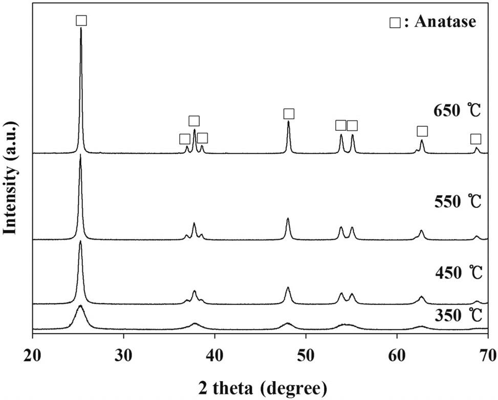
and electronic properties of PANI-TiO2 composites synthesized under different calcination temperature conditions, which could yield different photocatalytic behaviors. According to XRD results (Figure 2), all PANI-TiO2 composites showed rutile crystal phase but not anatase crystal phase, which were similar to results reported in previous studies[11,13]. However, more distinct peaks were observed for the PANI-TiO2 composite calcined at 450 ℃ compared to the PANI-TiO2 composite calcined at 450 ℃, suggesting superior photocatalytic performance of the former photocatalyst for the control of TCE and TTCE. Meanwhile, as shown in Figure 3, the SEM images reveals that the particle size of the PANI-TiO2 composites increased as the CT increased, thereby resulting in low volume-to-surface area for the composites calcined at higher temperature. This assertion was supported by the BET areas of PANI-TiO2 composites calcined at four different calcination temperatures (Table 1). Accordingly, the higher control efficiencies of the PANI-TiO2 composite calcined at 450 ℃ than the PANI-TiO2 composites calcined at 550 ℃ and 650 ℃ were attributed to high volume-to-surface area.
[Table 1.] BET surface area of PANI-TiO2 composites calcined at different calcination temperatures
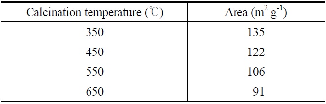
BET surface area of PANI-TiO2 composites calcined at different calcination temperatures
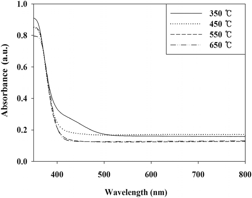
Moreover, the higher control efficiencies of the PANI-TiO2 composite calcined at 450 ℃ is supported by UV-VIS absorption intensity at UV range. Figure 4 exhibits that the PANI-TiO2 composite calcined at 450 ℃ could absorb stronger UV compared to the PANI-TiO2 composites calcined at 550 and 650 ℃, which would enhance photocatalytic performance for the removal of TCE and TTCE. It was notable that, even though the UV absorbance intensity of PANI-TiO2 composite calcined at 350 ℃ were stronger than that obtained from the PANI-TiO2 composite calcined at 450 ℃, the photocatalytic control efficiencies of PANI-TiO2 composite calcined at 350 ℃ were lower than those obtained from the PANI-TiO2 composite calcined at 450 ℃. These results suggested that the anatase crystal formation effect would outweigh UV absorbance effect on control efficiencies of TCE and TTCE.
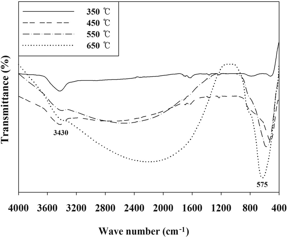
The FTIR spectra of the PANI-TiO2 composites synthesized at different CTs are presented in Figure 5. The FTIR spectra of
the PANI-TiO2 composites were similar to each other, although the transmittance intensity was somewhat different. Major absorption peaks appeared at bands of 3,430 and 575 cm-1. The band of 3,430 cm-1 was assigned to N-H stretching[12]. The low frequency bands around 575 cm-1 were likely due to the Ti-OTi vibration of anatase[17]. These findings confirmed the presence of anatase crystal phase in the PANI-TiO2 composites prepared in the present study, which supported the XRD results above. Meanwhile, no bands around 708 cm-1 which were associated with the Ti-O-Ti vibration of rutile[18,19], demonstrating again the absence of rutile crystal phase in the PANI-TiO2 composites prepared in this study. In addition, the band around 1,200 cm-1 was ascribed to the formation of C-O functional group[20].
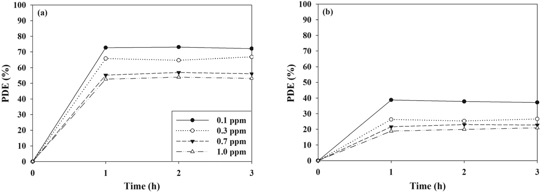
Figure 6 represents the control efficiencies the PANI-TiO2 composite calcined at 450 ℃ over a 3-h photocatalytic process ac-
cording to ICs that cover indoor air levels. For two target compounds, the photocatalytic control efficiencies exhibited a decreasing trend as IC increased. At the lowest IC (0.1 ppm), average control efficiencies of TCE and TTCE were 72 and 39%, respectively, whereas at the highest IC (1.0 ppm) they were 52 and 18%, respectively. The adsorption of pollutants on the surface of the catalyst was a major cause for the photocatalytic oxidation of chemical compounds[21,22]. This suggested that the increasing trend in control efficiency with increasing of IC would result from competitive adsorption between pollutant molecules on the photocatalyst surface. Moreover, at high ICs a limited amount of the adsorption sites on the surface of the PANI-TiO2 composites could be available for the adsorption of TCE and TTCE molecules before photocatalytic oxidation[22]. Consistently, Devahasdin et al.[23] reported that photocatalytic control efficiencies for nitrogen oxide (NO), which were determined via an UV-irradiated TiO2 system, decreased from 70 to 15% as IC increased from 5 to 60 ppm. Yu and Brouwers[24] also found that found that NO decomposition efficiencies, which were determined via a photocatalytic reactor with carbon-doped TiO2 under visible-light irradiation, decreased from 61 to 16 as IC increased from 0.1 to 1.0 ppm.
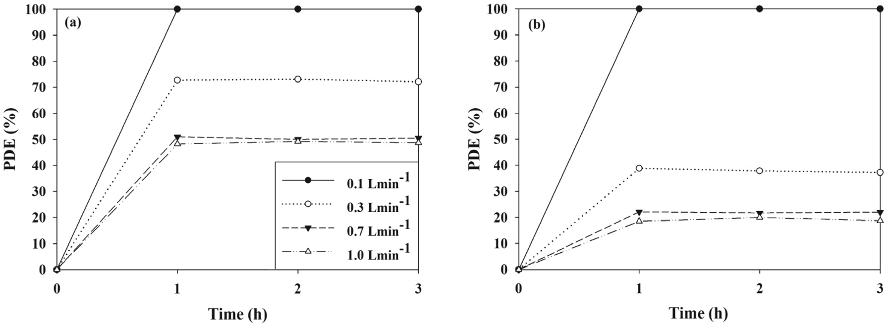
The control efficiencies of PANI-TiO2 composite calcined at 450 ℃ over a 3-h photocatalytic process according to FR are shown in Figure 7. For both the two target VOCs, the control efficiency decreased as the FR increased. Specifically, as the FR increased from 0.1 to 1.0 L min-1, the average control efficiencies of TCE and TTCE decreased from ca. 100 to 47% and ca. 100 to 18%, respectively. Similarly, Yu and Brouwers[24] reported that NO photocatalytic control efficiency decreased from to 62 to 13% as FR increased from 1 to 5 L min-1. The bulk mass transport of target compounds from the gas-phase to the surface of the catalyst particle is an important heterogeneous catalytic reaction process[25]. Accordingly, as FR increased, the bulk
mass transport of TCE and TTCE molecules would increase primarily owing to convection and diffusion. In addition, the retention times for the FRs of 0.1, 0.3, 0.5, and 1.0 L min-1, which were determined by dividing the reactor volume by the FRs, were 134, 45, 27, and 13 s, respectively. Accordingly, the lower TCE and TTCE control efficiencies for high FRs were assigned to an insufficient retention time in the photocatalytic reactor.
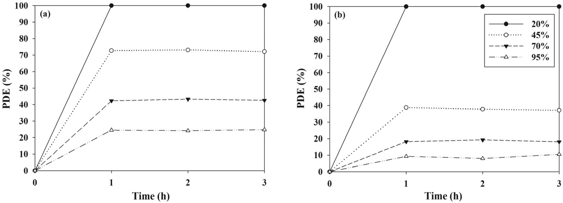
The effects of a wide range of RH values that cover both dried and humidified environmental conditions on the control efficiencies of TCE and TTCE were evaluated using the PANI-TiO2 composite calcined at 450 ℃ over a 3-h photocatalytic process. As presented in Figure 8, the control efficiencies of two target compounds decreased with increasing RH. Specifically, as the RH increased from 20 to 95%, the average control efficiencies of TCE and TTCE decreased from ca. 100 to 23% and ca. 100 to 8%, respectively. This pattern was consistent with that determined using a UV-irradiated TiO2 system, which was reported in Zhao et al.[26] study. Under low RH conditions, there is a shortage or absence of water molecules and as a result, photocatalytic reactions could be retarded owing to an insufficient hydroxyl groups, which could oxidize TCE and TTCE molecules on the surface of the PANI-TiO2 composites. On the other hand, excessive water vapor could compete with TCE and TTCE molecules for the adsorption sites on the surface of the PANI-TiO2 composites. Accordingly, low photocatalytic control efficiency under high RH conditions was ascribed to the competition between TCE or TTCE and water molecules for adsorption on the surface of the PANI-TiO2 composites. However, Jeong et al.[27] reported that photocatalytic efficiencies of a UV-irradiated TiO2 system for gaseous toluene control increased as RH increased from less than 1 to 50% and then remained constant while RH increased from 50 to 95%. In their study, an increased population of hydroxyl radicals, which would be formed due to
elevated water vapor, was provided as an explanation for the increase in toluene photocatalytic control efficiencies. Consequently, these contrasting RH effects on photocatalytic control efficiency were attributed to the amount of water vapor as well as the type and input concentration of target VOCs applied to this and previous studies.
The current study examined the application of PANI-TiO2 composites calcined at different temperatures for the photocatalytic control of indoor air level TCE and TTCE. Within the CT range specified in this study, the control efficiencies of the PANI-TiO2 composites fluctuated as the TiO2 ratio varied, without exhibiting any increasing or decreasing trend. These results were ascribed to contents of anatase crystal phase and specific surface area of different particle sizes in the PANI-TiO2 composites, which were demonstrated by the SEM and XRD images, respectively. In addition, the findings presented herein suggested that indoor air quality concentration levels, hourly air treatment volume, and indoor air humidity were all important parameters that should be considered to enable effective operation of the PANI-TiO2 composites for the photocatalytic control of indoor TCE and TTCE. Taken together, the results represented herein suggested that the PANI-TiO2 composite could be used efficiently for control of indoor chlorinated hydrocarbons, when photocatalytic operational conditions were optimized.