As new mobile devices such as cellular phones, PDAs, laptop computers, and touch screen computers become more and more popular, many people want to be able to access the internet without limitations. Rapid advances in various wireless access technologies such as wideband code division multiple access (WCDMA), mobile worldwide interoperability for microwave access (M-WiMAX), long term evolution (LTE), wireless local area networks (WLANs), and wireless sensor networks (WSNs) respond to consumers’ demands for mobile and ubiquitous computing environments.
As the number of network devices supporting the IPv4 protocol has been rapidly increasing, a shortage of IPv4 addresses to assign to new devices has arisen. To address the shortage in the IP address pool, the Internet Engineering Task Force (IETF) has proposed an IPv6 protocol with 64 bit addresses [1]. However, because mobility management is not supported in IPv6, Mobile IPv6 (MIPv6) [2] has also been standardized by the IETF. MIPv6 does not define a foreign agent (FA) and supports an optimized routing path through which a mobile node (MN) can communicate directly with a correspondent node (CN). Careful consideration has been required, however, to avoid a heavy and complicated MIPv6 protocol, which could cause several critical problems in wireless mobile devices, such as poor CPU performance, a large power consumption, and a shortened battery life. To overcome these problems in wireless environments, a network-based mobility management solution called Proxy MIPv6 (PMIPv6) [3] is standardized by the IETF Network- Based Localized Mobility Management (NETLMM) working group. In a PMIPv6 protocol, the mobility management function is performed by network equipment and only the IPv6 protocol stack is implemented in mobile devices for a light protocol. The PMIPv6 protocol includes two functional network entities: a local mobility anchor (LMA) and a mobile access gateway (MAG). A MAG detects the movement of an MN and initiates the mobility-related signaling with the corresponding LMA on behalf of the MN. A MAG establishes a bidirectional tunnel with an LMA through which packets for the MN are routed. A LMA is similar to a home agent (HA) in MIPv6, and the LMA contains the location information for MNs in a binding cache. Thus, a main role of an LMA is to maintain reachability to the MN’s address while the MN moves around within a PMIPv6 domain.
Currently, network mobility (NEMO) solutions are being developed by the IETF. A special mobile device called the mobile router (MR) is introduced in NEMO. The MR is located in a vehicle and provides mobile devices with a communication link to the internet. The mobility framework of the NEMO basic support protocol (BSP) [4] is Mobile IPv6. In order to support the transparent access to the internet, MIPv6 should be implemented in both MRs and MNs. In order to overcome several problems of the MIPv6 protocol, some researchers are studying PMIPv6 protocols instead of MIPv6. In this paper, we propose a novel scheme that removes excessive tunnels and increases the utilization of wireless resources in PMIPv6-based NEMO environments.
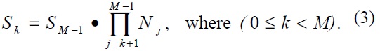
The remainder of this paper is organized as follows. In Section II, we present related works about PMIPv6-based NEMO. In Section III, we propose the novel scheme. In Section IV, we provide a performance analysis on the proposed scheme and in Section V, we show various numerical results. Finally, we conclude this paper in Section VI.
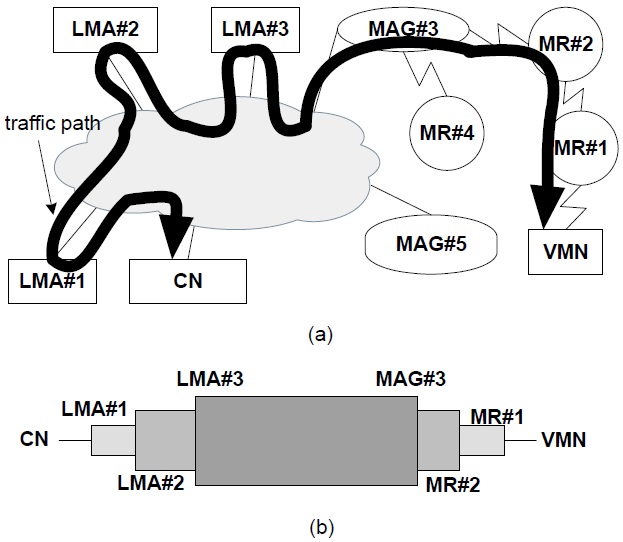
A representative solution for PMIPv6-based NEMO called N-PMIPv6, is proposed in [5]. The key idea of NPMIPv6 is to extend the PMIPv6 domain to also include mobile networks. The MR operating in the N-PMIPv6 protocol performs a similar function to the MAG in a PMIPv6 protocol. For example, consider the simple MIPv6 network shown in Fig. 1, where some MNs are attached to a specific MR, and the MR initiates a binding update to the corresponding LMA. A visiting mobile node (VMN) denotes a mobile node (MN) that is outside its home network. When MR#1 detects an attachment from the VMN, it sends a signaling message to the corresponding LMA managing the VMN’s address. That is, on behalf of the VMN, MR#1 initiates MIPv6’s signaling procedures and deals with related messages from the corresponding LMA. Similarly, when MR#1 attaches to MR#2, MR#2 deals with signaling messages on behalf of MR#1. Because N-PMIPv6 is a representative solution, we will make a comparison between our scheme and the N-PMIPv6 scheme in the next section. Although N-PMIPv6 is simple and scalable, a nested NEMO environment causes an inefficiency in wireless resources and the non-optimal routing path shown in Fig. 1(a). For example, multi-tunnels cause a large overhead and data packets may travel along several LMAs, as shown in Fig. 1(b). In [6], the N-NEMO scheme is proposed. N-NEMO is based on a tunnel splitting scheme composed of two parts: the global tunnel that is established between an LMA and a MAG, and a local tunnel that is established between the MR and the MAG. This tunnel splitting scheme has greater data efficiency, using less packet overhead, and reduces the latency of the packet transmission using a more optimal route. However, it does not consider multiple LMAs, and various handover procedures are not clear. A Tunnel Compress Scheme (TCS) is proposed in [7], which compresses the multi-tunnels of a routing path into two separated tunnels; one tunnel is established from MAG to LMA and the other tunnel is established from MAG to MR. Consequently, the TCS scheme reduces the inefficiency of wireless utilization and the non-optimal routing path as in N-NEMO. However, this network mobility scenario is ambiguous, and a few simulation results are not sufficient to explain the properties of the TCS scheme. In addition, the performance of the TCS scheme is not analyzed, and there is one compressed tunnel in the wireless path. In this paper, we eliminate the wireless tunnel and describe the performance analysis.
Many route optimization schemes in NEMO [8] and PMIPv6 [9] are related to our interests. However, a combined study of both PMIPv6 and NEMO environments is required.
Fig. 1 illustrates two parts of a packet’s routing path in NPMIPv6. The first part is the wire-line section that the data packets travel through several LMAs. Because there are three nested levels and each different LMA manages the home network prefixes (HNPs) of both the MRs and VMNs, packets for the VMN travel through three LMAs. Two of the three LMAs are not essential entities and thus the wire-line part of the routing path is not optimal in Fig. 1. In order to overcome this non-optimal routing path of N-PMIPv6, our tunnel-free scheme (TFS) proposed in this paper establishes only one tunnel between the VMN’s LMA and the MAG. That is, because packets for the VMN do not pass though LMA#2 and LMA#3 in the TFS scheme, the routing path of the TFS scheme is more optimal than that of the N-PMIPv6. The second part of the routing path is a wireless section consisting of one MAG, several MRs, and VMNs. The TFS scheme removes all of the tunnels in the wireless section between the MAG and the VMN. Instead of multi-tunnels, the host-based routing is performed in our TFS scheme. The multi-tunnel problem of N-PMIPv6 reduces the utilization of wireless resources and causes unnecessary packet fragmentation. In summary, the TFS scheme optimizes the route path of the wire-line section and removes all tunnels of the wireless section. Additionally, due to the route path optimization of the wire-line section, the number of related LMAs is decreased and thus the load to the LMA may be reduced.
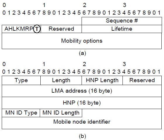
N-PMIPv6 uses a proxy binding update (PBU) message to register a node’s locations at the LMA. To support the TFS’s operations, an extended PBU message is defined in Fig. 2. The TFS’s PBU message of the wire-line section is the same as the N-PMIPv6’s PBU message, and the extended PBU message is deployed only in the wireless section. An extended PBU message includes a T-flag that denotes the TFS’s operation. Multiple TF options may be appended in an extended PBU message to register the routing table of both the MRs and a MAG. In addition, a MAG establishes a direct tunnel with an LMA, of which the information is recorded in a TF option. In order to provide full details of the TFS scheme in the network topology in Fig. 1(a), we handle several scenarios as follows.
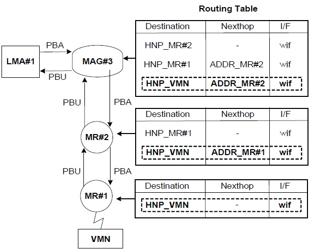
Fig. 1(a) shows that MR#2 is attached to MAG#3 and MR#1 is attached to MR#2. When a VMN joins MR#1, MR#1’s L2 detects the new connection with the VMN and obtains an LMA address from the Authentication, Authorization and Accounting (AAA). The interaction between MR#1 and the AAA is based on the authentication protocol, but this is beyond the scope of the current study. If the N-PMIPv6 protocol is used, MR#1 generates a PBU message of which the target address is LMA#1 on behalf of the VMN. However, in the case of the TFS scheme, the target address of an extended PBU message is not LMA#1 but the next-hop address. Thus, an extended PBU message is relayed from node to node in a wireless section. The TF option for the VMN is appended to an extended PBU message by MR#1. After MR#1 saves both its TF options and a source address into an internal memory, then it forwards an extended PBU message to the next-hop entry in the direction of the MAG as shown in Fig. 3. After the MAG finally receives an extended PBU message from MR#2, it carries out a binding update by exchanging the ordinary PBU/proxy binding acknowledgement (PBA) messages with the LMA recorded in a TF option. Upon receiving a PBU message from the MAG, the LMA determines whether it accepts the request of the binding update or not. A PBA message contains a status field that represents a success or failure code in this binding update. If a success code is included in a PBA message, it triggers routing table updates of both the MAG and the MRs in the wireless section. On registering a routing entry for the VMN, both the MAG and the MRs use the internal information such as the TF option and a source address, and check other information such as the home network prefix (HNP) option in a PBA message. There are two major parts in an entry of a routing table: a destination field contained in the HNP option of a PBA message, and a next-hop field that is the source address of the PBU message.
The TFS scheme requires a large memory for storing TF options, a source address of the PBU message, and an additional entry of the routing table.
Let’s assume that an external CN sends a data packet to the VMN. In the case of N-PMIPv6, data packets from a CN to a VMN travel along LMA#1, LMA#2, and LMA#3 through nested tunnels as shown in Fig. 1. However, in our TFS scheme, the data packets are routed to LMA#1 and are encapsulated from LMA#1 to MAG#3. In MAG#3, these data packets are decapsulated and then forwarded to MR#2 by a routing table. Because the destination address of the data packets is matched with a HNP of the VMN, these data packets are forwarded to MR#2, the next-hop node. Similar operations, such as looking up a routing table, are performed in both MR#2 and MR#1. Finally, because the next-hop address field is blank in the routing entry of MR#1, the data packets are forwarded directly to the VMN.
>
B. Intra-MAG Handover of VMN
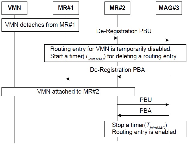
Although a VMN moves outside an attached MR, it may reside in the same MAG’s area. This is a handover event within a MAG called the intra-MAG handover. For example, if a VMN connected to MR#1 is moving to MR#2’s area in Fig. 1, then this type of movement results in an intra-MAG handover. Because the tunnel of the TFS scheme is terminated at the MAG, the topology change in a wireless section does not affect the tunnel between an LMA and a MAG. Thus, in the TFS scheme, a binding update of an intra-MAG handover is limited only to the wireless section and does not propagate into the wire-line section. Those binding update-related messages are called local PBU (LPBU) and local PBA (LPBA) messages. A signaling procedure of an intra-MAG handover is shown in Fig. 4. As the VMN is detached from MR#1, the de-registration PBU message is initiated by MR#1. When a de-registration PBU message is relayed to MR#2, a routing entry in the MR#2 for the VMN is temporarily disabled and MR#2 triggers a temporary timer (
>
C. Inter-MAG Handover of VMN
When the VMN is removed from the current MAG’s area and enters the new MAG’s area, the inter-MAG handover occurs. In the old MAG and the old MRs, a temporary timer,
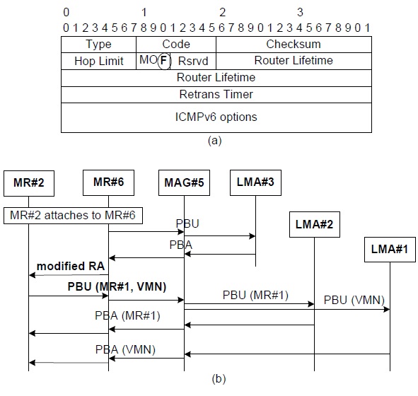
NEMO defines a special device (e.g., MR), which can move into any place with the same IP address, even in a visiting network. Therefore, the TFS scheme needs to support the MR’s mobility in various scenarios. If MR#2 detaches from MAG#3 and attaches to MR#6 of MAG#5 as in Fig. 1, an inter-MAG handover is triggered that includes both MR#1 and a VMN. MR#6 detects the attachment of MR#2 and exchanges PBU and PBA with MAG#5 and adds a routing entry for MR#2. In addition, MAG#5 establishes the tunnel with LMA#3 and adds a routing entry for MR#2. The procedures of both binding registration and the routing table update are the same as Scenario A. MR#6 can be aware of an attachment to MR#2, but cannot sense what nodes are hidden behind MR#2. To request a binding update for the hidden nodes in the TFS scheme, we define a modified router advertisement (RA) as in Fig. 5(a). In NPMIPv6, an RA message is sent with an HNP in an option field. In the TFS scheme, a modified RA message includes two new fields: the F-flag, which is used to trigger a binding procedure for hidden nodes, and an HNP field. In this scenario, when MR#6 receives a modified RA message, it performs the binding update on behalf of two hidden nodes, MR#1 and the VMN. Because MR#2 maintains the hidden nodes’ TF options and the routing entries for both MR#1 and the VMN, it already knows the binding-related information about MR#1 and the VMN. Therefore, MR#2 sends a PBU message with all of the hidden nodes’ TF options as in Fig. 5(b). In that time, a PBU message operates as a group registration message for all of the hidden nodes.
MAG#5 constructs each node’s ordinary PBU message from an extended PBU message. Separately, each PBA message is responded to by each LMA and each routing entry is added in MR#6 and MAG#5. All TF options of both MR#1 and the VMN are also saved in MR#6 and MAG#5 along with the routing entries, as in scenario A.
In comparison with N-PMIPv6, the TFS scheme has some disadvantages in a MR handover scenario. It is unnecessary for hidden nodes to update their locations in N-PMIPv6. However, because the TFS scheme requires additional signaling procedures for hidden nodes, both the signaling overhead and the handover latency may increase. Nevertheless, there is room for improvement. There are two parts in the signaling procedure of Fig. 5(b). The first part is a handover procedure of representative node MR#2, and the second part is the handover procedure of hidden nodes MR#1 and the VMN after receiving a modified RA. Because it is required that these binding procedures take place in sequence, the handover latency is larger than that of N-PMIPv6. The simultaneous binding procedures may be considered a further research item. Two separate handover procedures of both the representative node and hidden nodes can proceed simultaneously after MR#2 and MR#6 detect the attachment of other nodes. This simultaneous procedure will contribute a reduction in the handover latency. However, because this is outside the scope of our current study, we describe this simultaneous binding as a possibility to improve the handover performance of the TFS scheme. Furthermore, in our TFS scheme, several binding updates from the MAG to the LMA are processed separately as shown in Fig. 5(b). If the bulk update procedure can be defined as bulk re-registration [10], the number of signaling messages can be significantly reduced.
In this intra-MAG handover, we assume that MR#2 moves to MR#4 in the same MAG#3. This scenario’s signaling procedure is similar to that of scenarios B and D, but because it does not move to another MAG, the interaction between a MAG and a LMA is not required. Thus, a PBU message from MR#4 is terminated at MAG#3, and a PBA message is responded to by MAG#3. The exchanges of PBU and PBA messages are limited only in the wireless section and are used in the routing table update of immediate MRs.
A CN may be a fixed node at a wire-line section or a MN in a wireless section. Thus, if a CN is connected to the same MAG with the VMN, there is a short path between the CN and the VMN. However, data packets should always go through a distant LMA. Because the LMA performs important functions in packet delivery, statistics gathering, accounting, and various other functions for mobile nodes, data packets should transfer through the LMA. However, the forwarding path of a data packet is not optimal and results in an unnecessary delay for packet delivery. If there are no problems in other functions such as statistics gathering and accounting, it is optimal that data packets from the VMN are directly forwarded to the CN. Thus, we call this direct forwarding policy local routing. If local routing for the VMN is enabled in either an MR or a MAG, a data packet to the VMN is not tunneled to the LMA and is directly forwarded. This local routing scheme can be feasible by defining a flag in the AAA. When a MN is attached, various policies can be obtained from the AAA. By adding a flag for the local routing policy per the MN, it is easy to control a local routing policy.
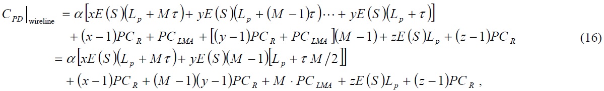
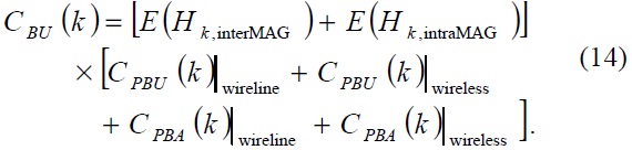
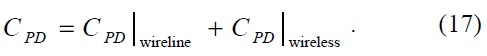
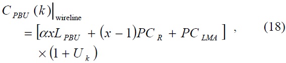
In this section, we present our analysis and comparison of the performance on N-PMIPv6 and our TFS scheme. In order to compare the performance of different protocols, we use the protocol cost as the performance metric, as used in other research studies [6,9,11,12]. The total cost of a MIPv6-related protocol is the sum of the cost of a binding update and a packet delivery, which is shown in Eq. (1).

The cost of a binding update,
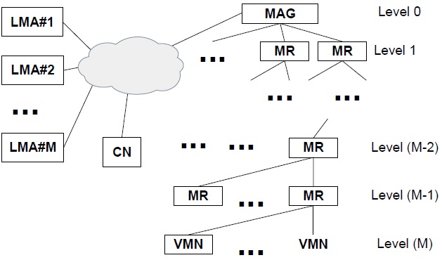
In order to analyze the performance of our TFS scheme, we assume a network model as in Fig. 6. It is assumed in Fig. 6 that the nested level is
There are many moving nodes such as the MRs and VMNs in Fig. 6. For simplicity, we consider one type of a mobility model per nested level and calculate the protocol cost with the assumption that a node of a specific nested level moves and all nodes of the other nested levels are fixed. We define the following new parameters as
While the packet delivery cost is independent from the mobility model, the cost of the binding update is dependent on the mobility model. Thus, we can get the summation as follows:
For the convenience of analyzing the performance of both N-PMIPv6 and the TFS scheme, we assume that the cell size of a MR in level
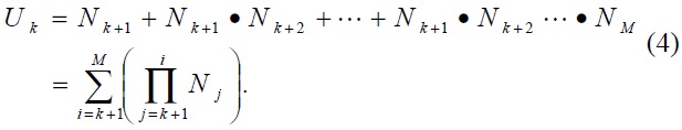
In the case of the MR’s handover, the TFS scheme requires the binding update for hidden nodes. We therefore calculate the number of hidden terminals in view of an MR of level
We also make the following additional assumptions to derive the mobility and traffic models.
- The session arrival process follows the Poisson distribution with rate λs.
- There are no inter-level handovers. That is, neither MRs nor VMNs at level k move to the other MR or MAG at different levels, except level k. Although this assumption is considered unreasonable, it is not problematic when comparing protocol costs and major properties of different MIPv6-related protocols.
- The residence time during which an MR and a VMN stay in the given area follows an exponential distribution.
Let
where (0 <
where (0 <

On the same occasion, we get the average number of inter-MAG handovers during a session interval as follows:
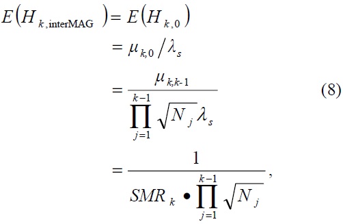
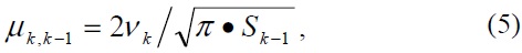
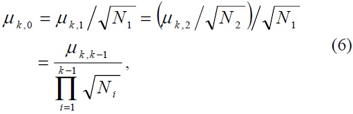
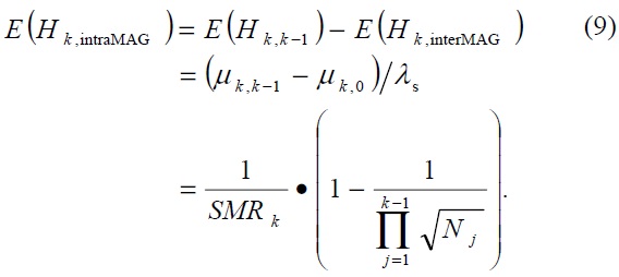
where the session-to-mobility ratio (SMR) at level
We define here several notations for explaining our cost model in detail:
- τ : IPv6 tunneling header size, 40 bytes
- ? : TF option size for one mobile node, 44 bytes
- α : transmission unit cost in wired link, 1
- β : transmission unit cost in wireless link, 1.5
- LPBU : PBU message size, 76 bytes
- LPBA : PBA message size, 76 bytes
- LRA : RA message size, 76 bytes
- PCR : processing cost in a router, 8
- PCMR : processing cost in a MR, 10
- PCMAG : processing cost in a MAG, 12
- PCLMA : processing cost in a LMA, 24
- dVMN?MAG : hop distance from VMN to MAG, M hops
- dMAG?LMA = dLMA?MAG : hop distance from MAG to LMA, 20 hops
- dLMA?LMA : hop distance from LMA to LMA, 8 hops
- dLMA?CN : hop distance from LMA to CN, 10 hops
>
B. Performance Analysis of N-PMIPv6
Because each MR operates as a MAG in N-PMIPv6, it exchanges PBU and PBA messages with an LMA. In order to calculate the cost of a binding update with the assumption that a mobile router of level
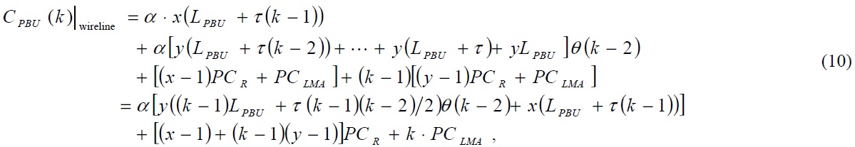
where

where
where
calculated as follows:
If we combine Eqs. (14) and (2), then we can obtain the total cost of a binding update in N-PMIPv6.
Let
>
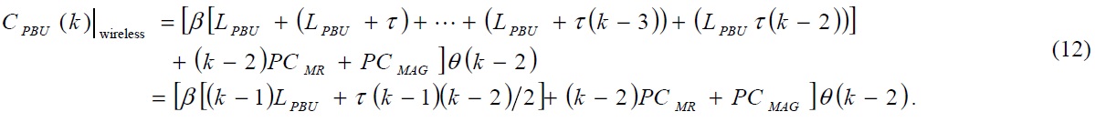
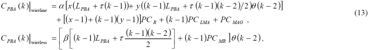
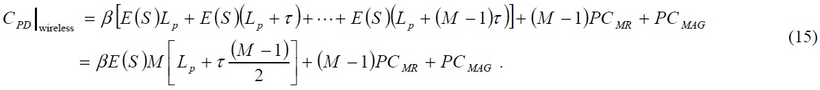
C. Performance Analysis of TFS
As the specific node at level
where
In this section, we present and compare the performance results of N-PMIPv6 and TFS. For any numerical result in


where

where
which specific system parameters are not provided, the following parameters are used.
- M = 3: the nested level of a wireless section
- SM?1 = π?(10)2 ? 314 m2 : the communication area of MR at level (M-1)
- [N1, N2, N3] = [100,10, 2] : the number of nodes connected to one MR or MAG at each level
- [v1, v2, v3] = [20, 5, 2] : the velocity (m/s) of nodes at each level
- E(S) = 45 : the average length of a session in the packets
- LP = 300 : the average packet length in bytes
With a fixed session arrival rate
[Table 1.] Cost of a binding update according to the weighting factor
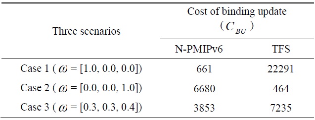
Cost of a binding update according to the weighting factor
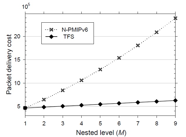
Fig. 7 shows the difference in the packet delivery cost as a function of various nested levels. As the nested level becomes larger in N-PMIPv6, the packet length becomes larger with nested tunnels and should travel around many LMAs. On the other hand, it is shown in Fig. 7 that the TFS scheme seems insensitive to a change in the nested level. Due to both the route optimization of the wire-line section and the tunnel-free mechanism of the wireless section, the packet delivery cost is much lower than that of N-PMIPv6. However, since the packet delivery cost dominates the signaling performance, our TFS scheme ultimately outperforms N-PMIPv6.
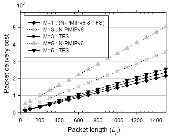
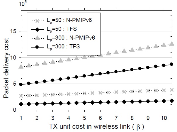
The relationship between the packet delivery cost and the packet length is shown in Fig. 8. As the packet length increases, the packet delivery cost of N-PMIPv6 increases rapidly. The main reason for this large increase is the nonoptimal routing path of N-PMIPv6. In the case that the nested level is 1, because there is no tunnel in a wireless section and one tunnel between the MAG and the LMA, the packet delivery cost of the TFS scheme is the same as that of N-PMIPv6. When the nested level is larger than 1, nested tunnels are heavily overlapped in N-PMIPv6 and thus the performance difference becomes conspicuous due to the non-optimal routing path. The performance difference of the packet delivery cost is hundreds or thousands of times larger than that of the signaling cost. That is, although the signaling cost of the TFS scheme is slightly higher than that of N-PMIPv6, the TFS scheme outperforms N-PMIPv6 from the point of view of the total protocol cost. When the average length of the session is larger, the performance difference between N-PMIPv6 and TFS becomes greater. Moreover, as shown in Figs. 7 and 8, the performance variations are relatively small in the TFS scheme.
A greater weight is generally assigned to a one-hop distance in a wireless section than in a wire-line section. This is because the wireless resource is more precious and expensive than the wire-line resource. It needs more time and more cost to send the same amount of data packets in the wireless section than in the wire-line section. When a packet travels along the same hop distance in both a wireline and a wireless section, the protocol cost is larger in the wireless section than it is in the wire-line section. In the performance analysis, we define the notation
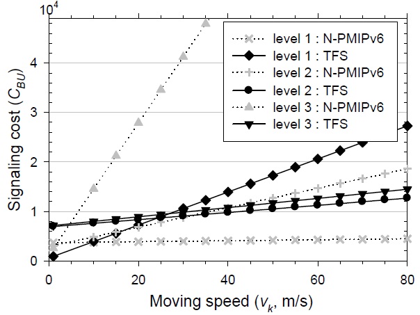
When the nested level is 3, the velocity of each level’s node, [
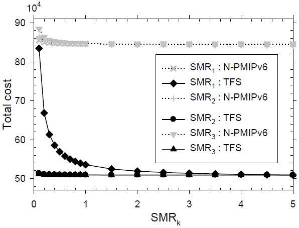
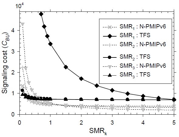
In Fig. 11, the signaling performance is described according to the variation of each level’s SMR. The default values at each level for the SMR are
In this paper, we propose the TFS that removes nested tunnels in a wireless section and optimizes the routing path in a wire-line section. Instead of nested tunnels in a wireless section, the TFS scheme uses a host-based routing table and optimizes the routing path between the MAG and the LMA. By removing nested tunnels, the wireless resource utilization is improved and packet fragmentation may be avoided. With routing path optimization, the hop distance between the MAG and the LMA is reduced and mitigates the load of the LMA. As described in our numerical results, the signaling cost of the TFS scheme may be higher than that of N-PMIPv6 in some cases. However, in view of the packet delivery cost, the TFS scheme outperforms N-PMIPv6. Additionally, as the nested level is larger, the TFS scheme provides remarkably better performance than N-PMIPv6. For further research, we are developing a modification of the TFS scheme as a routing optimization method.