Suppressing or mitigating signal distortion due to group velocity dispersion and optical Kerr effects is necessary in ultrahigh speed and long-haul wavelength division multiplexing (WDM) transmission systems. Dispersion management (DM), optical phase conjugation (OPC), and the combination of these two are promising techniques to compensate for signal distortion. In this paper, to implement a flexible optical WDM network, a new optical link configuration with a randomly distributed single-mode fiber (SMF) length and fixed residual dispersion per span in the combination of DM and OPC is proposed and investigated. The simulation results show that the best net residual dispersion (NRD) in the proposed optical links is +10 ps/nm, which is independent of pre- and postcompensation. The effective launch power of the WDM channel is increased more in the optical links with NRD = +10 ps/nm controlled by only precompensation. Furthermore, the system performance difference between the proposed optical link configuration with the best NRD and the conventional optical link with uniform distribution of the SMF length had little significance. Consequently, it is confirmed that the proposed optical link configuration with the best NRD is effective and useful for implementing a reconfigurable long-haul WDM network.
Group-velocity dispersion (GVD) and optical nonlinearity are the major limiting factors in high-speed long-distance fiber-optic transmissions, such as wavelength division multiplexing (WDM) systems with a 40 Gbps channel data rate [1]. In such systems, as the transmission distance and span length under the required optical signal-to-noise ratio are increased, the launch power has to be increased. Thus, the nonlinear Kerr effect becomes one of the most important impairments. Optical phase conjugation is a promising technique to compensate for these nonlinear impairments [2-4]. The concept is based on optical phase conjugation in an optical phase conjugator (OPC) placed at the middle of a fiber transmission link. The phase conjugated signal generated by the OPC carries the same data as the original signal but the signal spectrum is inverted. This technique offers unique advantages over other competitive methods such as data rate and modulation format transparency, ultra-fast responses, simultaneous multi-channel compensation, and compensation of nonlinear distortions. It is independent of the transmission fiber’s dispersion property as long as the same type of fiber is used for both halves of the transmission link.
To minimize the impact of distortion due to GVD only, a dispersion map involving optical pre- and postcompensation as a dispersion management (DM) technique has also been developed [5-7]. Pre- and postcompensation are defined as dispersion compensation using dispersion compensating fiber (DCF) after the transmitter and before the receiver, respectively. In the case of a dispersion map applied to every fiber span, residual dispersion per span (RDPS) is defined as the dispersion accumulated in each fiber span, and net residual dispersion (NRD) is defined as the total dispersion accumulated at the end of the transmission link. These quantities are key parameters for designing a transmission system with high performance. Generally, NRD is decided by controlling preor postcompensation and RDPS. The most advanced DCFs are even capable of slope-matching compensation, namely, compensating the dispersion and the dispersion slope of the transmission fiber simultaneously. However, the DM technique using DCF is used only in optical links without nonlinear effects on optical signals. That is, DM can compensate for distorted optical signals due to only GVD.
In the optical phase conjugation technique, compensation for nonlinearity by OPC is limited by the asymmetry of the strength of the Kerr effect along the fiber with respect to the OPC position. However, there are a number of techniques for overcoming this drawback. For example, optimizing the OPC position [8,9] or combining appropriate dispersion mapping [8], [10,11] has been proposed recently. In order to suppress the nonlinearity impairments to a large extent, the system parameters of an OPC link, such as the location of the OPC or the dispersion map, need be optimized.
In a previous work, the author has also shown that a 960 Gbps (40 Gbps × 24 channels) WDM transmission system with good receive performance was implemented by applying the combined DM and OPC into optical links [12]. In this research, the basic scheme of DM is that the system NRD is controlled by precompensation using DCF of the first span, postcompensation using DCF of the last span, and RDPS of the same value in the rest of the fiber spans. The single-mode fiber (SMF) length of every fiber spans between an erbium-doped fiber amplifier (EDFA) are assumed to be equal, for simplicity of optical link configuration in the previous work. However, the SMF length needs to be unlimited for flexible implementation of the optical network topology. As far as the author knows, the analysis and
assessment of a WDM transmission link to which OPC and DM are applied, with random distribution of the SMF length in every fiber span, have not been reported yet.
Therefore, in this work, optimal NRDs are induced by assessing the eye opening penalty (EOP) of the worst channel among the 24 WDM channels in optical links with randomly distributed SMF length and a fixed 150 ps/nm of RDPS in every fiber span. Also, the effective launching powers of WDM channels in the optical links with the induced optimal NRD are presented to meet the design requirements of the flexible ultra-high optical transmission network.
>
A. Modeling of Optical Links
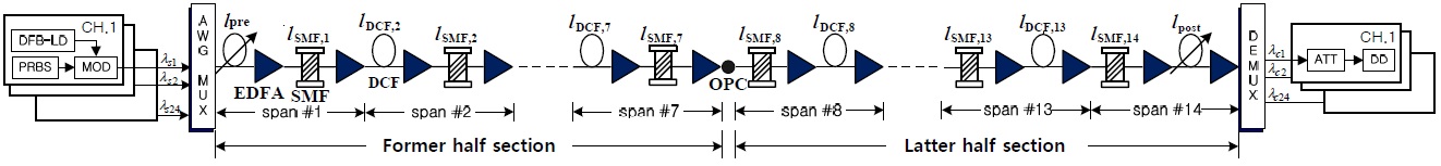
The optical transmission link configuration investigated in this research is shown in Fig. 1. The total transmission links consist of 14 fiber spans, which include SMF and DCF. The SMF length of all of the spans are designed to be fixed at
In order to generate symmetric distribution of dispersion with respect to OPC, the DCFs are placed before each SMF in earlier half section from the transmitter (Tx) to the OPC, while the DCFs are placed after each SMF in the latter half section from the OPC to the receiver (Rx), as illustrated in Fig. 1. The DCF length
In this research, the averaged SMF lengths were assumed to be equal to 80 km in both transmission sections in the case of random distribution. Namely, the SMF length of each fiber span was randomly selected to be one value among 50, 60, 70, 80, 90, 100, or 110 km in each half section; thus the averaged SMF length of one fiber span became 80 km, according to Σ
The NRD is controlled by pre- or postcompensation in both cases of uniform distribution and random distribution of SMF length, as plotted in Fig. 1. In case of determining the NRD by only precompensation, the NRD depends on the variable length of the first DCF, i.e.,
>
B. Modeling of WDM Transmission System
The WDM system consisted of Tx, Rx, the dispersion The WDM system consisted of Tx, Rx, the dispersion managed optical links, and the OPC nearby the midway of total transmission length. The Tx (Fig. 1) was assumed to be a distributed feedback laser diode (DFB-LD). The center wavelength of the DFB-LD was assumed to be 1550?1568.4 nm by spacing of 100 GHz (0.8 nm) based on ITU-T recommendation G.694.1. Thus, if each wavelength was allocated for one WDM channel, the total wavelength considered corresponds to 24-channel WDM transmission. The DFB-LD was externally modulated by an independent 40 Gbps 128 (= 27) pseudo random bit sequence (PRBS). The modulation format from the external optical modulator was assumed to be return-to-zero (RZ), and the output electric field of the RZ format was assumed to be a secondorder super-Gaussian pulse with a 10 dB extinction ratio, duty cycle of 0.5, and chirp-free.
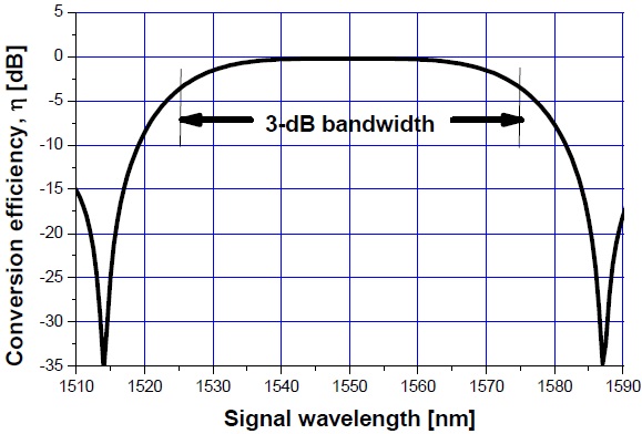
The nonlinear medium of OPC midway along the total transmission length is highly nonlinear dispersion-shifted fiber (HNL-DSF). The parameters of OPC using HNL-DSF are as follows: loss of HNL-DSF
as shown in Fig. 2. The signal wavelengths were converted to 1549.5?1528.5 nm (these are called the conjugated wavelength) through OPC. Thus, the 24 signal wavelengths and these conjugated wavelengths belonged within the 3-dB bandwidth of
The conjugated wavelengths are sent into the Rx of direct detection. The Rx consists of the pre-amplifier of EDFA with 5 dB noise figure, the optical filter of 1 nm bandwidth, PIN diode, pulse shaping filter (Butterworth filter), and the decision circuit. The receiver bandwidth is assumed to be at 0.65 × bit-rate [2].
III. NUMERICAL ASSESSMENT METHOD
The propagation of the signal in a lossy, dispersive, and nonlinear medium can be expressed by the nonlinear SchrOdinger equation, assuming a slowly varying envelope approximation [1]:
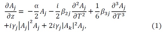
where
The EOP was used to assess the system performance of the receiving WDM signals in this work, as shown in the following equation:
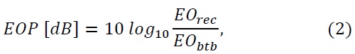
where
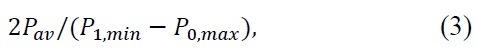
where
There are many random distribution cases of SMF length. It is difficult to assess the system performance of the overall cases because it is a time consuming process. Therefore, in this work, 10 cases of random distribution are considered for an accurate and simple assessment.
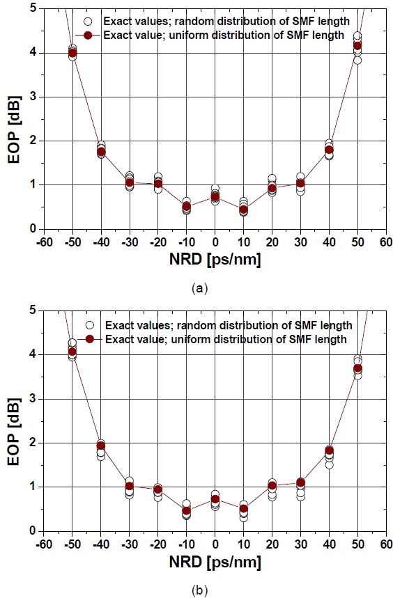
Fig. 3a and b illustrate EOPs of the worst channel among the 24 WDM channels with launching power of -2 dBm as a function of the NRD controlled by pre- and postcompensation, respectively, in optical transmission links with the randomly distributed SMF length. Fig. 3 also includes the EOP obtained from optical links with a uniform distribution of the SMF length in order to compare the two. It is shown that the EOPs depend on the NRD as well as the SMF length distribution. It is confirmed that the optimal NRDs were found to be 10 ps/nm or -10 ps/nm in the optical link controlled by pre- and postcompensation for uniform and random distributions of the SMF length because the EOPs were the smallest values at these NRDs. Through analysis of the results of Fig. 3, it is also confirmed that the EOP depends upon the pattern of the SMF length random distribution. Namely, in the optical links with the randomly distributed SMF length, it is predicted that the deviation of the EOP will depend on the launch power of the WDM channels as well as the distribution pattern of the SMF length.
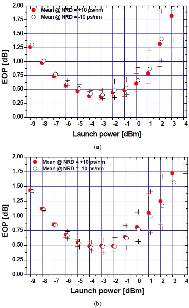
Fig. 4a and b show the worst channel’s mean EOPs and EOP deviations as a function of the channel launch power at the optimal NRD obtained. In Fig. 4, the symbols ‘●’ and ‘○’ express the mean EOP obtained from 10 random patterns at optimal NRD, and ‘+’ is the deviation of these EOPs. From Fig. 4, it is confirmed that the deviation of the EOP as well as the mean EOPs increase as the channel launch powers increase in the range above -4 dBm. Namely, EOPs are less affected by random distribution of the SMF length at a relatively small launch power.
It is also shown that, in optical links with optimal NRD controlled by precompensation, i.e., in Fig. 4a, the mean EOPs and EOP deviations obtained at the NRD of 10 ps/nm are less than those obtained at the NRD of -10 ps/nm, for the entire launch power range considered. In addition, in optical links with optimal NRD controlled by postcompensation, i.e., in Fig. 4b, though the mean EOPs and EOP deviations obtained at the NRD of -10 ps/nm are slightly less than those obtained at the NRD of 10 ps/nm, the differences between the two cases are negligible, in the range below -2 dBm. On the other hand, in Fig. 4b, the mean EOPs and EOP deviations obtained at the NRD of 10 ps/nm are less than those obtained at the NRD of -10 ps/nm, for the range above -3 dBm. Therefore, it is confirmed that the best NRD is +10 ps/nm in the optical link with the randomly distributed SMF length, which is independent of pre- and postcompensation required for deciding the NRD.
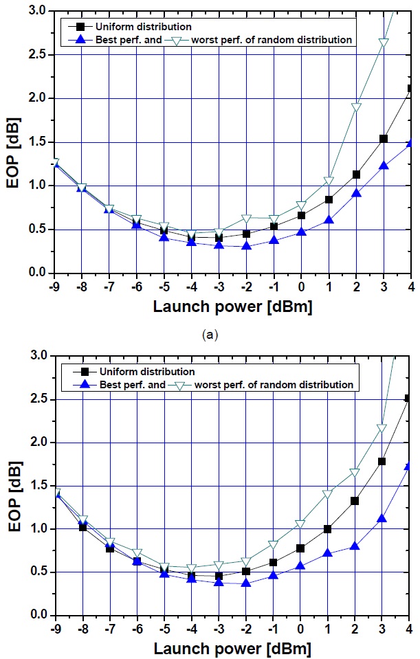
Fig. 5a and b show the worst channel’s EOPs as a function of the channel launch power at the obtained optimal NRD of 10 ps/nm and -10 ps/nm, which is controlled by pre- and postcompensation, respectively. If the criterion value of the EOP for excellent reception performance is selected to be 1 dB EOP, then the launch power resulting below 1 dB EOP is defined as the allowable launch power. In the optical link with NRD = 10 ps/nm controlled by precompensation, the allowable launch power values are obtained to be -8 to 2.3 dBm and -8 to 0.8 dBm for the distribution pattern of SMF length resulting in the best system performance and the worst performance, respectively. Namely, at the high launch power range, the deviation in the effective launch power is almost 1.5 dB depending on the random distribution pattern of the SMF length.
On the other hand, in the optical link with NRD = -10 ps/nm controlled by postcompensation, the allowable launch power values are obtained to be -7.7 to 2.6 dBm and -7.6 to - 0.3 dBm for the distribution pattern of the SMF length resulting in the best system performance and the worst performance, respectively; namely, the deviation in the effective launch power is almost 2.9 dB in the high power range. Therefore, the deviation in the effective launch power depending on a random pattern in the optical link with -10 ps/nm controlled by postcompensation is larger than that in the optical links with 10 ps/nm controlled by precompensation.
It is practically difficult to determine the specific pattern of random distribution of the SMF length for obtaining the best system performance. Thus, it is necessary to consider the worst case, that is, a random distribution pattern obtaining the worst system performance for implementing the flexible optical transmission links. From this viewpoint, the best NRD will be 10 ps/nm controlled by precompensation, and simultaneously, the launch power of the WDM channel will be from -8 dBm to almost 1 dBm in optical links with a multi-span of the randomly distributed SMF length and the fixed RDPS.
In this paper, an optical link with a multi-span consisted of the randomly distributed SMF length and a fixed RDPS was proposed for implementing the flexible WDM transmission network configuration. Also, in the proposed optical links, the parameters relating DM schemes and the parameters required for WDM transmission of high performance were investigated. The optimal NRD controlled by pre- of postcompensation, and the effective launch powers of WDM channels have been induced.
The simulation results show that the best NRD for optical links with the randomly distributed SMF length was 10 ps/nm, which is independent of pre- and postcompensation. From the perspective of the effective launch power, the best condition of the optical links for transmitting the widest power range is also NRD = 10 ps/nm controlled by postcompensation. Furthermore, in the optimized optical links with the previously induced values, because the difference in the effective launch power from that in the optical links with uniform distribution was less than 1 dB, namely, there is little significant difference between two optical links, it is confirmed that the proposed optical link, which consisted of the randomly distributed SMF length and fixed RDPS, which had the NRD of 10 ps/nm, is an effective and useful optical link configuration.