A two-dimensional (2D) / three-dimensional (3D) convertible display system based on integral imaging is proposed to adopt a novel switchable point light source array, which is implemented using the polarization modulator and the polarization selective scattering film that transmits or scatters the incident light due to its polarization direction. The 2D and the 3D display modes of the proposed system can be modulated by controlling the polarization direction of back light using the polarization modulator. We explain the basic principles of the proposed system and verify the feasibility of the system through preliminary experiments.
Recently, the autostereoscopic three-dimensional (3D) display, which provides a 3D image to an observer without any special glasses has received a great deal of attention. The critical issues for research about the autostereoscopic 3D display are focused on the improvement of the 3D image quality, the enlargement of the viewing area and the 2D/3D conversion. The research for 2D/3D conversion is necessary for the use of the rich and plenteous 2D contents on the 3D display system, which is necessary for the commercialization of the autostereoscopic 3D displays. Various methods such as the parallax barrier using a liquid crystal (LC) panel and the switchable LC lens [1-7] were reported for the 2D/3D convertible autostereoscopic system.
Integral imaging, one of the autostereoscopic 3D displays, was first proposed by Lippmann in 1908 as integral photography [8]. The integral imaging has some advantages which can provide full color and full parallax 3D images to the observer in the continuous viewing region [9-12], but produces drawbacks such as the degradation of the image resolution, the limitation of the expressible depth range, and the observation of the seam noise. The seam noise occurs from the edge lines of the elemental lenses of the lens array and results in the degradation of the visibility of the 3D image. To resolve the seam noise, the integral imaging system using the point light source array was proposed and reported [13].
The integral imaging system using the point light source array can be implemented using the point light source array as the back light unit (BLU) and the spatial light modulator (SLM) to display the elemental images. Each point light source should be assigned to the corresponding area in the SLM. The light from each point light source is modulated by the SLM and makes the intersection in the integrated space to generate a 3D image. The relative locations of the point light sources and the elemental images represented in the corresponding area determine the location and the shape of the 3D image. Therefore, if the point light source array is changed into a normal plane light source, the 2D image should be observed through the SLM, which is the same structure as a common LC display. This characteristic of the system can be served as the key of 2D/3D convertible integral imaging display. Many researchers have proposed the 2D/3D convertible display controlling the point light source array by using some optical components such as a polymer dispersed LC panel, a light emitting diode array, an organic light emitting diode and a pinhole array on a polarizer [14-17].
In this paper, we propose a new 2D/3D convertible integral imaging display system using a new switchable point light source array, which can be implemented using the polarization modulator and the polarization selective scattering film, Imajor™, the product of Teijin Dupont. The proposed system has some advantages compared to the previous 2D/3D convertible displays. The proposed system can convert the 2D mode and the 3D mode easily using only the modulation of the polarization direction and make the partial 3D image. However, the proposed method needs the ideal parallel plane light source to make the compact slim system. In the second chapter, we will introduce the principal apparatus of the proposed system; the polarization modulator and the polarization selective scattering film, and explain how to make the switchable point light source array. In the third chapter, the feasibility of the proposed system is verified through the basic experiments.
II. PROPOSED SYSTEM USING SWITCHABLE POINT LIGHT SOURCE ARRAY
In the proposed system, the polarization modulator and the polarization selective scattering film play an important role to embody the switchable point light source array. The polarization modulator can determine and change the polarization direction of light, and the polarization selective scattering film transmits or scatters the incident light due to the polarization direction.
The conventional LC panel can be used as the polarization modulator because of its characteristic to modulate the polarization direction of the incident light. Among the various types of LC panel, the twist-nematic (TN) LC panel is the most suitable polarization modulator because it can rotate the polarization direction through 90 degrees almost uni-directionally. The in-plane switching (IPS) panel, the other type of the LC panel, combines the light rays of the different polarization direction using the complicated multi-domain and its characteristic is not suitable for the polarization rotator. In the proposed system, the TN-LC panel from which the polarizer on the back-side has been removed is applied to the polarization modulator. The polarization direction of the incident light can be determined by the gray scale value applied to the polarization modulator. For example, 0 gray level makes the horizontally polarized light while 255 gray level makes the vertically polarized light.
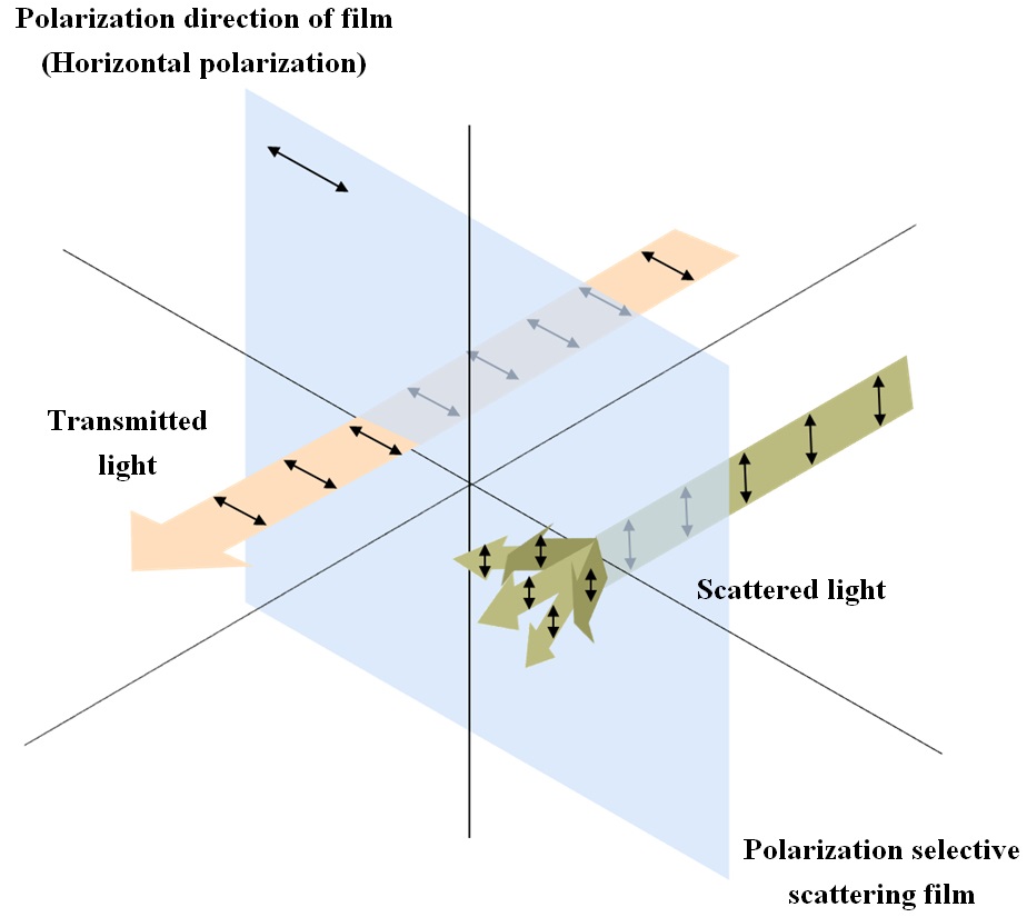
The polarization selective scattering film used in the proposed system has the scattering characteristics according to the polarization direction. The schematic diagram of the polarization selective scattering film is shown in Fig. 1. We assumed that the polarization direction of the polarization selective scattering film is the horizontal direction. If the polarization direction of the incident light is composed of only the horizontal component, the light will be transmitted through the film without any changes. However when the polarization direction of the incident light is composed of only the vertical component, the light should be scattered by the film.
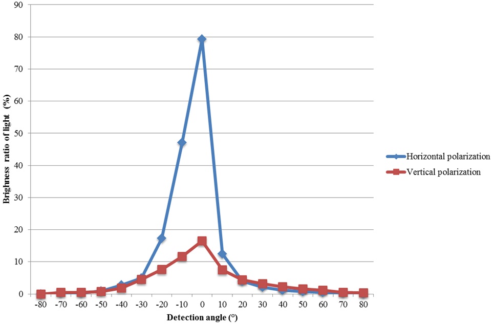
The scattering characteristic of the polarization selective scattering film can be investigated through the experiment, which is the measurement of the brightness of the light passed through the film. When the linearly polarized light which has only the horizontal or only the vertical polarization components has passed through the film, the brightness of the light is measured behind the film at a different angle from the optical axis. Fig. 2 shows the brightness of the light as a function of the detection angle. The standard brightness of the light is the brightness of the incident light on the film. When the horizontally polarized light enters the film, the brightness of the light on the optical axis is measured at about 80% compared to the standard
brightness and has decreased rapidly farther from the optical axis. Hence almost of the light whose polarization direction is parallel to that of the film is transmitted it straight. Otherwise, when the vertically polarized light enters the film, the brightness of the light on the optical axis is measured at about 17% compared to the standard brightness and has decreased slowly. It means that the incident light spreads out to a wide angle. That is, the light whose polarization direction is perpendicular to that of the film should be scattered.
In the proposed system, the conversion between the 2D mode and the 3D mode is controlled by the polarization modulator. On the 2D mode, the polarization modulator makes the polarization direction of the light be perpendicular to that of the polarization selective scattering film in
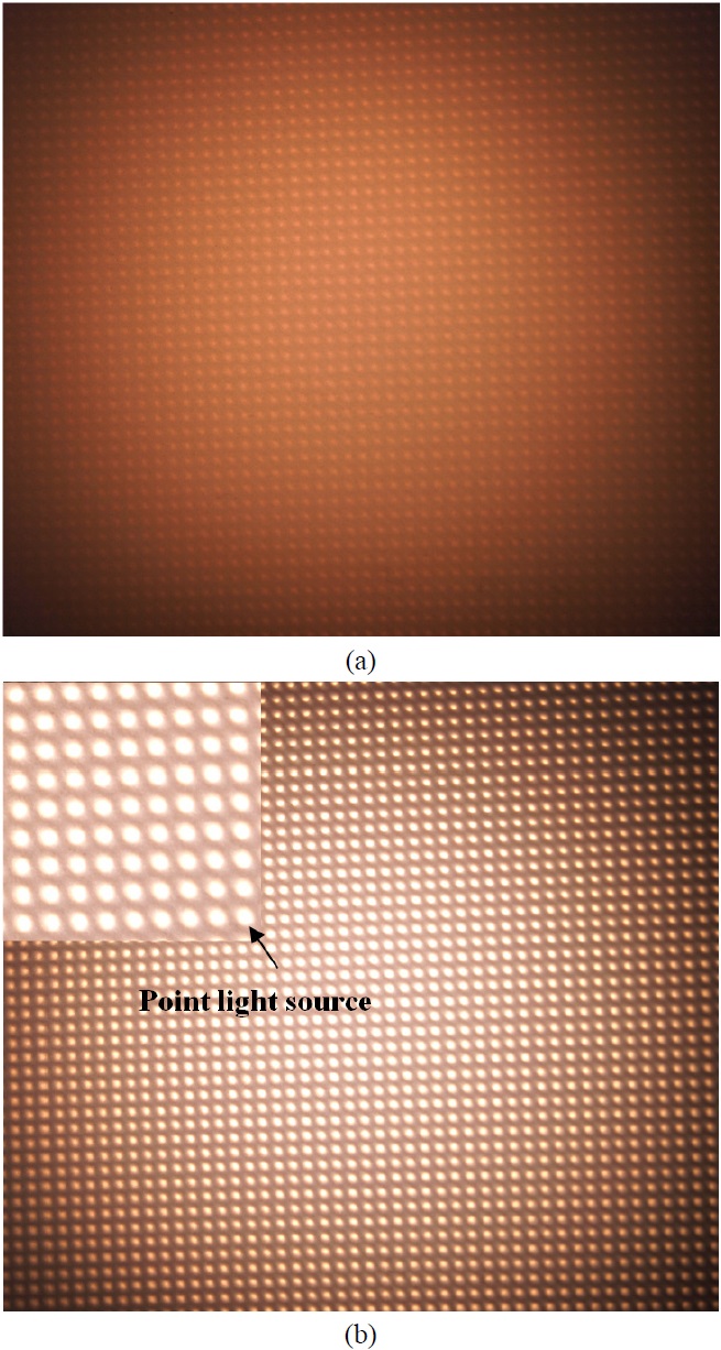
order to scatter the light by using the film. The elemental lens of the lens array refracts the scattered light but cannot make a clear focus because the incident angle of the scattered light is distributed randomly. Therefore, the normal plane light source is instrumented instead of the point light source. Fig. 3(a) shows the light distribution at the focal plane of the lens array on the 2D mode. The scattered light from the lens array is distributed on the whole SLM to display the 2D image and the resolution of the image depends on the specification of the SLM. Hence, the high resolution 2D image can be generated the same as on the 2D display device. The light, in Fig. 3(a), is the imperfect normal plane light source because of some defects such as the limited scattering performance of the polarization selective scattering film.
On the 3D mode, the polarization modulator makes the polarization direction of the collimated light be parallel to the polarization selective scattering film in order to transmit it through the film. Therefore, the collimated light can be focused on the focal point of each elemental lens of the lens array and the point light source array is implemented. Fig. 3(b) shows the point light source array generated at the focal point of the lens array. Each point light source should be assigned to the corresponding area in the SLM, which is not overlapped with each other since the distance between the lens array and the SLM is fixed to twice that of the focal length of the elemental lens of the lens array. The light from each point light source is modulated by the SLM and makes the intersection in the integrated space generate a 3D image. In the proposed system, the 3D image can be generated on the focused mode so that the image can be generated on the location on the real region, the virtual region, or both [13].
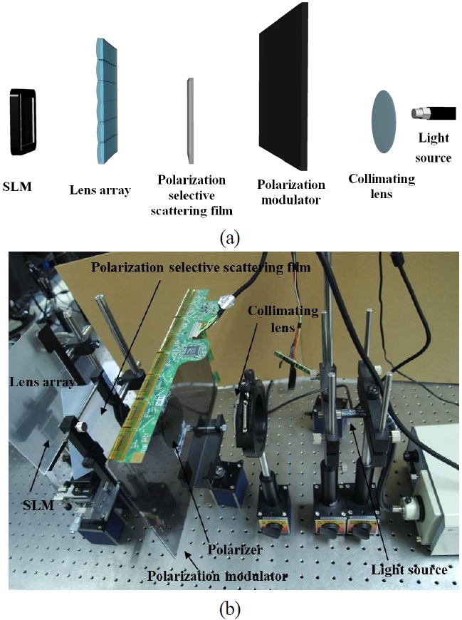
For verifying the principle of the proposed system, the fundamental experiments were performed. Fig. 4 explains the schematic diagram of the experimental setup. An illuminator and a collimating lens were used for acquiring the collimated light, which is important to make the point light source array. A normally white TN-LC panel removed back light source and the back-side polarizer was used as the polarization modulator. The size of the LC panel was 19 inch and the pixel size of the LC panel was about 0.32 mm × 0.32 mm. The Imajor™, the product of Teijin Dupont, was used as the polarization selective scattering film. A 100 × 100 plano-convex lens array on which each elemental lens is 1 mm × 1 mm size and 3.3 mm focal length was used. The pitch of the SLM was 0.036 mm pixel in both horizontal and vertical directions. Each elemental lens of the lens array corresponds with about 28 ⅹ 28 pixels on the SLM.
In experiments, two letters ’K’ and ’H’ were calculated for using the image on the 3D mode. The elemental images
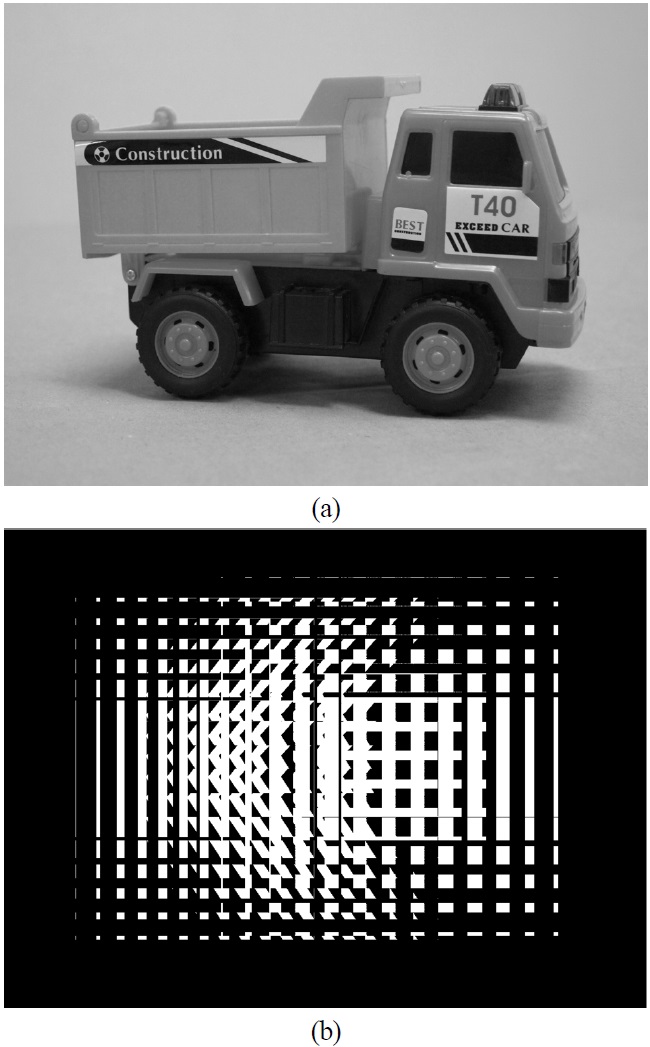
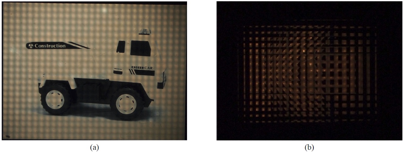
of the two letters were made by computer generation. The letter ’K’ was calculated to be the real image located at 30 mm in front of the point light source array. The letter ’H’ was calculated to be the virtual image located at 20 mm behind the point light source array. Fig. 5(a) and 5(b) show the ‘truck’ image and the computer generated elemental images of the two letters, respectively. To prove the proposed system, we compared two resultant images when the elemental images in Fig. 5(b) were displayed on the 2D mode and the 3D mode, respectively. The polarization modulator was operated by changing the black color whose gray level is 0, and white color whose gray level is 255.
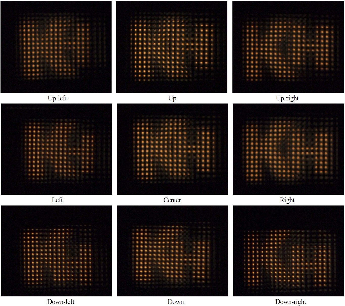
Figure 6 shows the resultant images on the 3D mode. The letters ‘K’ and ‘H’, which have different perspective, have been observed at the integrated space as different observation angles. The letters ‘K’ and ‘H’ were generated at the real and the virtual integrated field respectively. When the observer watched the 3D image moving along to the angle, the movement of the letter ‘K’ was opposite to that of the letter ‘H’ as shown in Fig. 6. Converting the 3D mode to the 2D mode, the image in Fig. 6 was changed to the image in Fig. 7(b) which is the elemental image displayed on the SLM.
Figure 7 shows the resultant images when the images
shown in Fig. 5 are displayed on the 2D mode. The resultant images could be observed clearly with the full resolution compared to the original images. It verifies that the characteristics of the image on the 2D mode depend on the parameters of the SLM.
However, the resultant image shown in Fig. 7(a) has problems that decrease the image quality: some uniform stains occur and the gray level is degraded. At first, some uniform stains result from the aberration of the elemental lens of the lens array. This problem can be alleviated by using a lens array of high quality. The degradation of the gray level is caused by the low quality of the monochromatic SLM and the low intensity of the light source. If the improved colored SLM and light source were adopted for the system, the full color image with the enhanced gray level could be presented.
Meanwhile, the conversion between the 2D mode and the 3D mode is implemented easily and quickly by modulating the gray level of the polarization modulator. Moreover, we can make the partial 3D image if the polarization direction of the incident light per unit pixel of
the polarization modulator can be controlled. The perfect collimated light can play an important role to make the partial 3D image and also increase the quality of the 3D image by making the perfect point light source. In the future, we will study the advanced 2D/3D convertible integral imaging system to improve the characteristics.
We propose the 2D/3D convertible integral imaging system using the polarization modulator and the polarization selective scattering film. The conversion between the 2D mode and the 3D mode is implemented by controlling the polarization direction of the light from the back light source using the polarization modulator. Although each monochromatic 2D and 3D image can be converted in the proposed system, it is possible to generate colorful 2D and 3D images using the colored SLM.
In the future, we will study the partial 3D image which can be generated by modulating the polarization direction of the light partially. We will expect the proposed system to be used in various applications for advanced 3D display market.