In order to deduce the difficulty of fixing the Ritchey-Chretien (R-C) dual reflective optical system and enhance the stability of the secondary mirror, a compact integral structure is presented here composed of two transmitting and two reflective aspheric surfaces. The four surfaces were manufactured from a single germanium lens and integrated together. The two reflective surfaces formed by coating the inner reflecting films were assembled in one lens. It makes the installation of the two mirrors easier and the structure of the secondary mirror more stable. A design of mid-wave infrared (MWIR) compact imaging system is presented with a spectral range chosen as 3.7-4.8 μm. The effective focal length is f=90 mm. The field of view (FOV) for the lens is 4.88°. It has good imaging capability with Modulation Transfer Function (MTF) of all field of view more than 0.55 close to the diffraction limitation. Outdoor experiments were carried out and it is shown that the integral catadioptric optical system performs well on imaging.
In recent years, the miniaturization and lightweight are paid more and more attention in a variety of optical system designs for aircraft and missiles [1]. Despite the small FOV, Ritchey-Chretien (R-C) dual reflective optical system has become the main choice for the domestic and foreign researchers because of its smaller, lighter structure and larger caliber [2-4]. However the assembly and the support mounting of the secondary mirror have been the main difficulties for Ritchey-Chretien dual reflective optical system: (1) the tolerance of R-C system is very sensitive which makes the assembly and adjustment difficult; (2) in order to reduce the obscuration of light caused by the brackets holding the secondary mirror, the size of the brackets usually is limited which leads to the instability of the secondary mirror [5]. The brackets will also be deformed when the missiles are accelerating forward. It decreases the image quality seriously, and reduces the accuracy of the guidance [4,5].
An integral catadioptric structure is adopted in this paper. The major and secondary mirrors were manufactured from a single lens so that there is no need to assemble and adjust them. The supporting structure of the secondary mirror will be removed which will not only increase the light irradiating the primary mirror, but also enhance the stability of imaging. The accuracy of the assembly and adjustment is converted to the process of manufacturing and now with the advanced single point diamond turning machine the machining accuracy can meet the requirements sufficiently. An optical design with the wavelength 3.7~4.8 μm was presented and 100% cold aperture efficiency was implemented. The imaging quality was close to the diffractive limitation.
II. R-C REFLECTIVE SYSTEM DESIGN
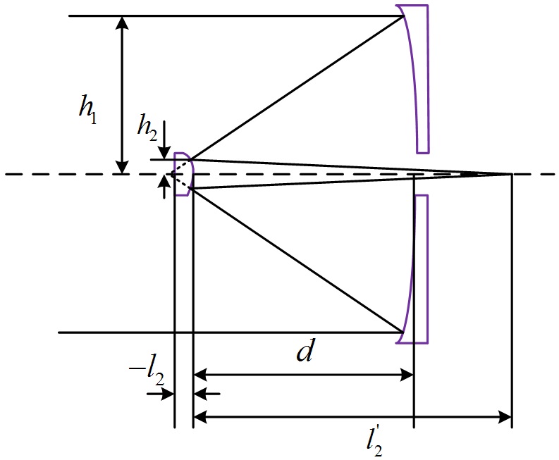
In order to design the integral catadioptric system, an initial R-C dual-reflective system ought to be designed first. Then the integral catadioptric can be achieved by adding material that transmits mid-infrared rays between the two mirrors. The final system can be gained after the optimization using Zemax or Code V. The structure of classical R-C reflective system is shown in Fig. 1. Changing the surface of primary mirror into hyperboloid can not only correct
the spherical and coma aberration, but also enlarge the field of the optical system.
The meanings of the symbols are demonstrated in Fig. 1. The distance of the target is infinite
There is no chromatic aberration in the R-C reflective system. When the monochromatic aberration is taken into consideration, the quadratic coefficient of the two mirrors can be derived in the aplanatic condition. The five monochromatic aberrations are spherical aberration, coma, astigmatism, field curvature, distortion.
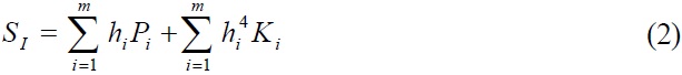
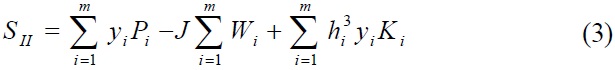
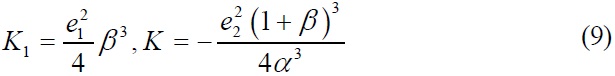
Where m is the total number of the surfaces. In R-C reflective system m equals 2, and
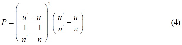
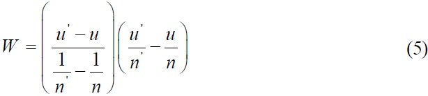
In the above equations

is the vertex curvature of the mirror. For computational advantage, we define the height of the light irradiating at the primary mirror as
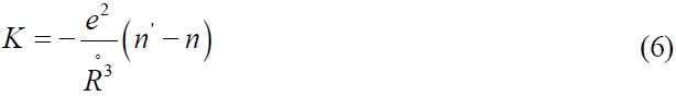
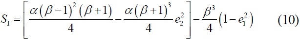
The equation (4)~(6) can be written as follows
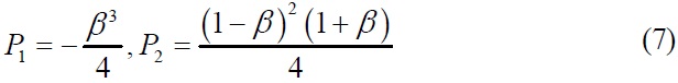
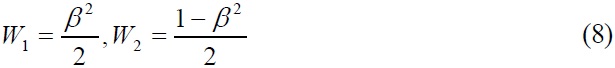
Then the spherical aberration, coma can be written as follows:
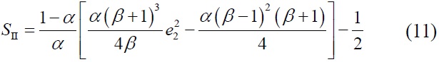
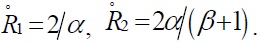
From the first order design and the initial structure parameters as
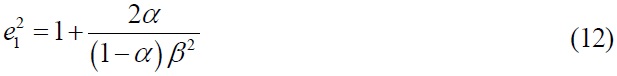
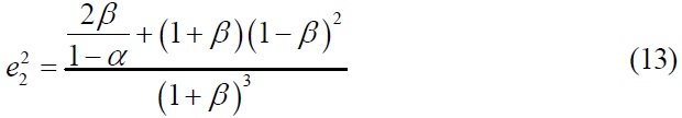
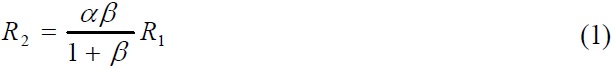
The initial structure of the R-C reflective system can be calculated by equation (1), (12), (13) for a given focal length of primary mirror, the obscuration ratio and the magnification of secondary mirror.
III. OPTICAL SYSTEM DESIGN AND ANALYSIS
3.1. Optical Design Requirements
The working brand of the optical system is 3.7~4.8 μm and the center wavelength is 4.2 μm. The medium wave detector is J-T refrigeration type, 320×256 array plane and the pixel size is 30 μm. The efficiency focal length of the system is 90 mm. F number is 1.86.
The field of view (FOV) can be calculated from equation (14) and (15)
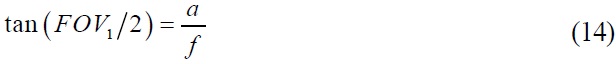
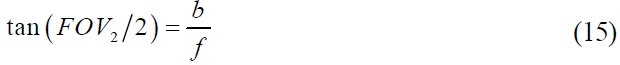
Where
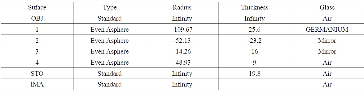
[TABLE 1.] Lens data from ZEMAX (unit: thickness/radius in mm.)

Lens data from ZEMAX (unit: thickness/radius in mm.)
full field of view.
The center obscuration is less than 40%. In order to resist the stray light irradiation, the cold aperture efficiency should be 100%. The full field energy in a pixel should be more than 80%.
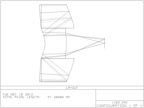
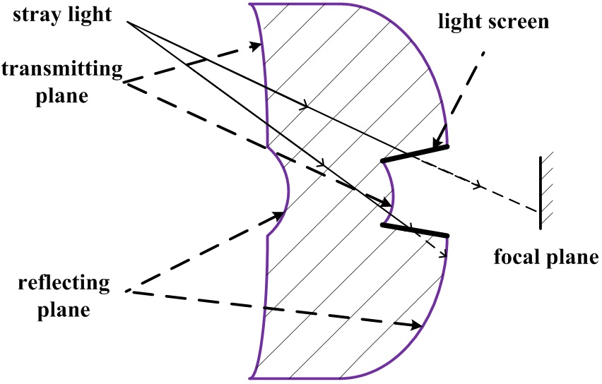
After optimizing the system for several times using Zemax-EE, an integral catadioptric system with a total length of 47 mm was realized as shown in Fig. 2. The system is made of four parts and the structure of the major part is shown in Fig. 3. In the front surface there are the incidence surface and the secondary mirror. In the rear surface there are the emergent surface and the primary mirror. The lens data is shown in Table 1 from ZEMAX lens data format.
The first surface of the lens is a concave surface which can effectively reduce the angle when light irradiates at the primary mirror. So this surface can not only decrease the off axis aberration of the system, especially spherical aberration and coma, but also enlarge the FOV of the optical system.
The fourth surface of the lens is convex. It can provide certain positive focal power which will decrease the power caused by the two mirrors. In this situation the redistribution of the power can reduce the aberration of the system. How to resist stray light is an important problem needed to be concerned in the reflective system [8]. In the design, the
emergent surface is placed between the two mirrors, which can shorten the length of the system and make it more compact. Secondly the circumference formed between the primary mirror and the emergent surface can work as a light screen by blacking. The stray light from other FOV will be restricted, for instance the light irradiating at the primary mirror or directly at the focal plane of the detector as shown in Fig. 3.
Due to the large field of view, a lot of off-axis aberration is induced. The two transmission and two reflective surfaces are all high order aspherical surfaces used to correct the aberration when we finished the optimization at last. The whole lens is made of germanium which is easy for manufacturing. The surface sag is shown as equation (16)
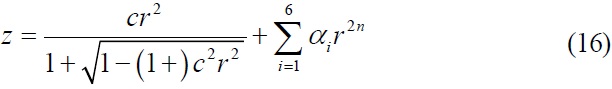
Where c is the curvature (the reciprocal of the radius), r is the radial coordinate in lens unit, k is the conic constant, and
The aperture stop is placed at 19.8 mm from the image plane and the diameter of exit pupil is set 10.6 mm to make the cold aperture efficiency reach 100%.
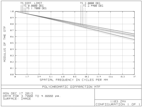
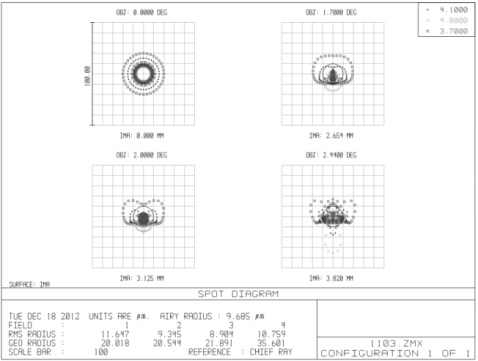
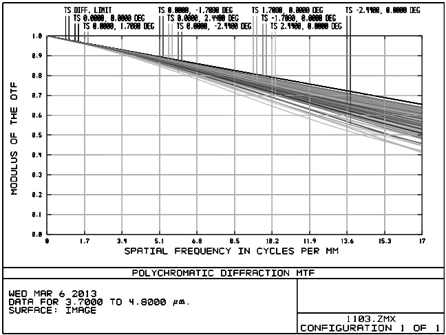
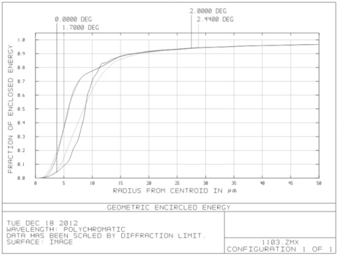
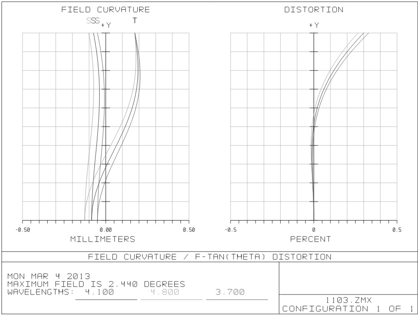
The optical transfer function, spot diagram and energy encircle curve were shown in Figure 4, Figure 5 and Figure 6, wherein the optical transfer function reached 0.55 close to the diffraction limit at the Nyquist frequency (16.67 lines per millimeter) and the geometry of the spot size was less than 35 μm. The full field energy in a pixel was more than 95%. Due to the wide FOV of the system, distortion is needed to be considered as shown in Fig. 7. The maximum distortion is less than 0.5% which can be ignored. The optical system presented an excellent image quality.
[TABLE 2.] Even aspheric parameters
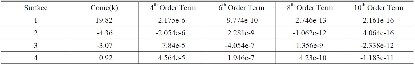
Even aspheric parameters
[TABLE 3.] Optical tolerances for manufacturing
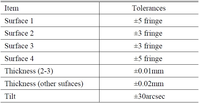
Optical tolerances for manufacturing
3.3. The Optical Tolerances for Manufacturing
Just the manufacturing errors concerned, the optical tolerances are shown in Table 3. The thickness between the two mirrors is found to be very sensitive by changing the thickness manually and the tolerance is set ±0.01 mm. For the other thickness, since they are insensitive, the tolerance is set ±0.02 mm. Since all the manufacturing was completed in the advanced single point diamond turning machine which can provide very high precision at a scale of 10nm, we can conclude that the tolerances are loose and reasonable. With Monte Carlo calculations the MTF will be changed 0.18 for 17lp/mm at most in the Zemax program as shown in Fig. 8.
3.4. Experiments and Results Analysis
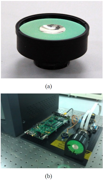
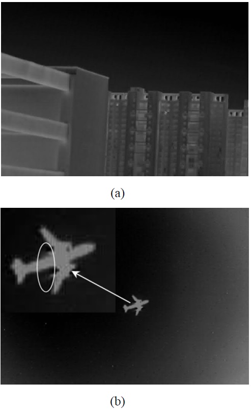
The integral catadioptric lens was finally manufactured using the advanced single point diamond turning machine and assembled with mechanical parts as shown in Fig. 9 (a). The set up of the optical experiment platform of the MWIR imaging system goes as shown in Fig. 9 (b). Two outdoor experiments were carried out to test the performance of the imaging system at night. In Fig. 10 (a) the targets are some buildings. From the image we can identify the edge of the building clearly. In Fig. 10 (b) an air bus was chosen to image. The configuration was distinct and even the heated air out of the engines can be seen from the
image. These experiments proved that the integral catadioptric system had an excellent performance for MWIR imaging.
This paper presented an MWIR integral catadioptric imaging system. The focal length of the system was 90 mm manufactured from a single germanium lens. The cold aperture efficiency was 100%. This kind of system was easier to assemble and adjust for the secondary mirror is integrated in the lens, providing a very compact structure and making the fixing easier. The circumference formed between the primary mirror and the emergent surface efficiently reduces the stray light and enhances the image quality in the focal plane. With spectral range 3.7-4.8 μm, the system transfer function achieved at 0.55 in 17l p/mm which is close to the diffraction limit. Outdoor imaging experiments were carried out with real integral catadioptric system which provided a good imaging quality.