Fiber-based, passively mode-locked (ML) laser sources have become important tools for a variety of scientific and engineering applications [1-7] because of their simplicity and compactness in obtaining a broad range of operation in terms of pulsewidth (fs to ps) as well as pulse repetition rate (kHz to GHz). Since they are primarily based on fiber laser technology, they also allow for excellent power scalability, large spectral bandwidth, and good spatial mode quality [8]. In fact, passive mode-locking (ML) is an all-optical technique that relies on the intensity-dependent cavity loss mechanism via the interaction of intensity fluctuations and nonlinearities of the laser cavity medium without having an external control for the signal [9]. Over the last decades, various passive ML mechanisms or devices, which include nonlinear polarization evolution [10-12], nonlinear amplifier loop mirrors [13,14], semiconductor saturable absorber mirrors (SESAMs) [15-37], more recently carbon nanotubes (CNTs) [38,39], graphene [40-42], etc have been introduced to fiber lasers. The first two methods rely on the “virtual” saturable absorbers via the Kerr nonlinearity of fiber combined with a polarizer. While these types of saturable absorbers present fast recovery times which allow for the formation of sub-hundred fs pulses [9], such methods in general do not readily offer self-starting ML and long-term stability to the system. On the other hand, the inclusion of “real” saturable absorbers, such as the last three devices, can radically enhance the cavity loss modulation in the cavity, thereby leading to self-starting ML and also providing high stability to the system [16].
Among the three real saturable absorbers, CNT- and graphene-based saturable absorbers have received a lot of attention over the recent years [38-42] since they can be relatively easily fabricated and integrated with optical fibers [39]. Furthermore, CNT-based saturable absorbers can allow for the formation of very short pulses because of their fast recovery times [39], and on the other hand graphene-based saturable absorbers offer a very broad spectral range of operation [39]. While they have great potential to be used for passively ML fiber lasers (PMLFLs), their development is still in the early stages [40-42]. In contrast, SESAMs have already been proven as commercial products, offering standardized performance as a saturable absorber with excellent long-term reliability [16]. In this light, SESAMs are absolutely suitable for use in master-oscillator lasers, which invariably require superior long-term reliability in the first place.
Here, we present a brief review of the recent development of PMLFLs based on SESAMs, their fundamental characteristics, and the detailed characterization of a SESAM-based wavelengthtunable PMLFL that can generate optical pulses of fs to ps, building on our previous investigations [36,37]. In particular, we analyze the formation of the pulses with respect to the filter bandwidth as well as the tunability across the 1.5-μm spectral range. For this, a sigma-cavity configuration is investigated for two different types of tunable filters. The excellent stability of the developed PMLFL eventually enables it to be used as a master oscillator for a poweramplifier source based on a large-core erbium-doped fiber (EDF), generating picosecond pulses of >10-kW peak-power and >100-nJ pulse-energy, which should be very useful for second-harmonic generation or supercontinuum generation, for example.
II. REVIEW OF SESAM AND SESAM-BASED PMLFLS
Since the first development of a SESAM in 1992 [15], it has become an essential intra-cavity component for passive ML lasers [14,15]. One of the reasons for their successful, commercial growth relies on the fact that their optical properties can be engineered to be fitted for a broad range of laser cavity designs [15-37]. While SESAMs were initially utilized to resolve the Q-switching instability problems in ML solid-state lasers suffering from excessively long upperstate lifetimes [15,43], their uses in PMLFLs have also offered an excellent route forward to realizing stable, selfstarting ML mechanisms [18]. Hence, the progress in SESAM technology has paved the way for building compact and stable ultrashort-pulsed lasers in PMLFLs as well as in bulk-type solid-state lasers [15-37].
In general, semiconductor materials are good saturable absorbers because of the interplay of carriers between the valence and conduction bands: For instance, when there is incoming light to a semiconductor material, it will excite carriers (electrons or holes) from the valence band to the conduction band [16] if it has sufficient photon energy exceeding the bandgap energy of the semiconductor material, which will, in fact, result in the absorption of the incoming light. The absorption rate may remain unchanged if the intensity of the light (photon intensity) is sufficiently low. However, if the photon intensity is high, the absorption will be saturated since the carriers in the valence band are temporarily depleted until the excited carriers are released back into the valence band from the conduction band, thereby leading to a temporal reduction of the net loss of the device to the incoming light. Since these devices are usually integrated with mirror structures, in such cases the reflectivity of the device will increase within the relaxation time of the semiconductor material as its optical loss reduces at high photon intensities. These types of devices based on semiconductor materials are known as SESAMs [16,17].
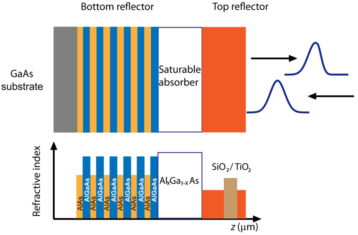
A typical structure of a SESAM is shown in Fig. 1. A bottom Bragg reflector is formed by a group of N-pair quarterwaveplates of GaAs/AlAs grown on a semiconductor substrate GaAs, for example [15]. The Bragg wavelength of the reflector is primarily determined by the operating wavelength of the target laser. This mirror structure is then followed by a semiconductor saturable absorber and a secondary top reflector. The secondary top reflector can be formed either by the simple saturable absorber/air interface or by a Bragg reflector. It should be noted that the optical pulse reflected by the SESAM will undergo a significant decrease in its leading edge because the saturable absorber initially keeps giving rise to high loss until the loss is saturated by the central part of the optical pulse of high intensity. Consequently, optical pulses will become steeper and steeper while being repeatedly reflected by the SESAM, which, in fact, functions as a high-intensity-pass shutter in a laser cavity.
In general, the output spectrum of a fiber laser can be formed of many longitudinal modes, i.e., many spectral components spaced by the fundamental repetition rate that is the inverse of the cavity round-trip time. In a homogeneously- broadened gain medium like an EDF, such modes compete for gain resources within the finite gain bandwidth given in the cavity, and only the mode which sees the highest net gain will dominate over the other modes. For the case in which the longitudinal modes are independent and random in phase, the instantaneous amplitude of the laser output will also oscillate randomly in the time domain, thereby only being able to emit steady average output power. However, when the phases of all the longitudinal modes
are fixed to a constant value, the laser output will emit a pulse train oscillating at the fundamental repetition rate or its higher-order harmonics [9]. In order to have such a regularly oscillating pulse train, i.e. to lock the longitudinal modes, there must be a mechanism to initiate the intensity fluctuation and clean up the undesirable emissions between the pulse intervals. This can be achieved by an active method, e.g. by an electro-optic modulator or by a passive method, e.g., by a saturable absorber like a SESAM. As described earlier, the fast saturation and recovery of the loss mechanism obtained from a SESAM invariably favors regularly oscillating pulses formed of phase-locked longitudinal modes of the cavity. That is, the use of a SESAM in a homogeneouslybroadened laser cavity can readily lead to passive ML.
As described above, the properties of SESAMs can be tuned and engineered for many particular purposes of target lasers, and thus, there are a variety of choices for them. Due to the dramatic growth in semiconductor technology, SESAMs of various characteristics are mostly commercially available [44]. Thus, it conversely becomes the first and foremost task to choose a correct SESAM design in order to achieve a good laser performance or to avoid Q-switching instabilities. (The latter is a common issue for lasers having gain media of excessively long upper-state lifetimes [17].) For example, if modulation instabilities are not present in the laser cavity, such as in stretched-pulse laser cavities [20], a SESAM with high modulation depth (


where
Since the first GaAs-based SESAM devices were developed for 800-nm radiation [16], various semiconductor materials and compositions have been developed for other infrared ranges [18-37]: For 0.9-1-μm radiation, SESAMs are mostly fabricated in a form of an InGaAs multiple-quantumwell structure grown on top of a GaAs/AlAs Bragg mirror [23,30]. With such devices ML lasers based on neodymium (Nd)- and ytterbium (Yb)-doped fibers have been demonstrated [23,30]. Other types SESAMs based on GaInNAs structures for the 1-μm and 1.3-μm wavelength regions have also shown good performance for ML-lasers [22,26,32]. These SESAMs utilize a GaInNAs-based structure grown on top of a GaAs/AlAs Bragg mirror. With such a device, a ML laser based on a bismuth (Bi)-doped fiber has been demonstrated [32]. For radiations around 1.5 μm or above, InP-based [19,25,33] SESAMs and GaAs-based diluted nitride [27] SESAMs are commonly used: An InGaAs/InP Bragg mirror with an absorber made of InGaAs quantum wells has been used to generate 190-fs pulses from a thulium (Tm)-doped fiber laser operating at ~2 μm [33]. More recently, a ML Tm/Holmium (Ho)-doped fiber laser has been built with help of a SESAM where the absorber material was formed of a group of GaInSb quantum wells grown on top of an AlAsSb-GaSb Bragg mirror [24].
Leveraged by such rapid progress in the SESAM technology, there have been dramatic advances in SESAM-based PMLFLs operating at ~1.5 μm. This spectral range (which will be discussed throughout this paper) is of great interest because of its inherent “eye-safe” nature together with good transmission in both silica and air. Consequently, such PMLFLs have been investigated for many novel scientific and engineering applications, such as free-space communication, range finding, LIDAR, and medicine [1-6], besides the optical fiber telecommunications. Thus, a variety of compact and self-starting PMLFLs in femtosecond and picosecond regimes have been demonstrated: For example, in the femtosecond regime, 320-fs soliton-like pulses with 40-pJ pulse energy have been generated in a simple linear cavity with an InGaAsP saturable absorber [19], while sub-500-fs pulses with repetition rates as high as 300 MHz have been generated with an InGaAs/InP saturable absorber [34], which could also operate at higher harmonics by increasing the repetition rate up to 2 GHz. In the picosecond regime, saturable absorbers based on GaInNAs/GaAs have been used to generate 7.6-ps noise-like pulses from an Er/Yb-doped fiber [35] and 1.2-ps soliton-like pulses from an EDF [27].
In addition, saturable absorbers have also been investigated for various other purposes: For example, an inclusion of linear loss elements in cavity combined with an InGaAsP-based saturable absorber could avoid multiple-pulse formation at high pump powers [18]. Hybrid configurations incorporating a pair of fast and slow saturable absorbers have been proposed to provide a reliable self-starting ML mechanism [21], where pulses with 250-pJ pulse energy were generated without having multiple-pulse breakup at high pump powers. SESAMs have also been used for pulse shaping in fiber lasers operating at fundamental repetition rates above 2 GHz [28].
Hence, it has become clear that SESAMs have vitalized PMLFLs with novel characteristics as well as offering robust reliability, thereby having now been proven as a mature technology [16]. Here we discuss in the following sections the detailed configurations and characteristics of a SESAM-based, wavelength-tunable PMLFL.
III. CAVITY CONFIGURATIONS AND SESAM CHARACTERISTICS
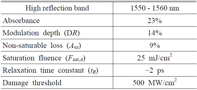
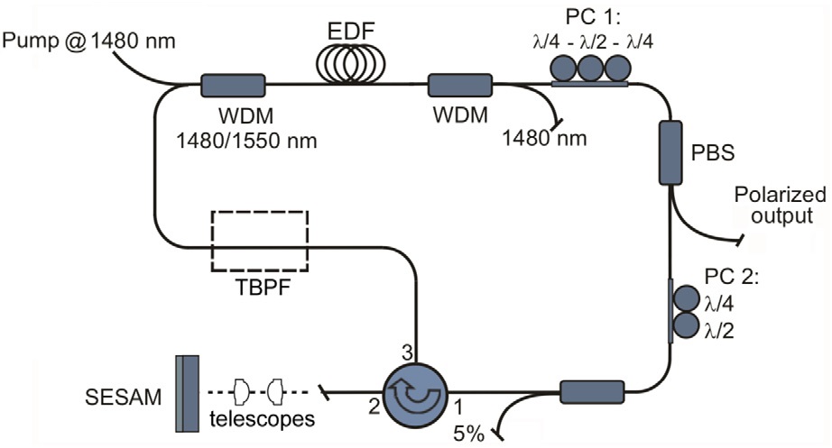
A sigma configuration proposed for our PMLFL is shown in Fig. 2. The laser consists of 2 m of an EDF (Fibercore), which has a small-signal absorption rate of ~37 dB/m at 1530 nm and is pumped by a single-mode laser diode (LD) of a total power of 140 mW at 1480 nm through a 1480/1550 wavelength-division-multiplexed (WDM) coupler. A second 1480/1550 WDM coupler is spliced to the other end of the EDF in order to remove the unabsorbed pump light from the cavity. Two sets of polarization controllers, PC1 and PC2, are inserted before and after a fiberized polarization beam splitter (PBS) to introduce an appropriate phase bias for locking the longitudinal modes of the ring cavity as well as to adjust the output coupling ratio through the PBS. PC1 is comprised of three waveplates (a quarterwaveplate, a half-waveplate, and a quarter-waveplate), while PC2 is of only two waveplates (a quarter-wave-plate and a half-waveplate). A 95:5 tap coupler is spliced to PC2 to monitor the intra-cavity signal, which is followed by a 3-port circulator. The fiber end of port-2 of the circulator is angle-cleaved, and its output signal is collimated and launched onto a SESAM (BATOP Optoelectronics, see Table 1 for
[TABLE 1.] SESAM specifications

SESAM specifications
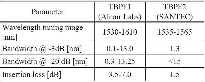
[TABLE 2.] Specifications of the two TBPFs used in the PMLFL

Specifications of the two TBPFs used in the PMLFL
details) through a pair of aspheric lenses, which facilitates adjusting the incident pulse fluence onto the SESAM via varying its illuminated area. Finally, to close the sigma cavity, the output port of the circulator is spliced to the input port of the first 1480/1550 WDM through a reconfigurable section which may or may not include a fiberized tunable band-pass filter (TBPF). For the fiberized TBPF we investigate two different types: One is a novel type of tunable filter that can also offer a bandwidth-adjustable function (TBPF1: Alnair Labs, see Table 2 for details). The other is a low-loss fiberized optical tunable filter (TBPF2: SANTEC, see Table 2 for details) with a fixed filter bandwidth (
Thus, the total cavity length can be 10.92 m (without a TBPF), 15.54 m (with TBPF1), or 15.06 m (with TBPF2), unless stated otherwise. We estimate the corresponding average group velocity dispersion (GVD) parameter of the resultant cavity to be
4.1. Femtosecond-pulsed Regime
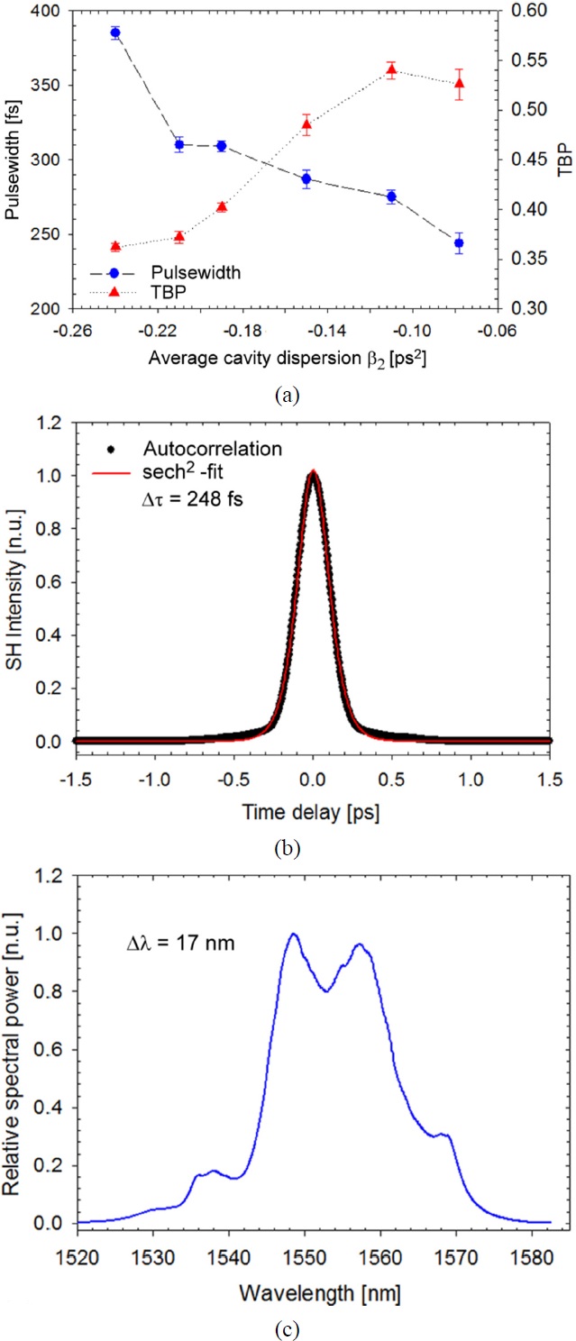
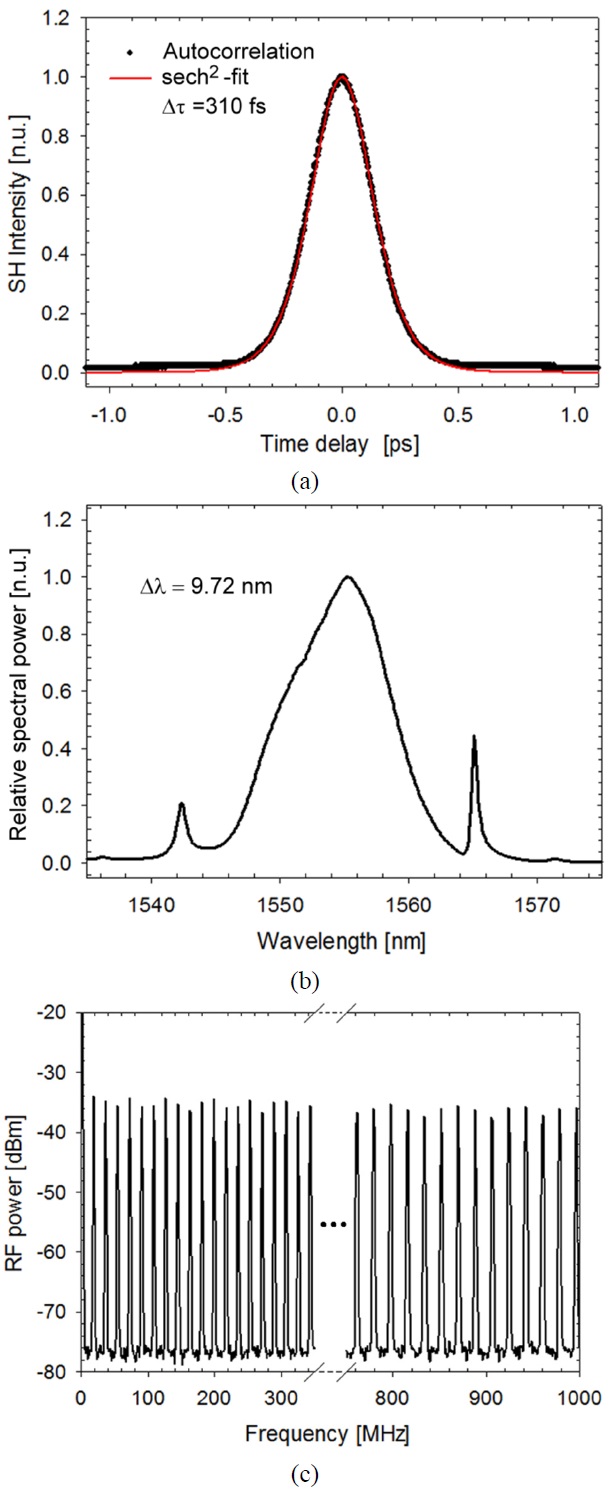
We first characterized the laser system without incorporating a TBPF. That is, the output port of the circulator was directly spliced to the input port of the first 1480/1550 WDM though a standard single-mode fiber (SMF28, Corning). In this configuration, the laser presented stable, self-starting ML pulses centered at 1556 nm circulating at the fundamental cavity frequency of 18.30 MHz for the pump power (
According to the soliton area theorem [3], the pulse energy and pulsewidth are related to the average GVD and nonlinearity of the cavity as follows:
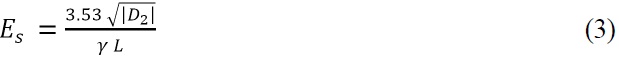

where
fiber section (SMF28) of the cavity. The pulsewidth varied from 248 to 385 fs, depending on the average cavity dispersion. In particular, a minimum pulsewidth of 248 fs (FWHM) with a TBP of 0.526 was obtained for
decreased. Further reduction of the cavity length was limited by the available length of the passive fiber section in the cavity. In addition, in Fig. 4(c) one can see that when
4.2. Picosecond-pulsed Regime with TBPFs
We decided to insert a TBPF into the cavity in order to make the PMLFL operate in a wavelength-tunable, picosecond regime, for which we utilized the two TBPFs described in Sec. III. To analyze the influence of the filter bandwidth on the laser characteristics, we firstly investigated the use of TBPF1 because its bandwidth was adjustable while its center wavelength was tuned.
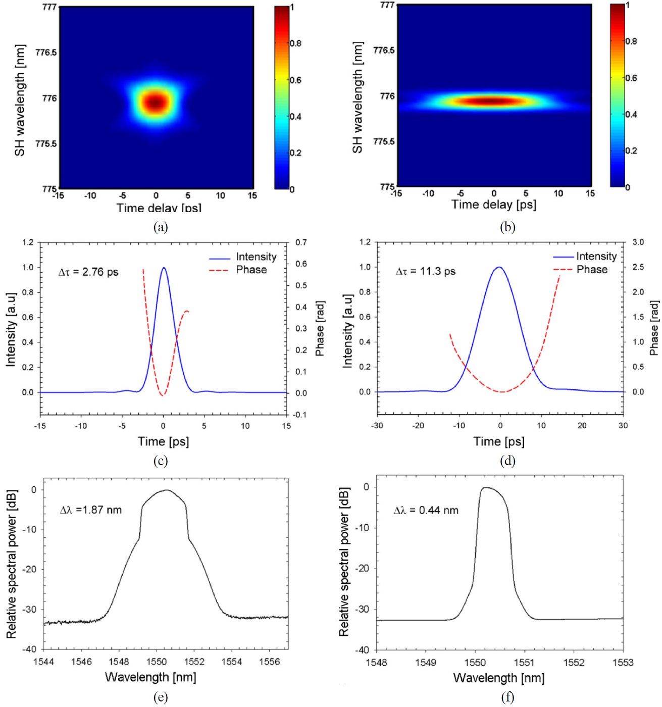
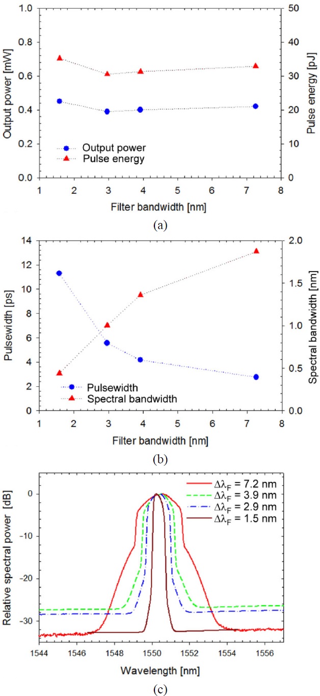
We initially characterized the PMLFL, adjusting the filter bandwidth from 7.2 nm to 1.5 nm while keeping the filter center wavelength fixed at 1550 nm. Within this bandwidth range we could obtain stable ML picosecond pulses; however, beyond this range we could see that ML pulses went slightly unstable. For the filter bandwidth of TBPF1 of 7.2 nm, the PMLFL generated stable, self-starting fundamental ML pulses of 2.76-ps pulsewidth, circulating at 12.87 MHz, for which pump power was set to ~30 mW. This pulse regime remained completely locked even when the bandwidth of the filter was narrowed down to 1.5 nm, with which the pulsewidth was broadened to 11.30 ps.
Figure 5 shows the experimentally measured FROG traces, the retrieved pulse intensities and phases, and the optical spectra when the filter bandwidth was set to 7.2 nm and 1.5 nm, respectively. In this regime, the TBP was maintained as high as 0.64 to 0.62 for
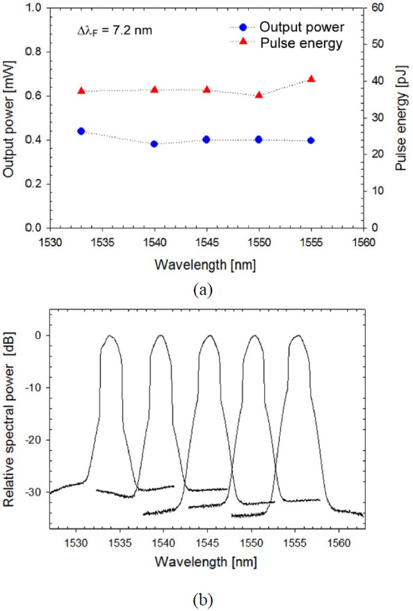
The measured average output powers together with the calculated pulse energies, and measured pulsewidth together with the spectral bandwidth are shown in Fig. 6(a) and Fig. 6(b), respectively, as a function of the bandwidth of TBPF1. The corresponding optical spectra of these measurements are shown in Fig. 6(c), for which the center wavelength of TBPF1 was fixed at 1550 nm as in Fig. 5. It is also worth mentioning that the PMLFL could also generate pulses of a pulsewidth as short as ~1.3 ps when the bandwidth of TBPF1 was set to the maximum filter bandwidth of ~13 nm. However, in this case, continuous wavelength tuning beyond 1550 nm was hardly achieved, which was possibly attributed to the fact that the net gain spectrum of the laser cavity, including the gain of EDF and the loss of TBPF1, was not flat and wide enough to allow for broadband tuning in such a condition.
As a result, we found that the broadest filter bandwidth allowing for continuous wavelength tuning from 1533 nm
to 1555 nm was given by
Next, we investigated TBPF2 for the wavelength-tuning of the PMLFL in the picosecond regime. The high insertion loss (IL) of ~5 dB of TBPF1 eventually made it difficult to achieve continuous wavelength-tuning of the PMLFL while keeping the pump power fixed at a constant level. That is, we inconveniently had to adjust the pump power to stabilize
the ML pulses. Thus, we utilized TBPF2 that had a relatively low IL of ~1.5 dB with a sufficiently large tuning range from 1535 nm to 1565 nm although its bandwidth was fixed to ~1.3 nm.
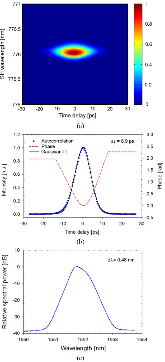
When TBPF2 was initially tuned at 1552 nm, self-starting, fundamental ML pulses were obtained with the pump power as low as ~23 mW thanks to the low IL of TBPF2 (see Sec. II). Fig. 8 represents the corresponding output
characteristics of the PMLFL, including the experimentally measured FROG trace of the output pulse, its retrieved intensity and phase, and its spectrum. In the given condition, the pulsewidth, spectral bandwidth, TBP were given by ~8.9 ps, ~0.48 nm, and 0.53, respectively. The retrieved phase information of the output pulse indicate that it was also linearly up-chirped similar to the case with TBPF1 (see Fig. 5). In this configuration, we could obtain excellent stability of the ML pulses. Actually, once they were self-started, their ML regime remained completely uninterrupted even with tuning of the TBPF2 throughout the whole tuning range of 1535 nm to 1560 nm. The pulsewidth of the PMLFL with TBPF2 (
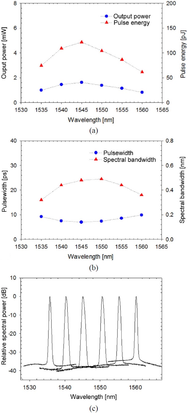
Figure 9 shows the pulse characteristics over the entire tuning range of the PMLFL from 1535 nm to 1560 nm, including its average output power, pulse energy, pulsewidth, spectral bandwidth, and tuned spectra. For this measurement, the pump power was fixed at ~23 mW. We emphasize that thanks to the reduced IL of TBPF2 (~1.5 dB), the average
output power was significantly improved to ~1 mW, and this configuration offered much better performance in terms of the pulse stability as well as tuning range, compared to the case with TBPF1.
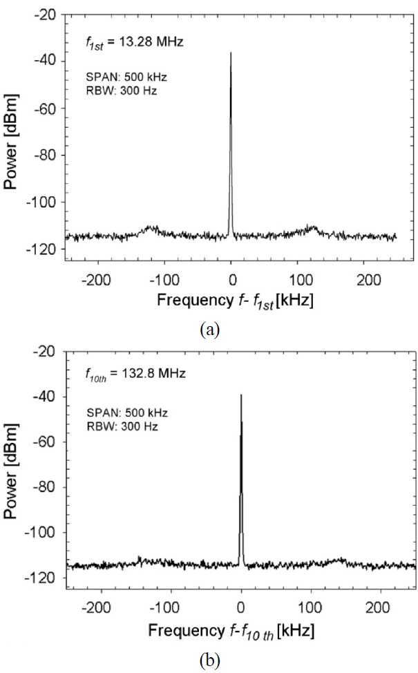
Here we further characterized this PMLFL, measuring its amplitude noise and timing jitter as follows: Fig. 10 represents its RF spectra measured at the fundamental cavity frequency of 13.28 MHz and at the 10th harmonic
frequency of 132.8 MHz, respectively, when the PMLFL was tuned at 1552 nm. Based on the RF spectra [48], we characterized the amplitude fluctuation of the PMLFL to be
0.08% [46]. This also highlights the high stability of the PMLFL, considering that no additional measure was implemented to stabilize the PMLFL system besides utilizing a SESAM [49,50].
Direct amplification of picosecond-pulses in a MOPA configuration:
As discussed above, a SESAM-based PMLFL could generate well-stabilized optical pulses in both femtosecond and picosecond regimes, which is absolutely suitable for use as a master oscillator to other laser systems. Here, we briefly discuss one application of the developed source to a large-core EDF-based MOPA system [37].
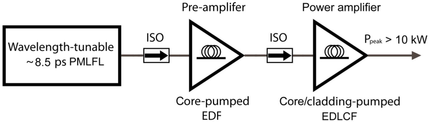
Figure 11 shows the MOPA system designed for generating wavelength-tunable picosecond pulses of >10-kW peak power. The system was seeded by the SESAM-based PMLFL with TBPF2 as described previously. It is noteworthy that the PC1 and PC2 were further adjusted in order to make the pulsewidth fixed at ~8.5 ps. Then, the output signal of the master-oscillator PMLFL was amplified up to ~31 mW in terms of average power by a pre-amplifier based on a
core-pumped EDF (Fibercore) with a length of 1.3 m. This pre-amplified signal was further amplified by a power amplifier comprising a 3.7-m Yb-free, double-clad erbium-doped large-core fiber (EDLCF, CorActive). We utilized a hybrid pumping scheme to pump this double-clad EDLCF by using a multimode LD of ~7.2 W at 976 nm and a single-mode Raman fiber laser of ~950 mW at 1480 nm. (See Ref. [37] for more details.)
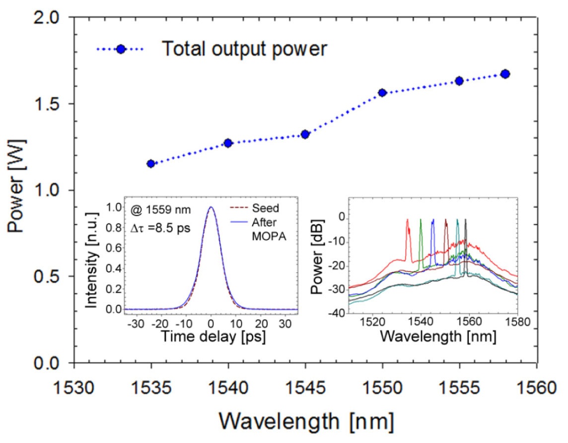
Figure 12 shows the average output power measured over the entire tuning range, together with a typical autocorrelation trace of the output pulse at 1559 nm and its tuned spectra in the insets. The average output power was increased up to 1.67 W at 1559 nm while it was reduced to 1.15 W at 1535 nm. Although the amplified spontaneous emission (ASE) in the power-amplifier stage was a limiting factor to the signal amplification for wavelengths shorter than 1550 nm [37], we emphasize that the stability and reliability of the master-oscillator PMLFL was well demonstrated over the entire tuning range of 1535 nm to 1559 nm. In particular, the MOPA system could generate stable pulses with the maximum peak power of ~12.6 kW and the pulse energy of ~107 nJ when tuned at 1559 nm.
[TABLE 3.] Summary of the laser characteristics described in Section IV
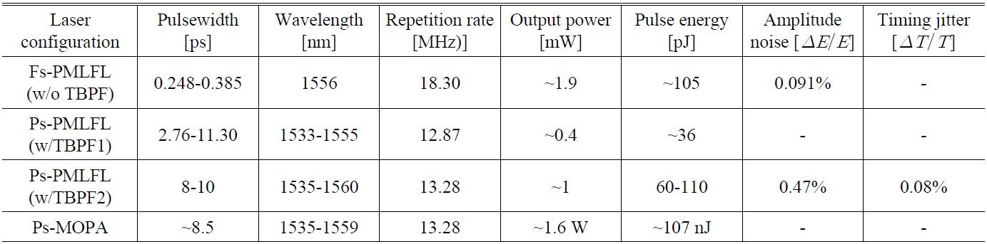
Summary of the laser characteristics described in Section IV
We have discussed SESAM-based PMLFLs, paying particular attention to an EDF-based system that was wavelength-tunable in the 1.5-μm spectral range. The proposed simple and compact laser cavity enabled the PMLFL to operate either in a femtosecond regime or in a wavelength-tunable picosecond regime, both of which offered self-starting, stable CW ML pulses with no Q-switching instabilities. In a free-running cavity configuration without incorporating a TBPF, we could obtain stable 248-385 fs pulses, and the amplitude fluctuation was as low as ~0.091% for 310-fs pulses. In TBPF-inserted cavity configurations, the IL of the TBPF had a significant influence on the overall stability and tuning range of the PMLFL: With TBPF1 (IL = ~5 dB), we could obtain a stable tuning range of 1533 nm to 1555 nm for

![Schematic of a semiconductor saturable absorber mirror [15].](http://oak.go.kr/repository/journal/12186/E1OSAB_2013_v17n2_117_f001.jpg)