검색 전체 메뉴
PDF
맨 위로
OA 학술지
Frequency Tuning Characteristics of a THz-wave Parametric Oscillator
  • 비영리 CC BY-NC
  • 비영리 CC BY-NC
ABSTRACT
Frequency Tuning Characteristics of a THz-wave Parametric Oscillator
KEYWORD
THz-wave parametric oscillator , Noncollinear phase-matching , Quasi-phase-matching , Tuning THz-wave
  • I. INTRODUCTION

    Applications of the THz-wave in spectrum analysis [1,2], biology and medicine [3,4], communications [5], security technologies [6] and quality control [7] have raised much interest in terahertz photonics. Unfortunately, lack of practical terahertz sources restricts the applications of the THz-wave. Until there are more practical sources available, the full potential of terahertz radiation will remain, to a great extent, unrealized. Due to the interest in exploiting this region there are many schemes proposed on source technologies over the last fifteen years or so. [8-11] Among many electronic and optical methods for the THz-wave generation, the THz-wave parametric oscillator (TPO) exhibits many advantages, such as compactness, narrow linewidth, coherent, wide tunable range, high-power output and room temperature operation [9]. For efficient generation of the THz-wave, MgO:LiNbO3 is one of the most suitable crystals due to its large nonlinear coefficient and its wide transparency range. [12] In the TPO both noncollinear phasematching configuration and quasi-phase-matching configuration can perform well. The tuned THz-wave can be realized by varying phase-matching angle, pump wavelength and operation temperature.

    In this letter, the frequency tuning characteristics of the THz-wave by changing the pump wavelength, the phasematching angle, the operation temperature and the poling period of the PPLN crystal are investigated. Parametric gain coefficients of the THz-wave under different working temperatures are analyzed.

    II. PHASE-MATCHING SCHEMES

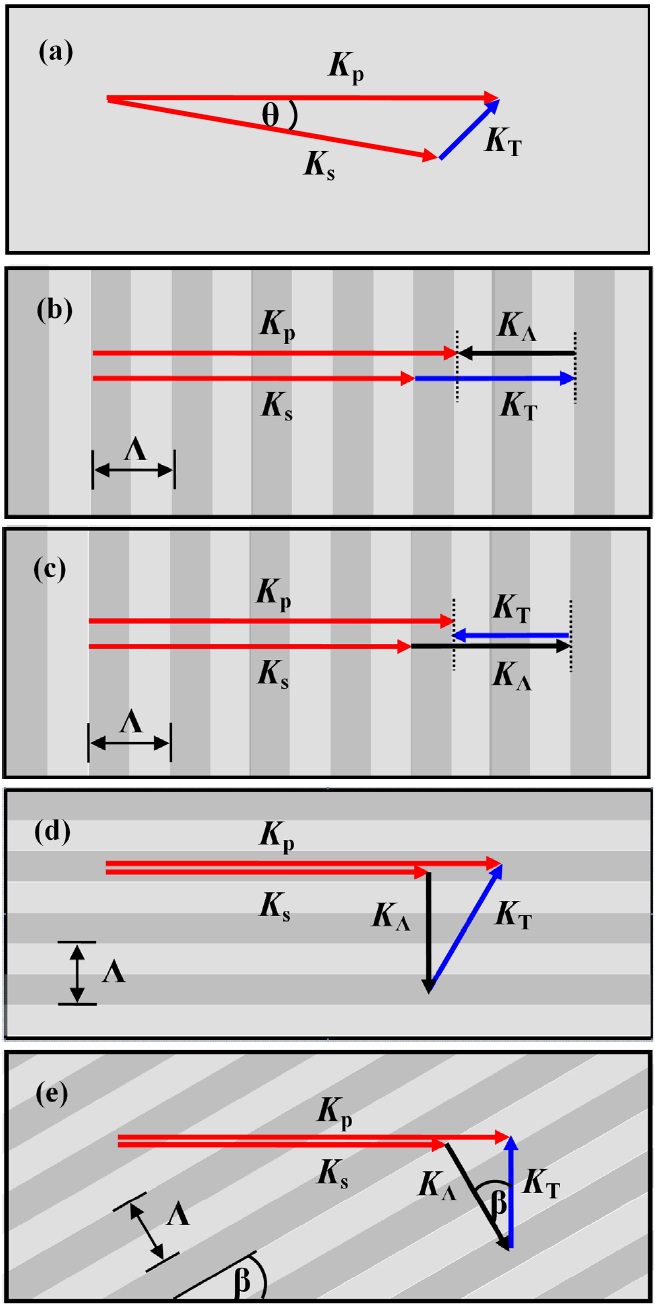
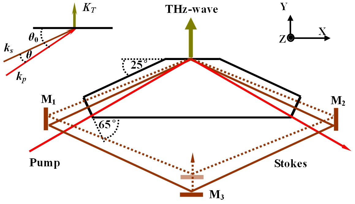
    The phase-matching in the TPO is necessary to avoid destructive interference of the Stokes wave and the THz-wave which are produced by the stimulated Raman scattering. For a LiNbO3 crystal the refractive index in the terahertz range is around 5, as compared to 2 in the near infrared, so birefringence phase-matching is not applicable in this case. One method that has been used by several groups is noncollinear phase-matching based on the bulk LiNbO3 crystal as the nonlinear gain medium, in which the pump wave, the Stokes wave and the THz-wave are all non-parallel with each other, as is shown in Fig. 1(a). For the THz-wave parametric process, two requirements have to be fulfilled: the energy conservation condition

    image

    and the phase-matching condition

    image

    Here, ωp, ωs, ωT are the angular frequencies while

    image

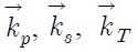
    are the wave-vectors of the pump, the Stokes and the THz wave, respectively. The phase-matching condition can be rewritten as

    image

    where θ is the angle between the pump wave and the Stokes wave.

    Usually, collinear phase-matching is the preferred configuration for a nonlinear frequency conversion process because it provides the longest interaction length. In recent years PPLN has been widely investigated for generating the THz radiation, which ensures two or even three mixing waves collinearly propagate, as is shown in Fig. 1 (b-e). In quasi-phase-matching configuration, the phase-matching condition

    image

    has to be fulfilled, where

    image

    is the grating vector of an alternating second-order nonlinearity induced by periodic poling of crystal. In the Fig. 1(b) the forwards parametric terahertz process is achieved by

    image

    being antiparallel to the pump

    image

    , the Stokes

    image

    and the THz-wave

    image

    wave-vectors. The backward parametric terahertz process is achieved by

    image

    travelling backward with respect to the pump

    image

    and the Stokes

    image

    , as is shown in Fig. 1(c). Most of the THz energy generated in the forwards and the backwards process is absorbed by the crystal due to the large absorption coefficients in the terahertz range. In Fig. 1(d), the grating vector

    image

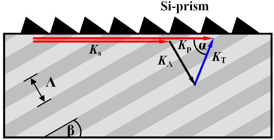
    is arranged perpendicular to the pump wave propagation direction, thereby allowing parallel propagation of the pump and the Stokes waves while still retaining the rapid exiting of the THz-wave through the side facet of the crystal. The generated THz-wave is extracted from the nonlinear crystal by an array of high resistivity Si-prisms avoiding total internal reflection. In Fig. 1(e), the pump and the Stokes wave are collinear, while the THz-wave propagates perpendicular to the side facet of the crystal. The THz-wave is coupled out without any coupler, so the loss is low and the beam quality is high.

    III. TUNING CHARACTERISTICS OF THE THZ-WAVE

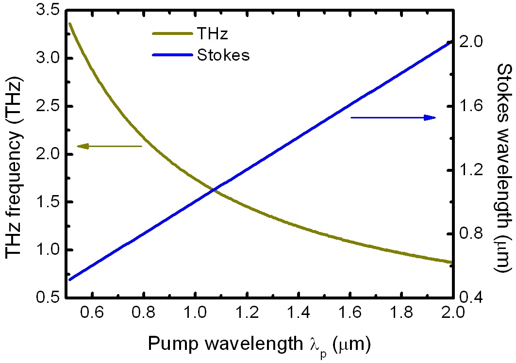
    Optical parametric oscillators are more versatile because of their tuning properties. In this section we analyze the tuning characteristics of the THz-wave based on the noncollinear phase-matching and the quasi-phase-matching configuration. According to the Eqs. (1) and (3), the tunable THz-wave frequency vT can be realized by varying the pump wavelength λp and the phase-matching angle θ. Such tuning is shown in Fig. 2. The THz-wave frequency vT is sensitive to the angle θ, so the rapid tuning can be reached by changing the angle θ. Different from the methods provided by other groups by rotating the gain medium or mirrors, [9,13] here we propose a method for realizing the tuning output of the THz-wave for the first time. A symmetric resonant cavity of the Stokes wave with a diamond configuration is proposed, as is shown in Fig. 3. The angle θ between the pump wave and the Stokes wave is tuned by moving the cavity mirror M3 backwards and forwards, as a result, the tuned THz-wave can be reached. The incidence angle of the pump wave θ0

    is set to ensure that the THz-wave with the frequency of 1.5 THz emits perpendicularly from the LiNbO3 crystal. The relationship between the initial position of the mirror M3 and the exit point of the THz-wave L is

    image

    Where R is half the distance between the mirror M1 and M2. The relationship between the movement distance ΔL of the mirror M3 and the phase-matching angle θ is

    image

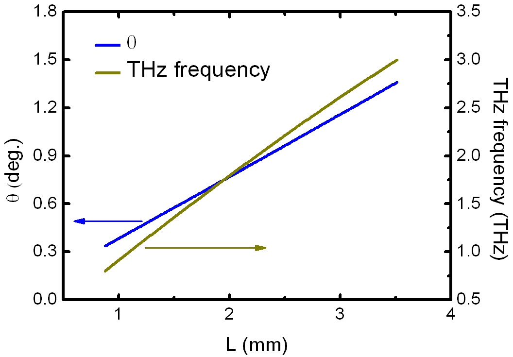
    According to the Eqs. (3) and (6) the tuning THz-wave can be realized by moving the mirror M3 backwards and forwards. Such tuning is shown in Fig. 4. The tuning range of 0.8-3 THz can be obtained by moving the M3 forwards from 0.87 to 3.51 mm. The method is simple and practical for the tuning output of the THz-wave.

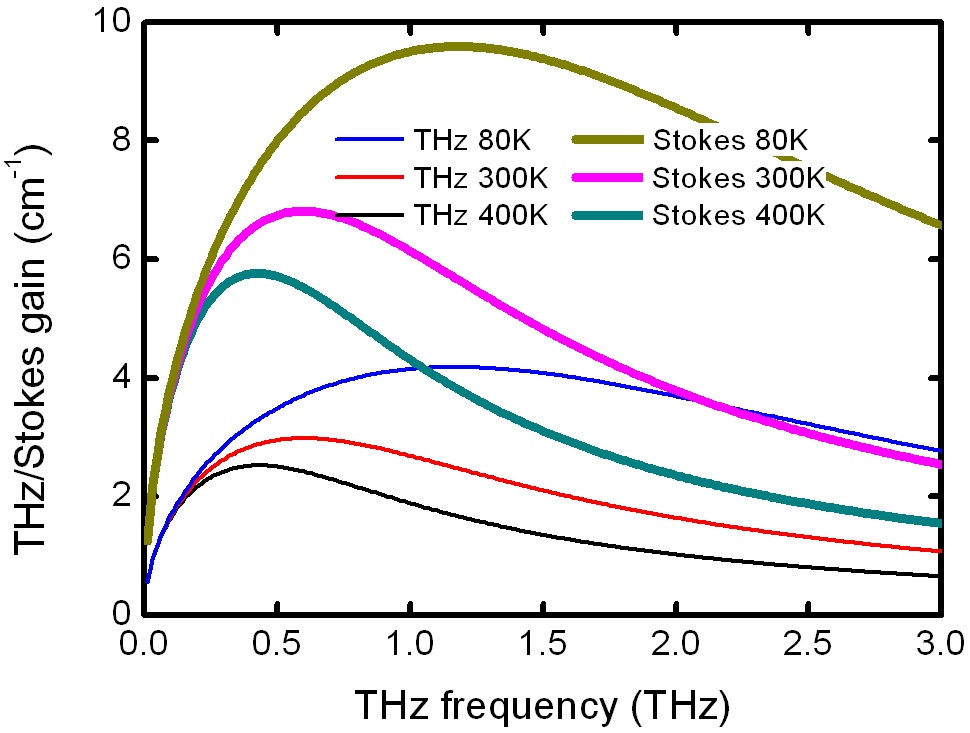
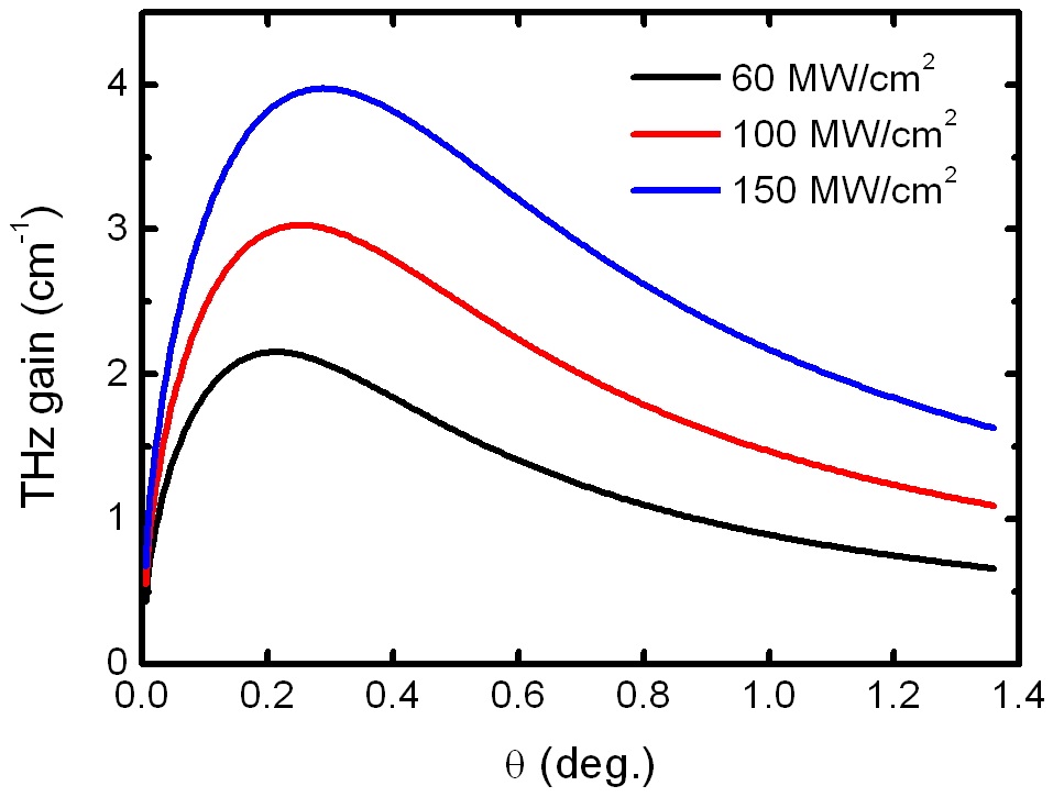
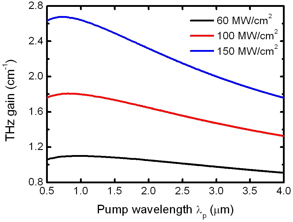
    In the process of the THz-wave generation, the THz-wave parametric gain is of vital importance. According to the Ref. (14), the analytical expressions of the exponential gain for the THz-wave can be written as
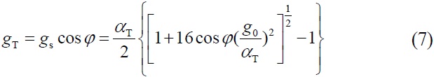
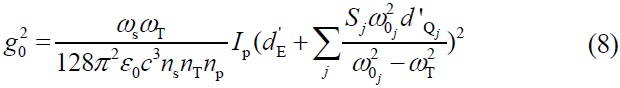
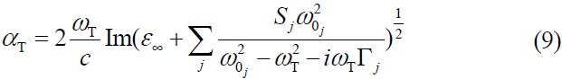
    image
    image
    image

    where φ is the phase-matching angle between the THz-wave and the pump wave, ω0j and Sj are the eigenfrequency and the oscillator strength of the lowest A1-symmetry phonon mode, respectively. Ip is the pump power density, gs is the gain coefficient of the Stokes wave. np, ns and nT are the refractive indices of the pump wave, the Stokes wave and the THz-wave, respectively. dE′ and dQ′ are related to the second-order and third-order nonlinear parametric processes, respectively. The values of parameters of Eqs. (7)-(9) are presented in Ref. (14). Fig. 5 shows the relationship between the THz-wave parametric gain coefficient gT and the angle θ as Ip equals to 60, 100 and 150 MW/cm2, respectively. From the figure we find the gT increases rapidly to the peak, and then decreases slowly to the lower values. The maximum values of the tuning curves move to the high frequency band as the Ip changes from 60 to 100 and 150 MW/cm2.

    The tuned THz-wave can be achieved also by varying the pump wavelength λp. Fig. 6 shows the relationship between the THz-wave frequency vT and the pump wavelength

    λp at room temperature. The vT decreases rapidly and slowly with the increase of the pump wavelength λp. The pump wavelength not only varies the THz-wave frequency, but also affects the parametric gain of the THz-wave. Fig. 7 shows the parametric gain coefficient gT with the changing of the pump wavelength λp. As the λp changes from 0.5 to 4 μm, the gT increases rapidly to the peak, and then decreases slowly to the lower values. From the figure we find that the maximum values of the tuning curves move to the lower wavelength band as the Ip changes from 60 to 100 and 150 MW/cm2.

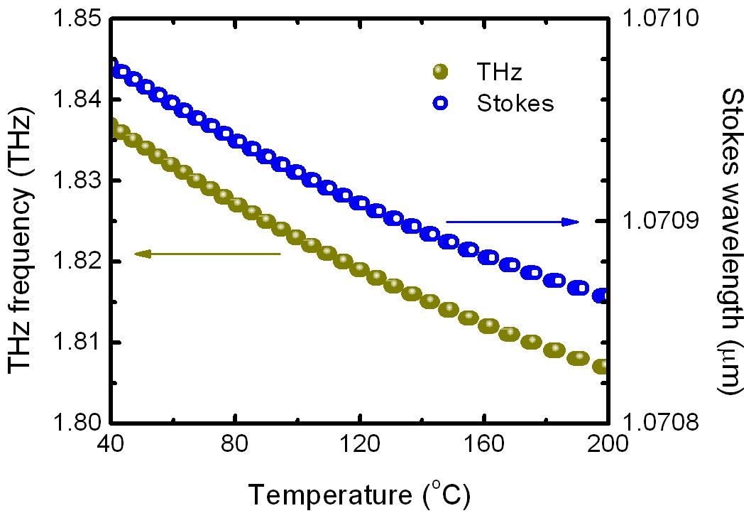
    The tuning THz-wave can be achieved by changing the working temperature of the LiNbO3 crystal. The relationship among the crystal temperature, the THz-wave frequency vT and the Stokes wavelength λp is shown in Fig. 8. Temperature dependence of the refractive index of the LiNbO3 crystal in the terahertz range is reported in Ref. (12). As the temperature varies from 40℃ to 200℃, the THz-wave in the range of 1.81-1.84 THz can be obtained. Compared with the tuning characteristics by varying the

    phase-matching and the pump wavelength, the THz-wave frequency is insensitive to the working temperature. The crystal temperature not only affects the phase-matching condition, but also has a significant impact on the parametric gain coefficient gT and gs. The characteristics of gT and gs at different temperatures are shown in Fig. 9. From the figure we find that the gT and gs increase along with the decrease of the temperature. The damping coefficient of the lowest A1-symmetry phonon mode in the LiNbO3 crystal reduces with the decrease of the temperature[15], resulting in the enlargement of the parametric gain. As discussed above, the enhanced output of the THz-wave can be realized by reducing the working temperature.

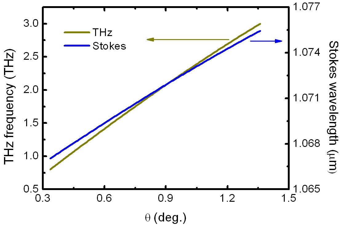
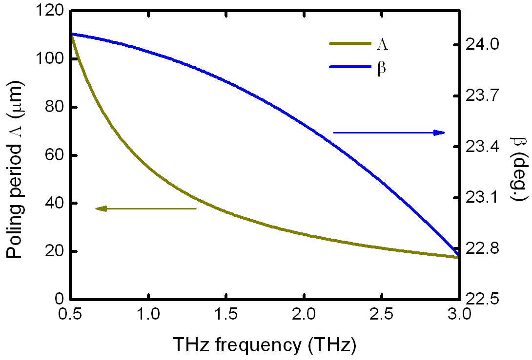
    The tuning output of the THz-wave can be realized in quasi-phase-matching configuration by varying the poling period of the PPLN crystal and the phase-matching angle. In this section we analyze the tuning characteristics based on the model shown in Fig. 1(e), since the THz-wave is coupled out perpendicularly to the side surface of the PPLN crystal without using any output coupler. According to the Fig. 1(e), the poling period Λ and the phase-matching angle
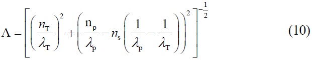
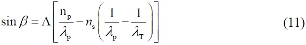
 β between the THz-wave propagation direction and the grating vector are

    image
    image

    Where λT is the wavelength of the THz-wave. The tuning THz-wave versus the phase-matching angle β and poling period Λ at room temperature is shown in Fig. 10. With the increase of the THz-wave frequency vT, the poling period Λ decreases rapidly and then slowly, while the

    angle β decreases slowly and then rapidly. At the point of 1.5 THz where the output of the THz-wave is of the most intensity [16], the poling period Λ equals to 36.5 μm and the angle β equals to 23.8°.

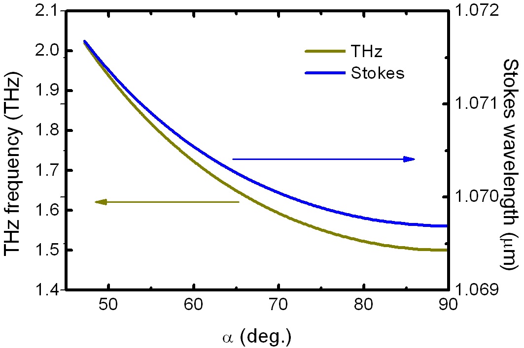
    As the THz-wave propagation direction is not perpendicular to the side surface of the PPLN crystal, the THz-wave can be coupled out by employing an array of Si-prisms to avoid total internal reflection [16,17], as is shown in Fig. 11. The angle α is between the THz-wave wave-vector and the pump wave wave-vector. The relationship between the angle α and the THz-wave wavelength λT is

    image

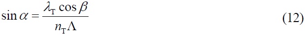
    According to the Eqs. (1) and (12), the tuning THz-wave with different propagation directions can be realized in a PPLN crystal with a fixed poling period Λ and a fixed angle β by employing a tuning Stokes seed beam. Such tuning is shown in Fig. 12, assuming the poling period Λ of 36.5 μm and the angle β of 23.8° where the THz-wave output is the most intense. Since the refractive indexes of the THz-wave in LiNbO3 crystal and high-resistivity Si are

    approximately 5.1 and 3.4 respectively, the minimum value of the angle α is 47.2° to avoid total internal reflection of the THz-wave. From the figure we find that by injecting the tuning Stokes seed beam in the range of 1069.7-1071.7 nm we can obtain the tuning THz-wave from 1.5 to 2.02 THz. The analysis here provides a choice for the tuning THz-wave by employing a PPLN crystal with a fixed poling period Λ and a fixed angle β.

    IV. CONCLUSION

    The THz-wave tuning characteristics of the noncollinear phase-matching TPO and the quasi-phase-matching TPO are investigated. In the condition of the noncollinear phase-matching configuration, the THz-wave frequency is sensitive to the variation of the phase-matching angle θ and the pump wavelength λp, while insensitive to the variation of the crystal temperature. The phase-matching angle θ, the pump wavelength λp and the crystal temperature affect the parametric gain coefficients of the THz-wave. The tuning THz-wave can be realized in quasi-phase-matching configuration by varying the poling period of the PPLN crystal and the phase-matching angle. Employing the PPLN crystal with the poling period Λ of 36.5 μm and the angle β of 23.8°, we can obtain the tuning THz-wave from 1.5 to 2.02 THz by injecting the Stokes seed beam with the wavelength λs in the range of 1069.7-1071.7 nm.

참고문헌
  • 1. Kim Y., Jin K. H., Ye J. C., Ahn J., Yee D. (2011) “Wavelet power spectrum estimation for high-resolution terahertz time-domain spectroscopy” [J. Opt. Soc. Korea] Vol.15 P.103-108 google cross ref
  • 2. Kang C., Kee C., Sohn I., Lee J. (2008) “Spectral properties of THz-periodic metallic structures” [J. Opt. Soc. Korea] Vol.12 P.196-199 google cross ref
  • 3. Wang Y. Y., Minamide H., Tang M., Notake T., Ito H. (2010) “Study of water concentration measurement in thin tissues with terahertz-wave parametric source” [Opt. Express] Vol.18 P.15504-15512 google cross ref
  • 4. Jung E., Lim M., Moon K., Do Y., Lee S., Han H., Choi H., Cho K., Kim K. (2011) “Terahertz pulse imaging of micro-metastatic lymph nodes in early-stage cervical cancer patients” [J. Opt. Soc. Korea] Vol.15 P.155-160 google cross ref
  • 5. Kleine-Ostmann T., Nagatsuma T. (2011) “A review on terahertz communications research” [J. Infrared Milli. Terahz. Waves] Vol.32 P.143-171 google cross ref
  • 6. Liu H. B., Zhong H., Karpowicz N., Chen Y., Zhang X. C. (2007) “Terahertz spectroscopy and imaging for defense and security applications” [Proc. IEEE] Vol.95 P.1514-1527 google cross ref
  • 7. Rutz F., Koch M., Khare S., Moneke M., Richter H., Ewert U. (2006) “Terahertz quality control of polymeric products” [Int. J. Infrared Millimeter Waves] Vol.27 P.547-556 google
  • 8. Kang C., Lee Y. L., Jung C., Yoo H. K., Kee C. (2010) “Effects of uncertain phase-matching wave vectors of rotating fan-out type poled LiNbO3 on THz generation” [Opt. Express] Vol.18 P.21484-21489 google cross ref
  • 9. Kawase K., Shikata J., Ito H. (2001) “Terahertz wave parametric source” [J. Phys. D: Appl. Phys.] Vol.34 P.R1-R14 google cross ref
  • 10. Kiessling J., Fuchs F., Buse K., Breunig I. (2011) “Pumpenhanced optical parametric oscillator generating continuous wave tunable terahertz radiation” [Opt. Lett.] Vol.36 P.4374-4376 google cross ref
  • 11. Molter D., Theuer M., Beigang R. (2009) “Nanosecond terahertz optical parametric oscillator with a novel quasi-phase-matching scheme in lithium niobate” [Opt. Express] Vol.17 P.6623-6628 google cross ref
  • 12. Sowade R., Tulea C., Buse K. (2010) “Nonlinear coefficient and temperature dependence of the refractive index of lithium niobate crystals in the terahertz regime” [Appl. Phys. B] Vol.99 P.63-66 google cross ref
  • 13. Minamide H., Ikari T., Ito H. (2009) “Frequency-agile terahertzwave parametric oscillator in a ring-cavity configuration” [Rev. Sci. Instrum.] Vol.80 P.123104 google cross ref
  • 14. Sussman S. S. (1970) “Tunable light scattering from transverse optical modes in lithium niobate” P.22-34 google
  • 15. Johnston W. D. Jr., Kaminow I. P. (1968) “Temperature dependence of Raman and Rayleigh scattering in LiNbO3 and LiTaO3” [Phys. Rev.] Vol.168 P.1045-1054 google cross ref
  • 16. Ikari T., Zhang X. B., Minamide H., Ito H. (2006) “THz-wave parametric oscillator with a surface-emitted configuration” [Opt. Express] Vol.14 P.1604-1610 google cross ref
  • 17. Kawase K., Shikata J., Minamide H., Imai K., Ito H. (2001) “Arrayed silicon prism coupler for a terahertz-wave parametric oscillator” [Appl. Opt.] Vol.40 P.1423-1426 google cross ref
OAK XML 통계
이미지 / 테이블
  • [ FIG. 1. ]  Phase-matching schemes. (a) Noncollinear phasematching. (b) Quasi-phase-matching, grating vector parallel to the pump wave propagation and the THz-wave propagation direction along with pump wave propagation. (c) Quasi-phasematching, grating vector parallel to the pump wave propagation and the THz-wave travelling backwards with respect to the pump wave propagation. (d) Quasi-phase-matching scheme with grating vector perpendicular to the pump wave propagation. (e) Slant-stripe periodic poling for quasi-phasematching, the THz-wave propagation direction perpendicular to the pump wave propagation.
    Phase-matching schemes. (a) Noncollinear phasematching. (b) Quasi-phase-matching, grating vector parallel to the pump wave propagation and the THz-wave propagation direction along with pump wave propagation. (c) Quasi-phasematching, grating vector parallel to the pump wave propagation and the THz-wave travelling backwards with respect to the pump wave propagation. (d) Quasi-phase-matching scheme with grating vector perpendicular to the pump wave propagation. (e) Slant-stripe periodic poling for quasi-phasematching, the THz-wave propagation direction perpendicular to the pump wave propagation.
  • [ FIG. 2. ]  THz-wave frequency vT versus the phase-matching angle θ and the Stokes wavelength λs at room temperature, λp=1064 nm.
    THz-wave frequency vT versus the phase-matching angle θ and the Stokes wavelength λs at room temperature, λp=1064 nm.
  • [ FIG. 3. ]  A symmetric resonant cavity of the Stokes wave with a diamond configuration. The cavity mirror M3 can move backwards and forwards to acquire the tuning angle θ.
    A symmetric resonant cavity of the Stokes wave with a diamond configuration. The cavity mirror M3 can move backwards and forwards to acquire the tuning angle θ.
  • [ FIG. 4. ]  The movement distance ΔL of the mirror M3 versus the angle θ and the THz-wave frequency vT, R=60 mm, θ0= 63.53°.
    The movement distance ΔL of the mirror M3 versus the angle θ and the THz-wave frequency vT, R=60 mm, θ0= 63.53°.
  • [ FIG. 5. ]  The parametric gain coefficient gT versus the angle θ at room temperature, λp=1064 nm, Ip=60, 100 and 150 MW/cm2, respectively.
    The parametric gain coefficient gT versus the angle θ at room temperature, λp=1064 nm, Ip=60, 100 and 150 MW/cm2, respectively.
  • [ FIG. 6. ]  The THz-wave frequency vT versus the pump wavelength λp and the Stokes wavelength λs at room temperature, θ=0.7°.
    The THz-wave frequency vT versus the pump wavelength λp and the Stokes wavelength λs at room temperature, θ=0.7°.
  • [ FIG. 7. ]  The parametric gain coefficient gT versus the pump wavelength λp at room temperature, θ=0.7o, Ip=60, 100 and 150 MW/cm2, respectively.
    The parametric gain coefficient gT versus the pump wavelength λp at room temperature, θ=0.7o, Ip=60, 100 and 150 MW/cm2, respectively.
  • [ FIG. 8. ]  The temperature tuning characteristics of the THz-wave, λp=1064 nm, θ=0.7°.
    The temperature tuning characteristics of the THz-wave, λp=1064 nm, θ=0.7°.
  • [ FIG. 9. ]  Gain coefficients of the THz-wave and the Stokes wave, λp=1064 nm, Ip=100 MW/cm2.
    Gain coefficients of the THz-wave and the Stokes wave, λp=1064 nm, Ip=100 MW/cm2.
  • [ FIG. 10. ]  The THz-wave frequency vT versus the phase-matching angle β and poling period Λ at room temperature, λp=1064 nm.
    The THz-wave frequency vT versus the phase-matching angle β and poling period Λ at room temperature, λp=1064 nm.
  • [ FIG. 11. ]  Schematic diagram of the quasi-phase-matching in PPLN crystal as the THz-wave wave-vector is not perpendicular to the the side surface of the PPLN crystal.
    Schematic diagram of the quasi-phase-matching in PPLN crystal as the THz-wave wave-vector is not perpendicular to the the side surface of the PPLN crystal.
  • [ FIG. 12. ]  The THz-wave frequency vT versus the angle α and the Stokes wavelength λs at room temperature, Λ=36.5 μm, β =23.8o, λp=1064 nm.
    The THz-wave frequency vT versus the angle α and the Stokes wavelength λs at room temperature, Λ=36.5 μm, β =23.8o, λp=1064 nm.
(우)06579 서울시 서초구 반포대로 201(반포동)
Tel. 02-537-6389 | Fax. 02-590-0571 | 문의 : oak2014@korea.kr
Copyright(c) National Library of Korea. All rights reserved.