Optical Coherence Tomography (OCT) is an imaging technology which is based on a light source of low coherence length. High resolution images (1 ~ 15 μm) of cross sections from living samples can be acquired by using OCT technology, noninvasively and in real-time [1-3]. OCT has been applied to early diagnosis instruments for cancer and various diseases. A lot of research is being done into applying OCT to ophthalmology, dermatology, internal medicine, dentistry and gynecology [4-9]. Due to technology development using GPU, much research into the application of OCT to auxiliary instruments for operations is now being carried out. The GPU has more ALU (Arithmetic and Logic Unit) than a CPU (Central Processing Unit), so its processing speed is high whereas its cost is lower. Because of those merits and the need for more computation power, there are many studies about OCT using the GPU in the imaging field [10,11].
In this study, we first compared the processing speed using the GPU and the CPU in each step for applying to real-time auxiliary instruments for operations in ophthalmology. Secondly, to measure the processing performance of a GPU, the processing speeds for different image sizes were compared. Thirdly, we measured and compared the data acquisition time for different image sizes. Last, real-time display speeds were compared using a 1024 × 512 image with each processing unit. Because there was much movement in the ophthalmologic operation, we took 2D images of the retina for confirmation of availability to the operation auxiliary instrument. We performed an experiment that confirms the effect of motion artifacts by reconstructing a 3D optic disk from the 2D image. As a result, each cross section and blood vessel, and the optic nerves are clearly observed.
II. EXPERIMENTAL SETUP AND RESULT
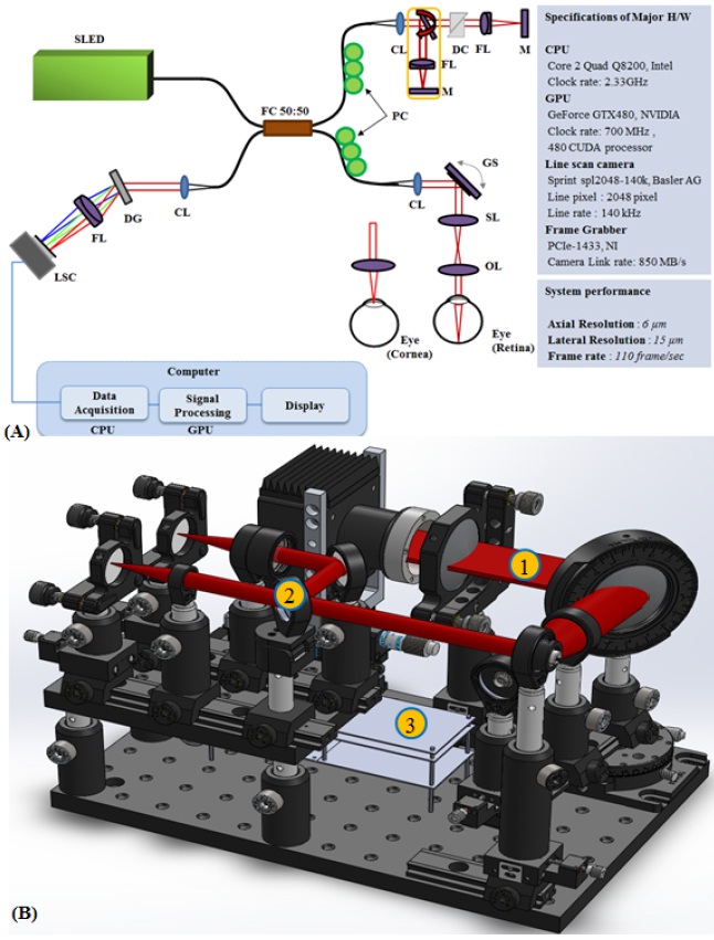
A schematic diagram of the GPU accelerated mode realtime display SD-OCT system is shown in Fig. 1. (A) A 12-bit CMOS line scanning camera (Sprint spL2048-140 k, Basler AG) with 70,000 line/sec effective line rate at 2,048 pixel mode was used as the detector of the GPU accelerated mode real-time display SD-OCT system. The transmission type diffraction grating (Spatial Frequency 1,800 lpmm, Nominal AOI/AOD 46.05 Degrees, Wasatch Photonics) was adapted to enhance light efficiency in the detection path. Combined with a superluminescence diode (SLED) (λ0 = 850 nm, Δλ = 55 nm, Exalos AG) as a light source, a fiberbased interferometer was implemented. The light source was split into sample and reference arms terminated by a stationary mirror. The reference arm for retinal imaging also contained a dispersion compensation unit (prism pair)
to account for the dispersion within the optics of the human eye and the sample arm. A probe at the end of the sample arm delivered light to a sample and collected backscattered light from different depths in the sample. B-mode scanning was performed using a galvanometer scanner (GVS002, Thorlabs) at the back focal plane of the objective lens at the sample arm. The developed system has axial and lateral resolutions of 6 μm and 15 μm, respectively. The detected OCT signals were transferred to a host memory in the computer mounted with four CPUs (Core 2 Quad Q8200, 2.33 GHz Clock rate, Intel) through a frame grabber (PCIe-1433, 850 MB/s Bandwidth, National Instruments). The galvanometer scanner was driven by the computer with a data acquisition board (PCIe-6321, National Instruments). The computer also contained a graphics card (GeForce GTX 480, 700 MHz Clock rate, 480 CUDA processor, NVIDIA). Fig. 1(b) is a schematic of the developed system rendered using a 3D CAD (Computer Aided Design) tool (Solid works 2012). The ratio of the schematic is 1:1 to the real size of the optics, so we can shorten the fabrication time of the OCT system by designing it, first with the CAD program. ① is the spectrometer part of the system, and it shows the beam path. To make the beam size large for better resolution, we used a fiber adaptor lens (LA1608, Thorlabs) for a collimated beam. So, we could acquire the highest resolution using a beam size of 15 mm. We used a flip mirror for comfortable path length adjustment when we image the retina and cornea, which is shown in ②. By using the flip mirror, we could shorten the experimental time. ③ is the light source which is mounted on breadboard for miniaturizing the system.
2.2. GPU Accelerated Mode SD-OCT System Software System and Performance
In order to apply GPU technology to OCT signal processing, an optimum combination of CPU and GPU is designed [12]. Two separate buffers are allocated in the host memory of the CPU and they are assigned as one CPU thread. These buffers are mainly dedicated for temporal data storage right after data acquisition. Due to the limited data transfer channel between the CPU and GPU careful data handling was necessary to minimize any bottleneck events during the data transfer. We report a significant decrease in the processing time when we use host memory to allocate the acquired data. The conventional method utilizing the memory in the frame grabber requires 16 ms of processing for 2,048 × 512 pixels of data compared to 8.3 ms using the proposed two separate buffer method. As a device memory in the GPU, the signal processing job is divided into 480 CUDA processors.
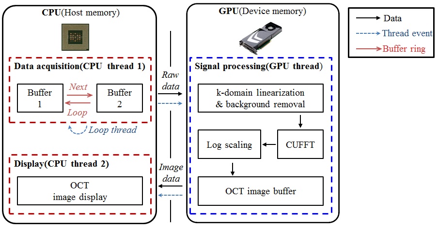
Figure 2 displays the data flow chart for the GPU accelerated mode SD-OCT system including the flow of data path, thread events, and the buffer ring. First the data acquisition thread stores incoming two-dimensional signals into the first buffer allocated in the host memory and calls a signal processing thread. Later, the self-iterated acquisition thread continuously transfers the incoming signals to the second buffer without any temporal delay between the
acquisition events. The signal processing thread copies the frame data stored in the buffers of the host memory through the PCI express ×16 2.0 interface into the device memory. Later, the processing divides 480 CUDA subprocessors to further process the signal for OCT. K-domain linearization is completed using the full-range k-domain linearization [13,14]. By removing the background noise, the speckle of the source can be minimized and the images with high resolution can be obtained as well [2,15]. The background noise removal method removes the noise by comparing the difference between acquired B-scan data of the existing OCT system signal with B-scan data of the changed OCT system and by subtracting the difference. The reconstructed OCT images are transferred back to the host memory to be real-time displayed.
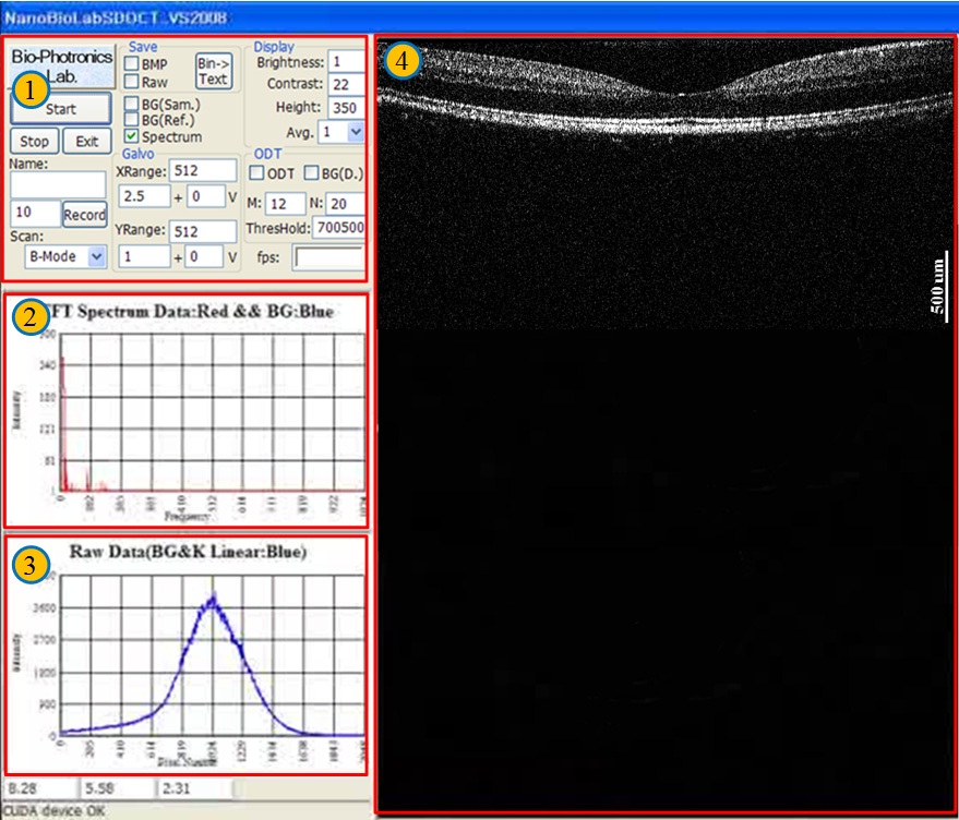
Figure 3 is the UI (User Interface) of the developed software. We made a driving program based on the MFC (Microsoft Foundation Class) of Visual C++ 2008. The CUDA toolkit version 3.2 was used. ① is the system configuration part which can control the program driving status (on or off), saving mode of the data, brightness, contrast, scan mode, scan range, image size and graph of spectrum output. ② is the FFT spectrum output for analyzing the A-scan profile, and ③ is the raw spectrum for confirming the system status. Last, ④ is the real-time image part of OCT to show the output image to users.
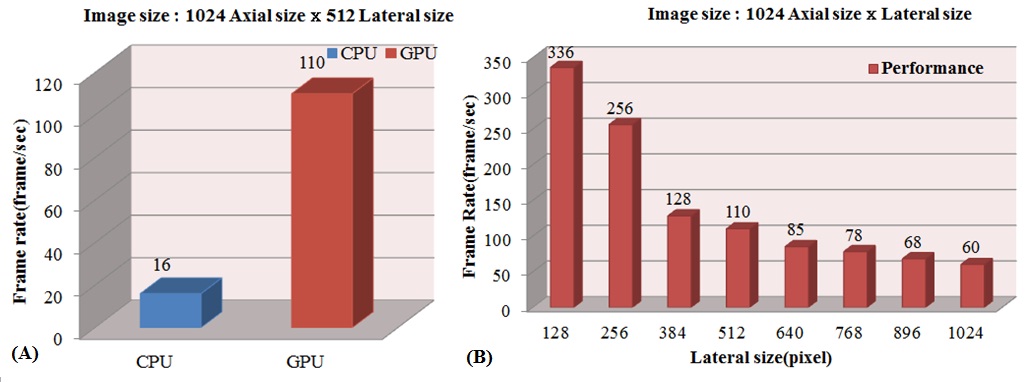
Figure 4 is measured performance characteristics according to the image size. Fig. 4(a) is the performance comparison of the system when it uses the CPU and GPU for signal processing. When we use the GPU accelerated mode, the image output speed was 110 frame/sec. On the other hand, in the case of using the multi-core system, the image output speed was 16 frame/sec. We confirmed that the image output speed was improved by 6.9 times. Video output speed is lower than the signal processing speed because the speed of data acquisition is fixed at 8.3 ms. It is affected by the performance of the line scan camera, so we can improve this problem by using a faster camera. Fig. 4(b) is the speed comparison data in GPU processing according to the image size. When the image size is 1024 × 128, the output speed reaches up to 336 frame/sec. As the image size decreased, the output speed may be improved. The image size and the imaging speed are mainly dependent on the acquisition rate of the line scan camera. Therefore, the video output speed can be improved if a qualitative line camera is used.
Table 1 is the comparison data of the processing speed when only using a multi-core system for confirming the performance of the GPU accelerated mode real-time display SD-OCT system. We realized and compared the processing in the CPU using the same iteration structure, and used an Intel Core2Quad Q8200 CPU, version 3.3 of the FFTW library FFT arithmetic operation. The FFT arithmetic operation in GPU processing was version 3.2 of the CUFFT library from NVidia. We measured the averaged data of 500 images, and the image size was 1024 × 512 pixels. In the case of the CPU processing, there is no procedure of transmitting the data from the processing unit to the
[TABLE 1.] Comparison in processing time between processors that use CPU and GPU
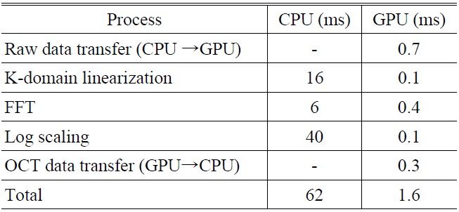
Comparison in processing time between processors that use CPU and GPU
memory, so data transmitting is not necessary. Nevertheless, when we used the GPU accelerated mode, we confirmed a performance improvement of 160 times in the k-domain linearization process, 15 times in the FFT process and 400 times in the log scaling process. Total processing time was 1.6 ms with GPU accelerated mode processing, and 62 ms with sole CPU processing. Performance was improved by 38 times as shown in Table 1.
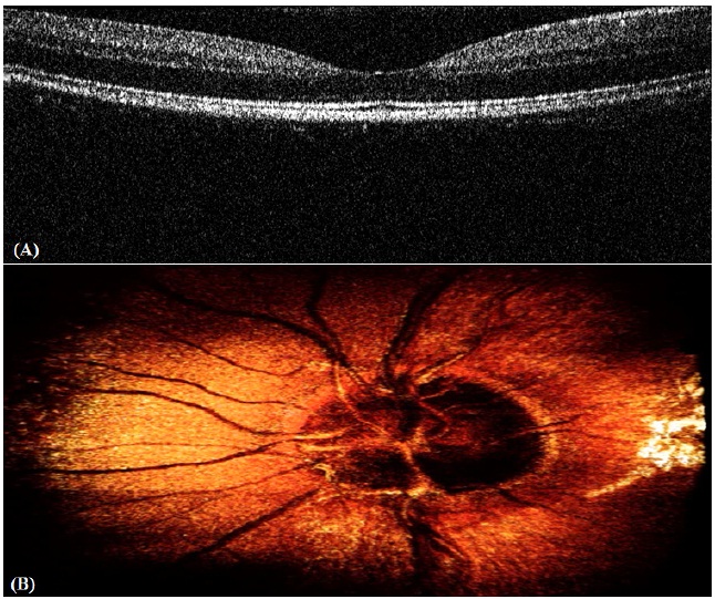
Figure 5 is the image data used by the accelerated realtime display SD-OCT system. Fig. 5(a) is the real time image of an in vivo human retina with a resolution of 1024 × 512. The image output speed was 110 frame/sec, and the movement of the eye can be confirmed from the movie. Fig. 5(b) is a reconstructed 3D image of the in vivo human optic disk from the 2D image acquired by the C-scan. Blood vessels and optic nerves were clearly observed. We could confirm that the imaging speed is fast enough to ignore motion artifacts.
In this paper, first we compared the signal processing speed of a conventional CPU and a GPU accelerated mode for applying to real-time display auxiliary instruments for an ophthalmologic operation. When we used the GPU accelerated mode processing, the speed was improved by 6.9 times compared to the CPU processing. Secondly, we compared the image output speed according to image size for measuring the arithmetic performance of the GPU. The speed was about 110 frames per second when the image size was 1024 × 512 pixels. Thirdly, we measured the data acquisition speed according to the image size. The DAQ speed was improved by 38 times when we used the GPU accelerated processing rather than the CPU processing. Finally, we compared and measured the real-time display speed of 1024 × 512 which value is optimized for OCT image. As the result, the real-time imaging was reliably performed avoiding the motion artifacts caused by eye movement, and the blood vessels and the optic nerve were clearly observed as a connected structure. Real-time display based on these results in this paper, the developed OCT system can be applied to auxiliary instruments for ophthalmologic operations. The ability to check the status of the patient and the surgery particularly during a lens implantation, glaucoma surgery and cornea incision convinces the reliability of the OCT system.