검색 전체 메뉴
PDF
맨 위로
OA 학술지
Optical VSB Filtering of 12.5-GHz Spaced 64 × 12.4 Gb/s WDM Channels Using a Pair of Fabry-Perot Filters
  • 비영리 CC BY-NC
  • 비영리 CC BY-NC
ABSTRACT
Optical VSB Filtering of 12.5-GHz Spaced 64 × 12.4 Gb/s WDM Channels Using a Pair of Fabry-Perot Filters
KEYWORD
Optical communication , Optical modulation , Wavelength division multiplexing , Fabry-Perot filter , Vestigial sideband filtering
  • I. INTRODUCTION

    Optical vestigial sideband (VSB) filtering is a useful method for optical transmission systems to increase spectral efficiencies and transmission distances [1-9]. It carves out one of the sidebands from a modulated optical channel using narrow optical filters which will be called VSB filters here. The other sideband still retains the entire modulation information. Optical VSB filtering, henceforth VSB filtering, is simple and additional costs are low.

    Recently, coherent optical communication systems have been investigated extensively and will likely be used for 100-Gb/s and higher wide-area networks [10,11]. In this case, the two sidebands of a single channel usually have different information. However, the coherent optical communication systems need many subsidiary devices such as lasers, radio-frequency (RF) driver amplifiers, photodiodes, and heavy digital signal processing circuits. Thus the VSB filtering will be still popular, especially in metro and access networks where many wavelength-division-multiplexing (WDM) channels would be used with relatively low bit rates.

    The VSB filters should have steep skirts in transmittance curves to remove one of the sidebands efficiently. This is important especially for relatively low bit rate channels in metro and access networks. In addition, it will be advantageous to use a single VSB filter for multiple WDM channels in a parallel way. This property is important to reduce the cost when the channel number is large. Typical VSB filters reported to date are Mach-Zehnder filters [1,2], fiber-Bragg gratings [3,4], optical band-pass filters [5-7], WDM demultiplexers [8], and optical interleavers [9]. The bit rate of [1] is 6 Gb/s. The bit rates of [2], [3], [8], and [9] are ~10 Gb/s. In other cases, channel bit rates are much higher than 10 Gb/s. Usually, a single VSB filter is needed per channel. In [8] and [9], 8 channels are VSB filtered simultaneously using a single VSB filter.

    In this paper, we suggest using a pair of Fabry-Perot (FP) filters for the VSB filtering. Each FP filter covers even

    or odd channels separately. With an offset between input and output coupling fibers, the FP filters may have very steep skirts in transmittance curves [12]. Moreover, the FP filters naturally have a very accurate periodicity in spectral domain and are appropriate for the simultaneous VSB filtering of many WDM channels. In our experiment, we perform a VSB filtering of 12.5-GHz spaced 64 × 12.4 Gb/s WDM channels. After the VSB filtering, we transmit the WDM channels over a conventional single mode fiber (SMF) of 150 km without any dispersion compensations. To our knowledge, this is the first VSB filtering experiment using FP filters.

    II. EXPERIMENT

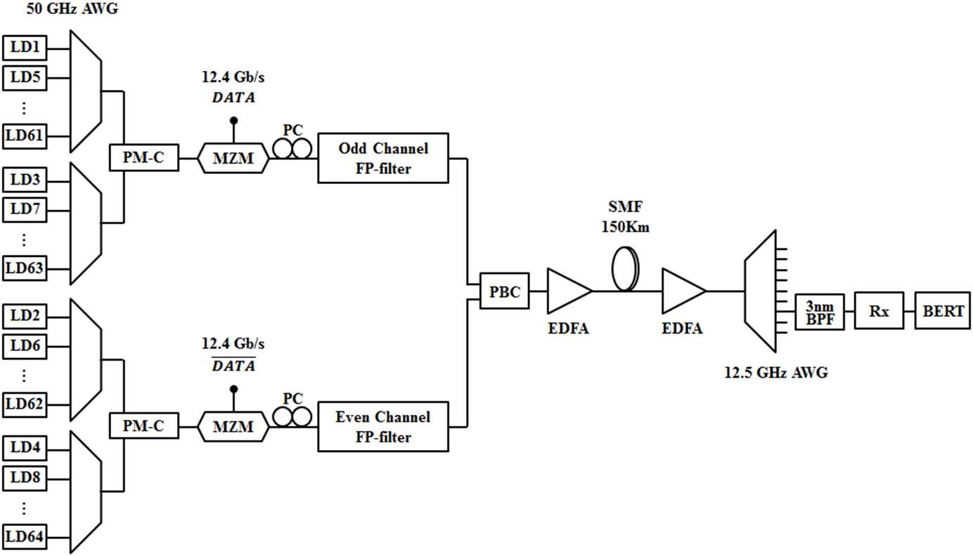
    Our experimental setup is illustrated in Fig 1. The channel wavelengths ranged from 1554.2 nm to 1560.5 nm with the channel spacing of 12.5 GHz. Four 50-GHz arrayed waveguide gratings (AWGs) were used to multiplex these channelsnel wavelengths were monitored using a wavelength meter. The output power of each laser diode was 0 dBm. Even and odd channels were externally modulated using data and delayed data-bar signals, respectively. The data signal was a 231-1 pseudorandom bit sequence. The modulation format was non-return-to-zero type and the bit rate was 12.4-Gb/s assuming a block-turbo-code (BTC) based forward-error correction (FEC) [13]. Its FEC threshold is at 1.98 × 10-2 bit error rate (BER) corresponding to a quality factor Q = 6.26 dB.

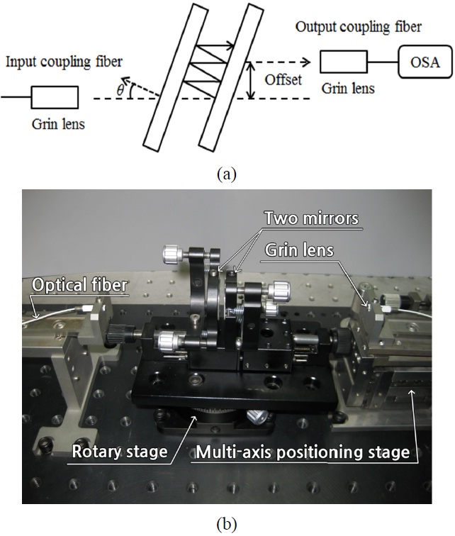
    The VSB filtering was done separately for even and odd channels using a pair of FP filters. Fig. 2(a) shows the FP filter structure used in our experiment. The FP filter consisted of input/output coupling fibers and two parallel

    glass plate mirrors with a reflectivity of 30 %. The freespectral range (FSR) of the FP filter was 25 GHz obtained by adjusting the distance between two dielectric mirrors. The beam incidence angle to these mirrors, denoted as θ, was 0.5° for the even channel FP filter. It was 0.75° for the odd channel FP filter. We introduced an offset of 200 μm between the input and the output coupling fibers to increase the slopes of skirts in FP filters’ transmittance curves [12]. The filter insertion losses were 8.1 dB and 8.8 dB for the even and the odd channel FP filters, respectively. Also, we show a photograph of our Fabry-Perot filter in Fig. 2(b). The position of the right coupling fiber was adjusted using a multi-axis positioning stage while the left coupling fiber was fixed. The two mirror mounts were fixed on a rotary stage.

    After the VSB filtering, the even and the odd channels were polarization multiplexed using a polarization beam combiner (PBC). The PBC output was amplified using an erbium-doped fiber amplifier (EDFA) and transmitted over an SMF of 150 km. The total launched power was 15 dBm. After the transmission, the received channels were demultiplexed using a 12.5-GHz AWG.

    After the 12.5-GHz AWG, we used a tunable 3-nm optical filter to obtain a single channel. The 12.5-GHz AWG had a loss of about 6.1 dB. Unfortunately, the 12.5-GHz AWG had only 24 outputs. Thus its temperature was adjusted to measure the whole 64 channels. The optical power was ?12 dBm at the receiver input. A pin photodiode was used at the receiver. We also performed the same experiment changing the bit rate to 10.7 Gb/s assuming a Reed-Solomon (RS) based FEC that has the FEC threshold at BER = 1 × 10⁻⁴ or Q = 11.4 dB [14].

    III. RESULTS AND DISCUSSION

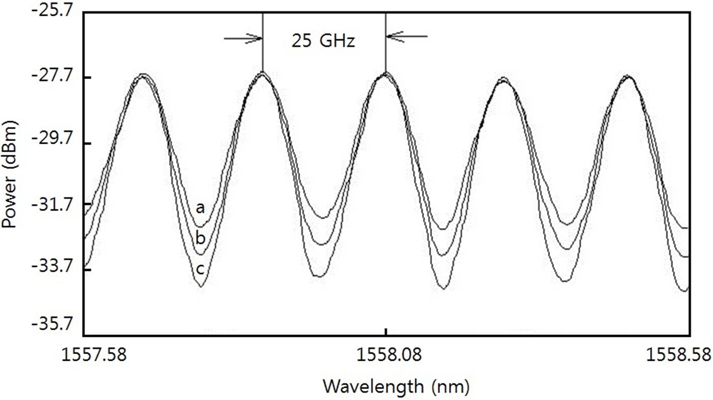
    In Fig. 3, we show the transmittance curves of the odd channel FP filter obtained by applying the amplified spontaneous emission from an EDFA. Three offset values, 0, 100, and 200 μm, are compared. The optical resolution is 0.05 nm. The transmission peak levels are adjusted to be the same. As the offset increases, the skirts become steeper. The insertion losses are 7.5, 7.7, and 8.8 dB for the offset values 0, 100, and 200 μm, respectively. We have fixed the offset to 200 μm in our experiment throughout.

    As θ increases, the transmittance peak wavelengths of the FP filters move towards longer wavelengths where we have higher insertion losses and wider transmission bandwidths [12]. In contrast, when θ is too small, the slopes of the transmittance skirts become insensitive to the offset. We have used these properties to implement the even and the odd channel FP filters. For the even channel FP filter, the appropriate θ values for the VSB filtering are 0.5°, 1.0°, 1.5°, etc. We have chosen θ = 0.5° at which the insertion loss and the 3-dB bandwidth are 8.1 dB and 14.8 GHz, respectively. For example, at θ = 1.0°, the insertion loss and the 3-dB bandwidth are 11.9 dB and 16 GHz, respectively. Similarly, for the odd channel FP filter, we have chosen θ = 0.75° where the insertion loss and the 3-dB bandwidth are 8.8 dB and 15.1 GHz, respectively. We have not chosen θ = 0.25° since the skirts are not steep. The FP filter transmission peaks are 0.05 nm shifted to longer wavelengths from the channel centers.

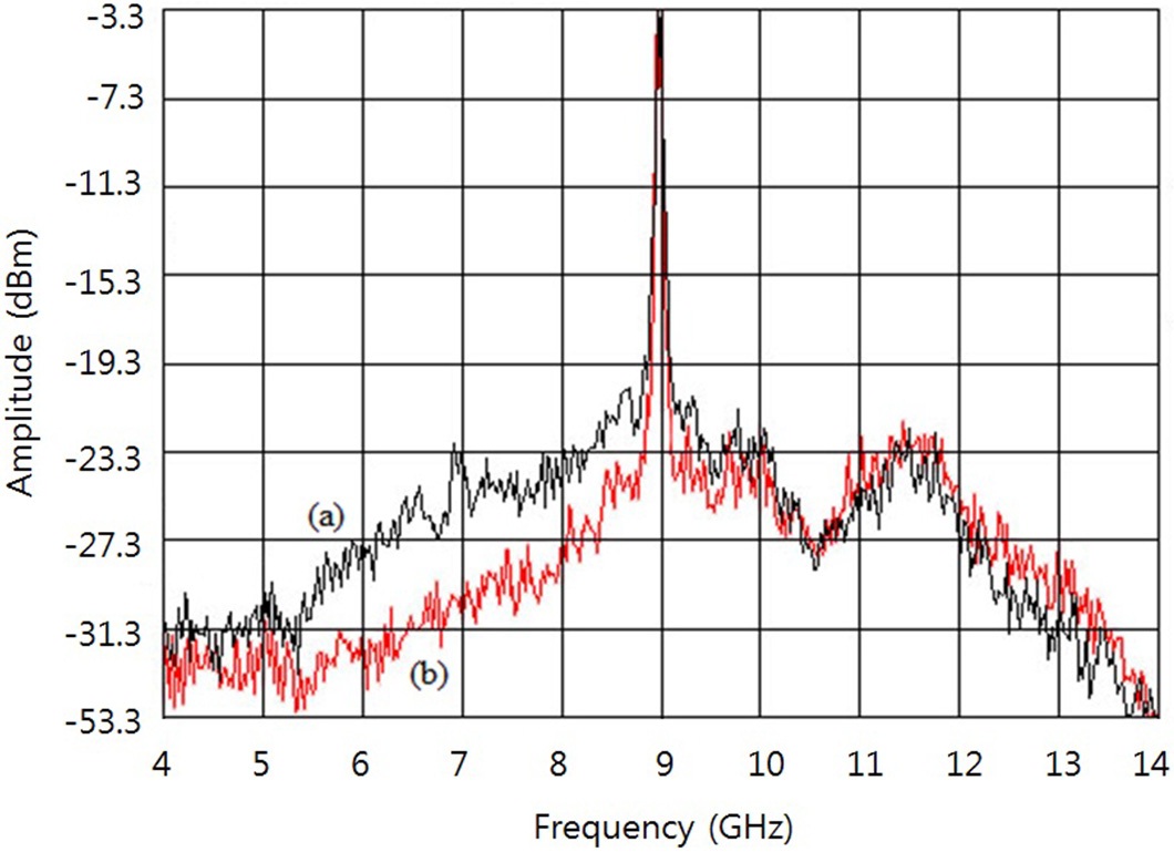
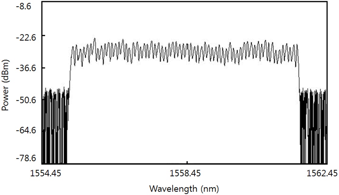
    Figure 4 shows the RF spectra of the 41st channel before and after the odd channel FP filter measured by a heterodyne detection with a tunable laser [15]. The tunable laser line is placed near the end of the sideband suppressed by the VSB filtering. Note that the RF spectra in Fig. 4 are for electrical fields not intensities. The suppression of the sideband intensity is twice that of the fields, around 10 dB. The heterodyne detection gives very precise shapes of fields before and after the VSB filtering. Fig. 5 spectrum of the 64 channels after the PBC.

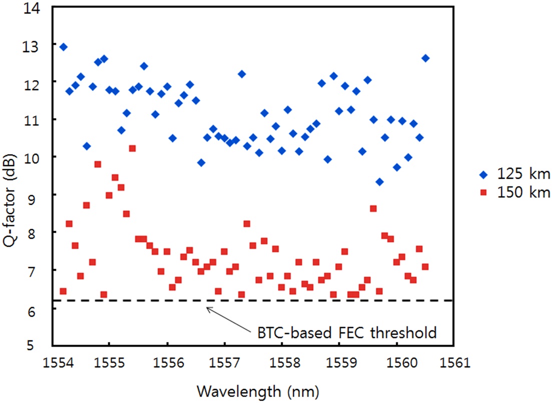
    Figure 6 shows the Q-factor values after 125 and 150 km without any dispersion compensations. All of the Q-factor values are above the FEC threshold. For the 125-km transmission, the minimum BER is 1.1 × 10⁻³. For the 150-km transmission, the minimum BER is 1.9 × 10⁻². Thus, if we neglect the system margin, 150 km is the maximum transmission distance of our system. Without the VSB filtering, the maximum transmission distance of the same system is measured to be less than 100 km.

    When we change the bit rate to 10.7 Gb/s with all other conditions the same, we have BER ~ 3 × 10⁻³ typically after the 100 km. This is worse than the FEC threshold, BER = 1 × 10⁻⁴. For the 12.4-Gb/s bit rate, but with the reduced channel spacing of 10 GHz, we have BER ~ 4.8 × 10⁻⁴ and 1.8 × 10⁻² for the back to back and the 125-km transmission, respectively. Thus, with the VSB filtering, we have achieved the spectral efficiency of 1 bit/s/Hz up to 125 km.

    Note that the FP filter’s FSR is dependent only on the mirror spacing. Over the whole C-band, the dielectric mirror’s reflectivity changes within a few percent. Thus, in stable conditions, our FP filters may cover hundreds of 12.5-GHz spaced optical channels.

    To demonstrate the usefulness of our Fabry-Perot filter pair, we have chosen 10 Gb/s bit rate rather than 40 Gb/s or higher bit rates. To achieve high spectral efficiencies, 12.5 and 10 GHz channel spacing values are used. In this narrow channel spacing, the FEC techniques are indispensible because of high cross talks [16]. Our transmission system, in its present form, may be used for metro networks [17] and WDM passive optical networks [18-20] where many low bit rate channels are preferred. The transmission distance can be increased to a long-haul scale if we use dispersion-managed transmission techniques [21].

    In our experiment, the FP filters are placed on a vibrationfree optical table. With our thermally-matched mechanical mounts in Fig. 2(b), the FP filters operate stably during the experiment and their transmission peak wavelengths change by 4 pm/deg. However, to obtain long-term stabilities, active controlling apparatuses will be needed. The stability of FP filters can be enhanced greatly if they are integrated within a single chip using, for example, micro-electromechanical systems technologies [22-24].

    IV. CONCLUSION

    We have proposed to use a pair of FP filters for the VSB filtering of WDM channels. The transmittance curve of each FP filter is made to have sharp skirts using an offset between input and output coupling fibers. Having an excellent periodic property, the FP filters are advantageous over conventional VSB filters covering a large number of optical channels simultaneously. We have demonstrated a simultaneous VSB filtering of 12.5-GHz spaced 64 × 12.4 Gb/s channels using a pair of FP filters achieving a record high 64 simultaneously VSB filtered channels. The VSBfiltered channels have been transmitted successfully over an SMF up to 150 km.

참고문헌
  • 1. Yonenaga K., Takachio N. (1993) “A fiber chromatic dispersion compensation technique with an optical SSB transmission in optical homodyne detection systems” [IEEE Photon. Technol. Lett.] Vol.5 P.949-951 google cross ref
  • 2. Wu L., Li M., Zhang F., Chen Z. Y., Chen L.-K., Xu A. S. (2010) “Fibre nonlinearity mitigation of OOK signals with MLSE utilising MZ filter for diverse VSB filtering” [Electron. Lett.] Vol.46 P.780-781 google cross ref
  • 3. Kim H., Gnauck A. H. (2001) “10 Gbit/s 177 km transmission over conventional singlemode fibre using a vestigial sideband modulation format” [Electron. Lett.] Vol.37 P.1533-1534 google cross ref
  • 4. Turitsyna E. G., Webb S., Mezentsev V. K., Turitsyn S. K. (2006) “Novel design of FBG-based composite double notch VSB filter for DWDM systems” [J. Lightwave Technol.] Vol.24 P.3547-3552 google cross ref
  • 5. Jansen S. L., Derksen R. H., Schubert C., Zhou X., Birk M., Weiske C.-J., Bohn M., van den Borne D., Krummrich P. M., Moller M., Horst F., Offrein B. J., de Waardt H., Khoe G. D., Kirstadter A. 2007 “107-Gb/s full- ETDM transmission over field installed fiber using vestigial sideband modulation” [in Proc. OFC] P.OWE3-1-OWE3-3 google
  • 6. Idler W., Bigo S., Frignac Y., Franz B., Veith G. 2001 “Vestigial side band demultiplexing for ultra-high capacity (0.64 bit/s/Hz) transmission of 128 × 40 Gb/s channels” [in Proc. OFC] P.MM3-1-MM3-4 google
  • 7. Jang H. D., Kim K. S., Lee J. H., Jeong J. C. (2009) “Transmission performance of 40 Gb/s PM doubinary signals due to fiber nonlinearities in DWDM systems using VSB filtering techniques” [J. Opt. Soc. Korea] Vol.13 P.354-360 google cross ref
  • 8. Yu C. X., Neilson D. T. (2002) “Diffraction-grating-based (de) multiplexer using image plane transformations” [IEEE J. Select. Topics Quantum Electron.] Vol.8 P.1194-1201 google cross ref
  • 9. Qian D., Yu J., Hu J., Zong L., Xu L., Wang T. (2008) “10 Gbit/s WDM-SSB-OFDM transmission over 1000 km SSMF using conventional DFB lasers and direct-detection” [Electron. Lett.] Vol.44 P.223-225 google cross ref
  • 10. Tang Y., Shieh W. (2009) “Coherent optical OFDM transmission up to 1 Tb/s per channel” [J. Lightwave Technol.] Vol.27 P.3511-3517 google cross ref
  • 11. Liu X., Wood T. H., Tkach R. W., Chandrasekhar S. (2012) “Demonstration of record sensitivities in optically preamplified receivers by combining PDM-QPSK and M-ary pulse-position modulation” [J. Lightwave Technol.] Vol.30 P.406-413 google cross ref
  • 12. Song D. Y., Lee J. S. (2000) “Angle-tuned Fabry-Perot etalon filter having Gaussian transmittance curves” [IEEE Photon. Technol. Lett.] Vol.12 P.1186-1188 google cross ref
  • 13. Mizuochi T., Miyata Y., Kobayashi T., Ouchi K., Kuno K., Kubo K., Shimizu K., Tagami H., Yoshida H., Fujita H., Akita M., Motoshima K. (2004) “Forward error correction based on block turbo code with 3-bit soft decision for 10-Gb/s optical communication systems” [IEEE J. Select. Topics Quantum Electron.] Vol.10 P.376-386 google cross ref
  • 14. “Appendix A: forward error correction using 16-Byte interleaved RS(255 239) codecs, 03/2003” google
  • 15. DeLange O. E. (1968) “Optical heterodyne detection” [IEEE Spectrum] Vol.5 P.77-85 google
  • 16. Hurh Y. S., Hwang G. S., Jeon J. Y., Lee K. G., Shin K. W., Lee S. S., Yi K. Y., Lee J. S. (2005) “1-Tb/s (100 12.4 Gb/s) transmission of 12.5-GHz-spaced ultradense WDM channels over a standard single-mode fiber of 1200 km” [IEEE Photon. Technol. Lett.] Vol.17 P.696-698 google cross ref
  • 17. Tzanakaki A., Zacharopoulos I., Parcharidou D., Tomkos I. (2004) “Performance study of modulation formats for 10-Gb/s WDM metropolitan area networks” [IEEE Photon. Technol. Lett.] Vol.16 P.1769-1771 google cross ref
  • 18. Kani J. (2010) “Enabling technologies for future scalable and flexible WDM-PON and WDM/TDM-PON systems” [IEEE J. Select. Topics Quantum Electron.] Vol.16 P.1290-1297 google cross ref
  • 19. Kang B. W., Kim C. H. (2011) “An amplified WDM-PON using broadband light source seeded optical sources and a novel bidirectional reach extender” [J. Opt. Soc. Korea] Vol.15 P.222-226 google cross ref
  • 20. Lee H. J. (2011) “External optical modulator using a low-cost Fabry-Perot LD for multicasting in a WDM-PON” [J. Opt. Soc. Korea] Vol.15 P.227-231 google cross ref
  • 21. Suzuki M., Edagawa N. (2003) “Dispersion-managed highcapacity ultra-long-haul transmission” [J. Lightwave Technol.] Vol.21 P.916-929 google cross ref
  • 22. Milne J. S., Keating A. J., Dell J. M., Faraone L. 2008 “MEMS -based tunable Fabry-Perot filters on silicon substrates” [in Proc. IEEE Conf. on Optoelectronic and Microelectronic Materials and Devices] P.174-180 google
  • 23. Hays D., Zribi A., Chandrasekaran S., Goravar S., Maity S., Douglas L. R., Hsu K., Banerjee A. (2010) “A hybrid MEMS ?fiber optic tunable Fabry-Perot filter” [J. Microelectromech. Syst.] Vol.19 P.419-429 google cross ref
  • 24. Chennakesava R. M. K., Priya M. S., Meenakshi M., Kalaiarasi A. R. 2012 “Mems-based wide range tunable Fabry- Perot filter” [in Proc. IEEE International Conference on Advances in Engineering, Science and Management (ICAESM 2012)] P.266-268 google
OAK XML 통계
이미지 / 테이블
  • [ FIG. 1. ]  Experimental setup. LD: laser diode, AWG: arrayed-waveguide grating, PM-C: polarization maintaining coupler, MZM: LiNbO3 Mach-Zehnder modulator, PC: polarization controller, FP: Fabry-Perot, PBC: polarization beam combiner, EDFA: erbium-doped fiber amplifier, SMF: single-mode fiber, BPF: band-pass filter, Rx: optical receiver, BERT: bit-error-rate tester.
    Experimental setup. LD: laser diode, AWG: arrayed-waveguide grating, PM-C: polarization maintaining coupler, MZM: LiNbO3 Mach-Zehnder modulator, PC: polarization controller, FP: Fabry-Perot, PBC: polarization beam combiner, EDFA: erbium-doped fiber amplifier, SMF: single-mode fiber, BPF: band-pass filter, Rx: optical receiver, BERT: bit-error-rate tester.
  • [ FIG. 2. ]  Fabry-Perot filter with an offset. OSA: optical spectrum analyzer. (a) Schematic of the Fabry-Perot filter with an offset. (b) Photograph of the Fabry-Perot filter with an offset.
    Fabry-Perot filter with an offset. OSA: optical spectrum analyzer. (a) Schematic of the Fabry-Perot filter with an offset. (b) Photograph of the Fabry-Perot filter with an offset.
  • [ FIG. 3. ]  Transmittance curves of the FP filter used for the odd channels at θ = 0.75° with the offset of (a) 0 μm, (b) +100 μm, and (c) +200 μm.
    Transmittance curves of the FP filter used for the odd channels at θ = 0.75° with the offset of (a) 0 μm, (b) +100 μm, and (c) +200 μm.
  • [ FIG. 4. ]  Spectra of a single channel measured by a heterodyne detection technique (a) before and (b) after the FP filter.
    Spectra of a single channel measured by a heterodyne detection technique (a) before and (b) after the FP filter.
  • [ FIG. 5. ]  64 channel spectrum after the PBC. The optical resolution is 0.05 nm.
    64 channel spectrum after the PBC. The optical resolution is 0.05 nm.
  • [ FIG. 6. ]  Q-factor values for the 12.4 Gb/s channels after the SMF 125 km and 150 km.
    Q-factor values for the 12.4 Gb/s channels after the SMF 125 km and 150 km.
(우)06579 서울시 서초구 반포대로 201(반포동)
Tel. 02-537-6389 | Fax. 02-590-0571 | 문의 : oak2014@korea.kr
Copyright(c) National Library of Korea. All rights reserved.