Laser coatings played a vital role in a nanosecond pulse laser system, especially in huge laser facilities such as NIF (National Ignition Facility) in America or LMJ (Laser Megajoule) in France [1-4]. To increase the power transfer efficiency, these transmittance optical elements, such as antireflection (AR) coatings, must resist as high laser irradiation as high reflection coatings. It is a fact that laser-induced damage of AR coatings was a limiting factor on reliable operation of such high-power solid-state lasers. Many studies on how to improve transmittance element damage threshold have been carried out over the past decades years [5-8]. Among these studies, understanding the origin and mechanisms of laser-induced damage was important for the improvement of the laser radiation resistivity of the AR coatings. Laser induced damage on transmissive optics was often associated with absorbing contaminants introduced by the polishing process. For the conventionally polished fused silica substrate, an around 100 nm depth redeposition polishing layer was formed on the top of surface [9]. Polishing compounds densely embedded in the redeposition polishing layer were the dominant factor that limited the laser induced damage threshold (LIDT) of transmissive elements in nanosecond laser systems. Thus, how to remove the absorbing contaminants effectively was the key point to enhance the AR coatings damage resistance.
There were several ways to improve the substrate quality and eliminate the polishing contaminants, such as chemical etching, superpolishing, magnetorheological polishing, ion beam etching, laser conditioning, and so on [10,11]. Among these techniques, chemical etching was widely used because of its effectiveness and efficiency of removing subsurface defects, but it would deteriorate the scratch and fractures at the same time, especially when the etching depth was too large. Superpolishing was adopted mainly for improving the surface quality. The ion beam etching technique was effective at removing the polishing compound and it had been successfully used to improve the laser damage resistance of the substrate at 355 nm [12]. This paper tried to present the connection between improvements of laser damage resistance of AR coatings and substrate pretreating before coatings deposition. For this purpose, several substrate etching techniques and a superpolishing process were used to eliminate the residual polishing compound from the conventional polished surface. The laser induced damage threshold of these samples with several surface removal processes was tested to evaluate the treatment effect.
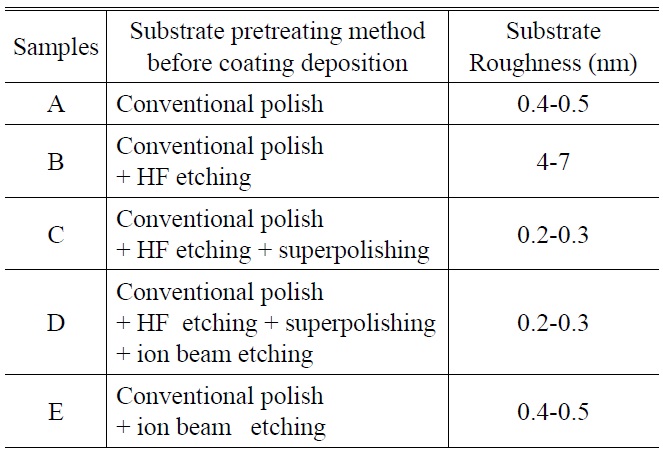
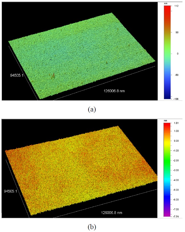
The investigations were performed on conventionally CeO2 polished UV-grade 30 mm diameter fused silica samples (purchased from Z & Z Optoelectronic Tech. Co., Ltd, China). Surface roughness of these samples was less than 0.5 nm. Table 1 summarized the various substrate treatments. Sample A was an AR coating deposited on conventional polish fused silica substrate. Substrate of sample B was chemically etched to a depth of 1000 nm in 40% buffered hydrofluoric acid (HF) solution. As discussed above, the HF etching could remove subsurface defects effectively and efficiently, but at the same time, the surface roughness degraded considerably from 0.4 nm to about 5 nm. Fig. 1(a) presented the surface topology of HF etched silica substrate.
In order to repair the surface roughness of the substrate after HF etching, to the substrate of sample C added a super-precise polishing process compared with sample B. A surface roughness of 0.2-0.3 nm was obtained after superpolishing. Comparing with sample C, the substrate of sample D had been etched to a depth of 100 nm through an ion beam etching technique to remove the polishing re-deposition layer without degrading surface quality, their surface roughness was also 0.2-0.3 nm. To sample E, the substrate was treated only by the ion beam etching process, the etched depth was about 100 nm. Meanwhile, the surface

Various treatments applied to the fused silica substrate and surface roughness of substrate
roughness kept the same value as that of conventional polished surface, which was shown in Fig. 1(b).
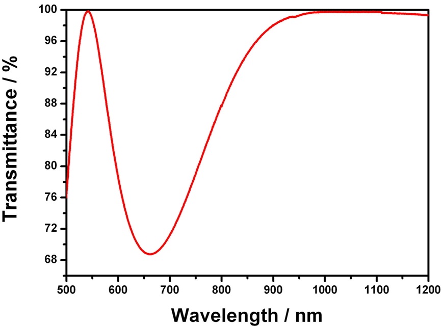
After substrate treating, all the silica substrates including these as-supplied ones had been deposited in one batch using an electric beam evaporation method. The metal hafnium and particle SiO2 had been used as high-index and low-index materials, and a 5 layer design had been adopt with the SiO2 layer to be the buffering layer. Fig. 2 showed the transmittance spectra of these samples, there
was no measurable difference in transmittance after coating. All of them reached 99.8% at 1064 nm.
LIDT testing for 1064 nm was performed on each sample to investigate the effects of substrate pretreating technology. To make the LIDT data more reliable, three specimens of each kind of sample were tested. A “1-on-1” damage testing according to ISO standard 11254-1, using Q-switched Nd:YAG pulsed laser with pulse length 10ns was used for the LIDT measurement. The laser beam was focused with a 1500 mm focal length lens. The focused laser beam had a smooth Gaussian shape with a spot diameter at 1/e2 peak intensity of 1 mm. A Nomarski microscope at 200X was used to detected damage. The LIDT was defined as the maximum incident pulse energy density at which the possibility of damage is 0%.
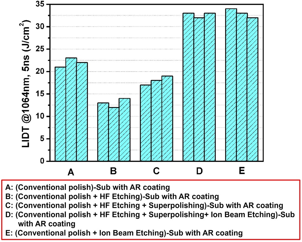
Figure 3 presented the laser damage testing result. We can see that not all substrate treatments increased the LIDT of AR coatings. The sample A that used the conventional polish substrate without any treatment had damage threshold at around 22 J/cm2. Compared with the as-supplied substrate (sample A), the LIDT of sample B decreased sharply from 22 J/cm2 to 13 J/cm2. This was thought to be mainly due to the relatively high microroughness of substrate after HF etching and appeared to be more detrimental to the coated substrate than the bare one [5]. Bloembergen [13] had determined that increasing in surface roughness locally enhanced the electric field strength and scattering loss. Sample C had a higher LIDT than sample B, it reached 17 J/cm2. It can be seen that the superpolishing technique can increase the LIDT to some extent, which was mainly due to the repair effect to the surface roughness. As we know, the irregular structure of a rough surface contains more
and bigger-size absorption centers than that of a smooth one [14]. Although the LIDT of sample C had been enhanced 1.3 times compared with sample B, it was still lower than sample A. The reason might be due to the inappropriate HF etched depth, it caused more unstable scratch and fractures to expose (This also can be seen from fig. 1), which provided sites for light-absorbing contaminations to reside.
The exciting thing was that the damage thresholds of both samples D and E were higher than those of samples A, B and C. The LIDT of 32 J/cm2 was obtained from the all ion-beam etched surfaces, and the LIDT enhancement reached to 1.45 times compared with the sample used assupplied substrate. The explanation for the improvement was that mechanical polishing processes produced a layer of subsurface fractures that can trap absorbing contaminants such as the polishing compound during polishing. The ion-beam etching process successfully removed the layer of fractures and associated contaminants, while the appropriate energy ions did not penetrate or disrupt the structure near the surface. At the same time, these results agreed well with the depth profile of embedding polishing compound as suggested by Kozlowski [7].
Also notable was that the LIDT of sample D and E was the same. No matter how many different routes for substrate preparation had been used, so long as the ion beam etching had been carried out in the last step, the LIDT of AR coatings can be enhanced. Taking all samples into consideration, we can conclude that only ion beam etching can effectively remove the polishing compound and did not induce extra absorbers during the disposal process, to improve the laser damage resistance of AR coatings at 1064 nm. The difference between the conventional polishing and superpolishing techniques was only the depth and quantity of the residual polishing compounds. Both the conventional polishing and super-polishing technique were mechanical polishing method, they must use polishing compounds and will inevitably induce extra scratches and pits, then the residual polishing compounds can undesirably be embedded.
In conclusion, the effect of HF chemical etching, superpolishing and ion-beam etching on damage resistance in AR coating has been studied. Mechanically polished substrate surfaces were contaminated with polishing contaminants in the polishing slurry. Residual polishing compound was embedded in the redeposition polishing layer of the substrate, and was difficult to remove by traditional cleaning techniques. By means of comparing of different substrate pretreatment techniques including superpolishing, HF etching and ion beam etching, it was found that only ion beam etching was effective in improving the laser damage resistance of AR coatings at 1064 nm, which was mainly due to the efficient ability to remove the residual polishing compounds in the substrate. This technique was very useful in fabricating high laser-damage resistant optical surfaces for high-power lasers.